|
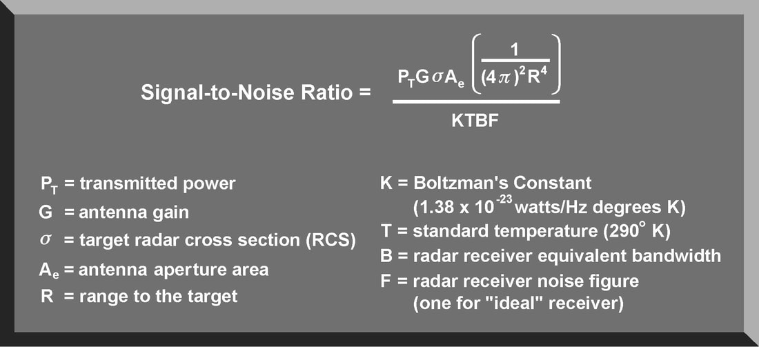
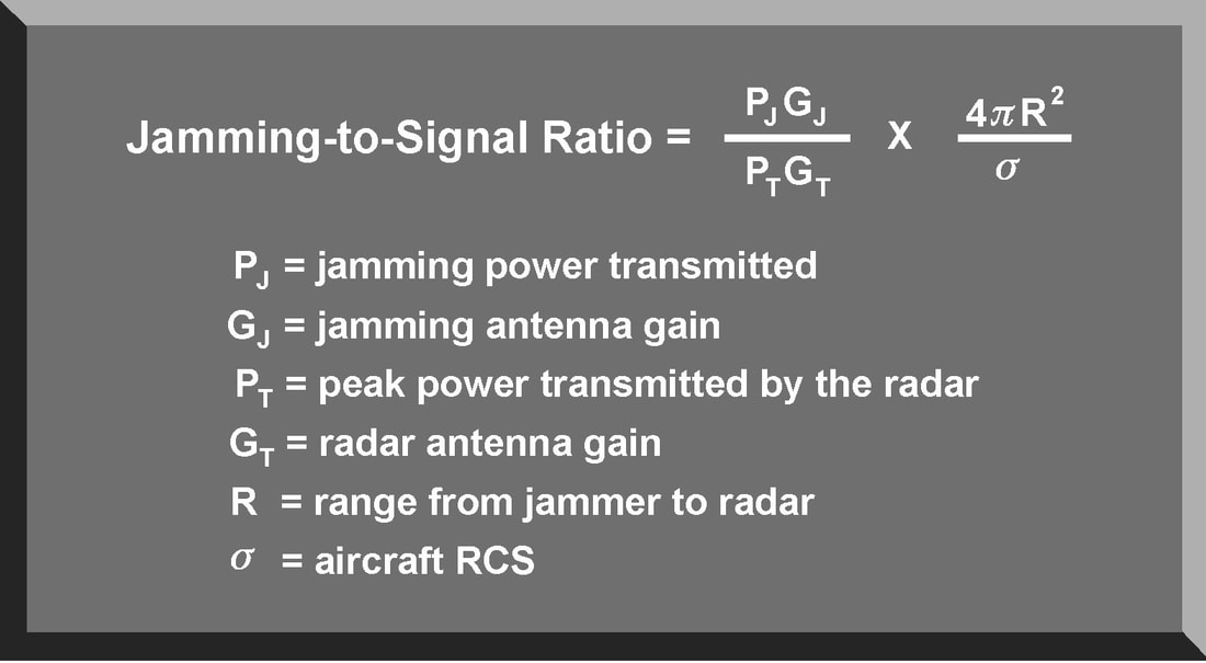
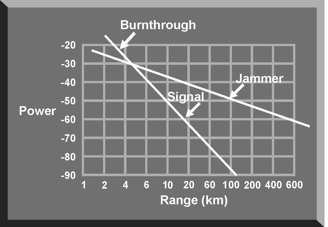
There are some fundamental principles that apply to all types of jamming and to all jamming employment options. These principles are based on the characteristics of the jamming system and the characteristics of the victim radar. They include frequency matching, continuous interference, signal-to-noise ratio, jamming-to-signal ratio, and burnthrough range. Based on the data provided by ES systems and intelligence evaluations, radar jamming systems must transmit signals at the frequency of the victim radar This applies to both noise and deception jamming. If a jamming signal does not match the transmitter frequency, the jamming signal is not received and displayed on the scope. When a jamming signal matches the transmitter frequency, the jamming signal is received and masks the target display . For maximum effectiveness, a jamming transmitter should produce continuous interference. In much the same way intermittent static on a radio receiver does not completely block out a signal, intermittent jamming on a radar scope may not completely mask the target. An experienced radar operator or advanced automatic tracker can “read through” intermittent jamming and derive sufficient target information to negate jamming effectiveness. While true for noise jamming techniques, continuous interference also applies to deception techniques, especially when target reacquisition is considered. Signal To Noise Ratio The signal-to-noise (S/N) ratio is a measure of the ability of the victim radar to detect targets. It is also an indication of the vulnerability of the radar to certain jamming techniques, especially noise jamming. The signal power density of the target return is so weak that it requires very strong amplification before processing and display. Besides the signal power from the target, some level of thermal noise is also generated and amplified along with the target signal. The radar receiver amplifies both target signal and thermal noise. The output of the radar receiver will contain the target signal and the noise amplified across the bandwidth of the receiver. Separating the desired target signal from the undesired noise signal is one of the major problems confronting radar designers. Target RCS fluctuates based on the changing angle of the antenna beam and corresponding changes in the reflected signal. Effective antenna aperture is also a statistical phenomenon based on the fluctuations in target RCS. The thermal noise generated by a receiver is also a fluctuating factor and must be treated statistically. This means that the S/N ratio is a statistical factor associated with a probability of target detection and a probability of a false alarm. A false alarm occurs when the radar operator or automatic tracking circuit designates a fluctuation in noise level as a target. The higher the S/N ratio, the higher the probability of target detection with a corresponding reduction in the probability of a false alarm. Any action that increases the power in the target signal (for example, increasing transmitted power, increasing antenna gain/aperture area, or decreasing target range) will improve the S/N ratio and improve the probability of target detection. It would also appear that decreasing the bandwidth of the radar receiver will increase the S/N ratio and enhance the probability of target detection. However, if the effective bandwidth of the receiver is reduced, this may eliminate a significant portion of the radar signal spectrum and decrease the probability of target detection. The S/N ratio is also an indication of the range at which a target will be detected. The weak target signal at an extended range is just above the receiver noise level. The target at closer range is easily detected above the noise level. A radar operator or automatic target detector could mistake the very weak target return as a fluctuation in the receiver noise level. This could result in a missed detection. The lack of discrimination between noise and target returns because of a poor S/N ratio can also result in designating fluctuations in the noise level as actual target signals, known as false alarms. To preclude, or minimize false alarms, the radar receiver may be equipped with electronic circuits to establish a false alarm threshold. If the signal strength of a radar return is below this threshold level, it will not be detected or displayed. This false alarm threshold also influences the probability of target detection. With the threshold set too high, many detected targets will not be displayed. Additionally, if the false alarm threshold is raised automatically in relation to the amplitude of the receiver noise, the radar receiver is more vulnerable to noise jamming. For any target return to be detected by the radar, the S/N ratio must be greater than one. If the S/N ratio is less than one, the target will not be detected above the receiver noise level. The purpose of noise jamming is to raise the level of noise in the radar receiver to reduce the S/N ratio to less than one. This masks the presence of the true target return. If a false alarm threshold is used, noise jamming raises this threshold to further complicate target detection Jamming-to-signal (J/S) ratio The jamming-to-signal (J/S) ratio is a fundamental measure of jamming effectiveness. The J/S ratio compares the power in the jamming signal with the power in the radar return. Equation 9-4 is an expression of the J/S ratio. It is important to note that the J/S ratio should be measured at the output of the radar receiver. This will allow consideration of the receiver signal processing gain applied to the jamming signal. The most critical factor in both the S/N and the J/S ratios is range. The S/N ratio is calculated based on R to the fourth power. This equates to a signal traveling from the radar to the target, and back to the radar receiver. The J/S ratio is calculated using R to the second power. This factor reflects the “one way” transmission of the jamming pulse from the jammer to the victim radar's receiver. For a jamming signal to be effective, the J/S ratio must be greater than one. In general, threat radars, especially ground-based radars, transmit much more power than does an airborne jamming system. However, this power must travel twice as far as the airborne jamming signal. At long ranges, a low power jamming system can generate a J/S ratio much greater than one. As the jamming system approaches the target, the distance the radar pulse travels decreases with a corresponding increase of power in the radar return. This reduces the J/S ratio to a value less than one and the radar “sees” the target. This is called the burnthrough range. Burnthrough Burnthrough occurs when the power in the reflected target signal exceeds the power in the jamming signal. Even when an optimum and continuous jamming technique is transmitting on the exact frequency of the victim radar, the jamming starts to lose effectiveness as it nears the radar. For a particular radar jamming technique, burnthrough range depends on the detection capability of the victim radar, expressed as the S/N ratio, and the capability of the aircraft's jamming system, expressed as the J/S ratio. The idea of burnthrough range explains why a jamming technique, especially noise jamming, loses its effectiveness as the aircraft approaches the radar. When plotting the jamming and signal power versus range , these two values intersect at the point where the J/S ratio is one. At closer ranges, the jamming pulse is no longer masking the aircraft, and the aircraft can be detected. Burnthrough range is the point where the radar can see through the jamming. SUMMARY
The purpose of radar jamming is to confuse or deny critical data to the radar systems that play a vital role in supporting the mission of an integrated air defense system. Two types of radar jamming, noise and deception, can be employed in a support-jamming role, or in a self-protection role for individual aircraft. The effectiveness of a jamming technique depends on the ability of the jamming system to generate a jamming signal that replicates the parameters of the victim radar, especially its frequency. The signal-to-noise ratio of the victim radar determines the vulnerability of the radar receiver to jamming while the jamming-to-signaI ratio is an indication of the ability of the jamming system to effectively jam the victim radar. These basic radar jamming concepts are fundamental to understanding the impact of specific jamming techniques on radar systems. Once a target has been designated, acquired, and tracked by a radar system, the final stage in target engagement is to guide a missile or projectile to destroy the target. There are three basic requirements for successful missile guidance:
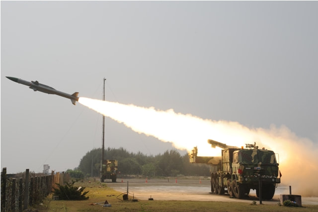
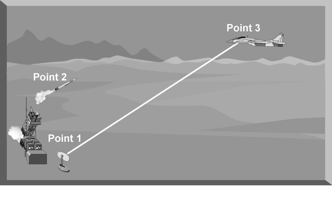
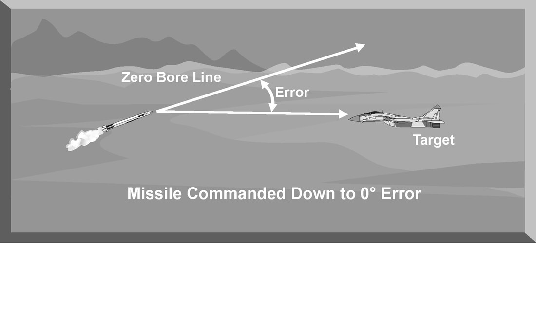
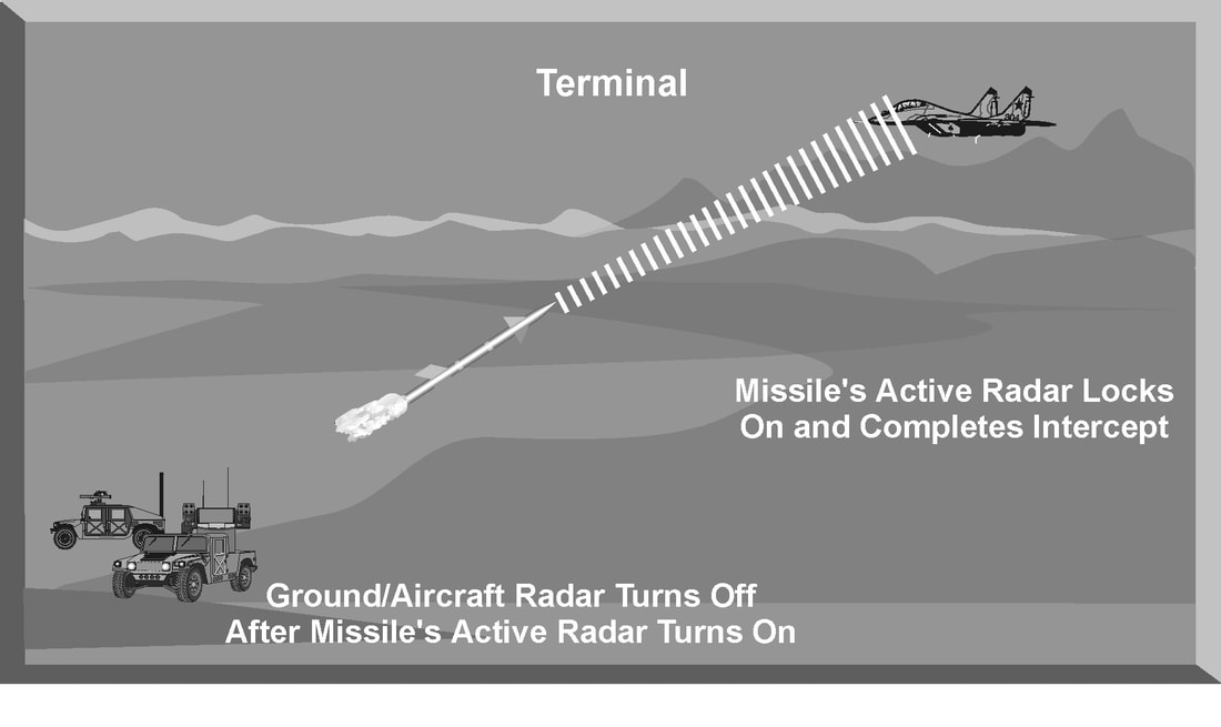
There are three distinct phases in any missile intercept: boost, mid-course, and terminal. Nearly all missiles are unguided during the initial boost phase. During the boost phase, the missile electrical and hydraulic systems are activated and are coming up to operating parameters. The missile is gathering speed and normally will be in an unguided mode of flight. During the mid-course phase, the missile is actively being guided to the target using some type of guidance signal. Guidance signals deflect the control vanes of the missile to change its direction. These vanes change the roll, pitch, and yaw, in some combination, to control the missile flight path. Normally a gas grain generator powers a small hydraulic pump that deflects the control vanes in response to guidance signals. Each missile carries a limited supply of hydraulic fluid for maneuvering. The fluid is expended through vents with every control surface activation. The limited quantity of hydraulic fluid can be a significant factor during a long-range missile intercept. The final phase of an intercept is the terminal phase. During this phase, the missile attempts to pass close enough to the target to detonate the fuse while the target is within the lethal radius of the warhead. Modern missiles employ both a contact fuse and some type of proximity fuse. Proximity fuses range from command detonation for command-guided missiles, fractional Doppler gates for semi-active guided missiles, to active laser fuses for IR-guided missiles. COMMAND GUIDANCE Command guidance uses a fire control computer to constantly send course correction commands to the missile throughout its flight. These commands are a series of electrical missile guidance pulses called doublets or triplets. These pulses provide steering commands to the missile by varying the spacing between each guidance pulse. Each pulse, or pulse combination, relays some roll, pitch, and yaw command to the missile. These inputs are constantly corrected for the spatial relationship between the missile and the target's present position and rate of motion. Guidance commands are passed to the missile by specialized antennas on the TTR and an antenna installed on the missile, called a missile beacon. The beacon is a special radio receiver and transmitter that is attached to the rear of the missile. It acts like a transponder in that the TTR tracks and receives guidance commands. The guidance frequency may be widely separated from the target tracking radar frequency to minimize interference. This beacon is usually masked until missile booster separation. These results in the missile being launched unguided for the first 2-3 seconds. This type of delay is one of the reasons that all command-guided missile systems have a minimum launch range. Command-guided missiles will generally fly a rectified (full or half) or threepoint pursuit geometry during the mid-course portion of the intercept. However, a command-guided missile may transition to pure pursuit geometry during the terminal phase of the intercept. Rectified geometry involves the prediction of where the target and the missile will be at some point in the future. The target's direction and rate of movement is tracked and predicted. The missile is then launched, pulls lead on the target, and is guided to the point in the sky where the intercept is predicted to take place. This profile requires the constant update of both the target and missile positions. Three-point pursuit geometry is often used when there is incomplete range tracking data on the target. In this case, it will be impossible to predict exactly where the target will be at some point in the future. In this profile, the target tracking radar constantly tracks the target. The missile location will be updated by the missile beacon. The fire control computer will direct the missile to fly directly down the tracking radar beam toward the target. In this geometry, the missile may start out on a direct intercept course and, depending on the target's direction and rate of movement, transition to a pure pursuit intercept. The three points in three-point missile geometry are depicted in Figure. Point one is the target tracking radar, point two is the missile itself, and point three is the target. By keeping all three points always in a line, the missile will intercept the target at some point, although the range of the target is unknown. Advantages Command guidance techniques have many advantages. First, command guided missiles can adjust their flight geometry throughout an intercept profile. Second, the missiles are uncomplicated since they do not carry onboard computers or target tracking equipment. The fire control computer associated with the TTR accomplishes all intercept calculations. Third, the primary intercept profile, a full- or half-rectified intercept, is the fastest and most fuel-efficient intercept. Fourth, command guidance is difficult to jam since the missile beacon antenna is at the rear of the missile and can be relatively high-powered. And finally, an intercept is possible even without accurate range information by using the three point intercept profile. Disadvantages Command guidance has several disadvantages. First, the use of a missile beacon delays the capture of the missile by the tracking radar. This can cause a large dead zone which equates to a larger minimum engagement range. Second, the accuracy of the intercept geometry is only as good as the tracking information provided by the target tracking radar. Jamming, interference, or loss of signal will adversely affect the intercept accuracy. In addition, normal radar characteristics could produce sufficient errors to cause the missile to miss the target, especially at longer ranges. Third, with insufficient range information, the three-point intercept profile is very slow and could result in the missile running out of energy before it gets to the target. Fourth, command guidance is reactive. The fire control computer constantly updates the intercept geometry based on target maneuvering. This results in missile maneuvering lagging target maneuvers. SEMI-ACTIVE GUIDANCE Semi-active guidance is significantly different from command guidance, but only after launch. The first requirement is still for the target tracking radar to maintain a solid target track, with the tracking data being supplied to the fire control computer. The fire control computer then directs a target illumination antenna to point at the target and illuminates it with CW energy. The missile then passively homes on the reflected CW energy. The missile used by a threat system that uses CW homing is vastly different from the missile being guided by a command guidance signal. The missile that homes on CW energy must be equipped with a seeker section composed of an antenna and an internal receiver. The seeker section processes and computes the necessary course corrections as it flies toward the target. It can do this by knowing the zero boresight line of the antenna within the missile. As the reflected CW energy is received by the seeker, there is normally some deviation from the zero reference position. The onboard computer then directs the control surfaces to change the flight path to reduce the reference errors in the antenna to zero, if possible. When the error between the antenna position and the boresight position is zero, the missile is pointed directly at the target. Missile systems that use semi-active guidance normally use velocity as the primary target discriminator during the intercept. The missile seeker locks onto a reference Doppler signal provided by the fire control computer before launch. This Doppler signal establishes a tracking gate around the velocity of the target. After the missile is launched, it initially compares the reference Doppler to the target Doppler signal. The mid-course phase for a semi-active missile is also different from that of a command-guided missile. A semi-active guided missile follows the reflected CW energy during the mid-course phase of the intercept and normally attempts to fly a lead pursuit profile to the target. If the target maneuvers, however, the missile may transition to a pure pursuit flight path. Unlike a command-guided missile, a semi-active guided missile does not use a missile beacon. The fire control computer does not need to know where the missile is to compute course corrections since all that is necessary is to illuminate the target with the CW illuminator. This also means that the missile can begin to track and guide when it is launched and locked on to the reference Doppler gate. Semi-active guidance is the primary mode of guidance for many surface-to-air missiles, and radar-guided air-to-air missiles. As the missile enters the terminal phase of the intercept, there is no change in the guidance mode used by a CW homing missile. The missile may complete the terminal phase of the intercept geometry by going to a pure pursuit flight path, if necessary. The missile continues to home in on the reflected CW signal until it passes close enough for the fuse to function. Advantages Semi-active missile guidance has many advantages. First, a semi-active guided missile is resistant to electronic jamming that may be used to deny range information. Second, a semi-active missile can be guided almost immediately after launch. This gives it a very small minimum range since it can maneuver almost as soon as it clears the launch rail. Third, it computes its own course corrections as necessary. This allows for a much quicker reaction to target maneuvers compared to a command-guided missile. Fourth, during a long-range intercept, a CW missile can be more accurate than a command-guided missile. This is accomplished by taking the inherent long-range radar tracking errors out of the equation. The target tracking radar only has to keep the target illuminated so that it can point the CW antenna at the target. Disadvantages Although semi-active missile guidance is generally considered an excellent guidance technique, it does have some disadvantages. First, a semi-active guided missile normally requires reference Doppler values to be entered into the missile computer before launch. Without this reference, a semi-active missile cannot be launched. Second, a semi-active homing missile must maintain a lock onto the target Doppler. The use of chaff and beam maneuvers, which result in a near zero target Doppler, may cause a missile or radar to break lock. Third, if a break-lock occurs, a CW homing missile normally cannot regain target track and complete the intercept. ACTIVE GUIDANCE This specialized guidance mode is only active during the terminal phase of flight. The mid-course phase usually employs semi-active or command guidance. The range at which the missile goes “active” is dependent on the intercept geometry. High-aspect angle intercepts allow the activation of active guidance sooner than beam or tail-aspect intercepts. Missiles that employ active guidance carry a complete miniature radar system and fire control computer within the missile. As the missile nears the target, its internal radar system turns on and locks onto the target. The internal fire control computer directs control inputs to complete the intercept Advantages Active-guided missiles have many advantages. First, active-guided missiles are very accurate at long ranges. This is because they do not rely on the target tracking radar once their internal radar takes over the intercept. Second, an active missile is extremely difficult to jam. It uses a narrow beam and its relative power is constantly increasing as it nears the target. Third, an active-guided missile is a fire-and-forget weapon. Command or semi-active missile guidance requires the target tracking radar to maintain lock-on until the intercept is completed. In an air-to-air engagement, this means the interceptor is predictable until the missile hits the target, and vulnerable to an enemy missile attack. An interceptor with an active missile, however, may launch the missile and, once it goes “active,” can then turn around or maneuver defensively. Disadvantages Active-guided missiles have a few disadvantages as well. First, the active homing missile is a complex missile integrating both command and active guidance modes. Second, the missile may still be susceptible to electronic jamming during the mid-course phase of flight. Remember, during the mid-course phase, the missile relies on command or semi-active guidance. Jamming the target tracking radar may affect the missile's ability to “see” the target near the terminal phase. SEEKER-AIDED GROUND GUIDANCE/TRACK-VIA-MISSILE GUIDANCE
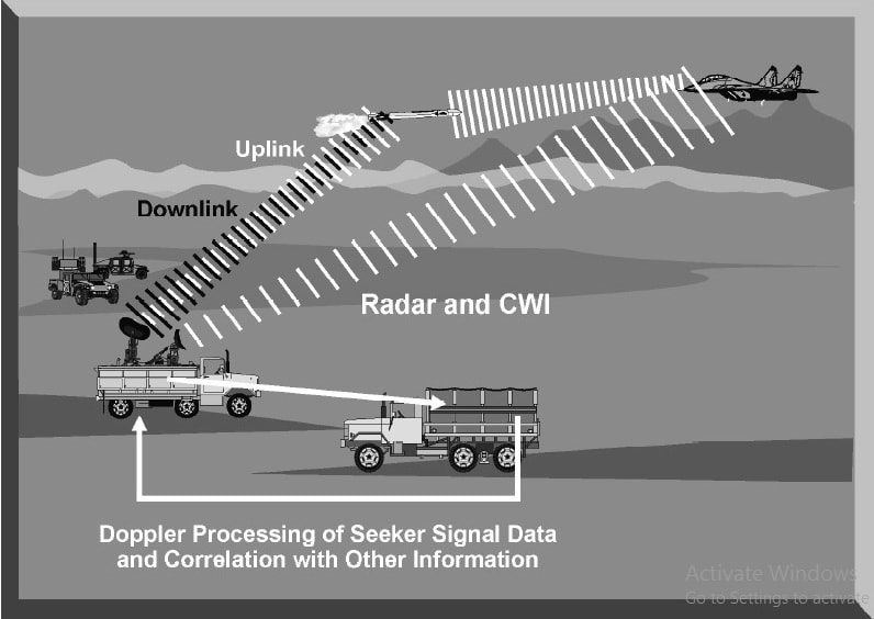
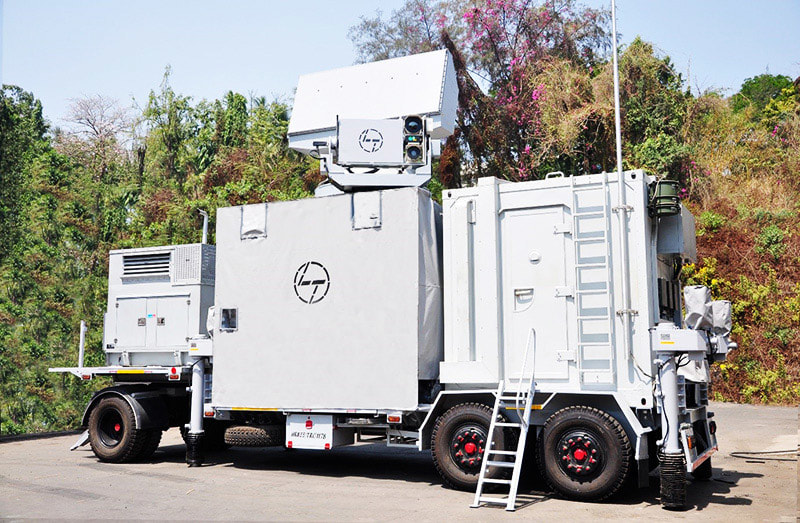
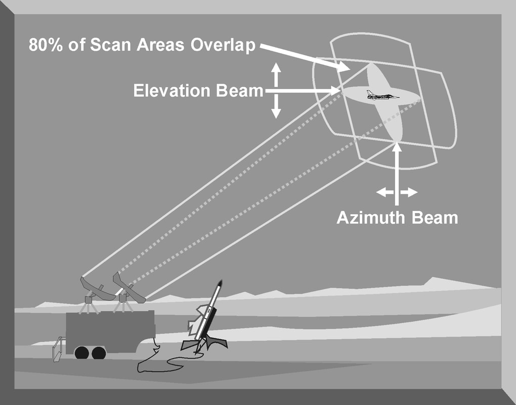
In seeker-aided ground guidance (SAGG) and track-via-missile (TVM) guidance, the target is illuminated by the ground-based radar and the missile receives reflected energy from the target. Unlike conventional semi-active homing, the missile does not generate its own guidance commands. Instead, the missile transmits raw engagement data to the ground-based fire control system (FCS) in order to generate uplink guidance commands. TVM is similar to SAGG; however, additional processing is done on-board the missile prior to transmitting the engagement data to the ground-based FCS. Track-via-missile and seeker-aided ground guidance are two relatively new missile guidance techniques with similar advantages. First, they are extremely accurate at long ranges where the inherent radar tracking errors may be large enough to cause a miss. Second, they can respond very quickly to any actions taken by the target since the missile seeker can track these changes and transmit the new position to the TTR fire control computer. Third, TVM and SAGG can be used with a large and capable fire control computer since most computations are accomplished by the TTR. Fourth, the integration of phased array radar and the powerful TTR fire control computer allows the missile system to engage multiple targets. The Patriot missile battery, for example, can track and engage at least four targets simultaneously. The major disadvantage of track-via-missile and seeker-aided ground guidance is that they are the most complex forms of missile guidance. They require the use of sophisticated computers to combine radar tracking data and data received from the missile. This required hardware is expensive and demands greater maintenance and logistical support. In addition, the missile itself needs to be large enough to store the appropriate hardware for computations and data transfer. A target tracking radar (TTR) or Fire-control radar is designed to provide all the necessary information to guide a missile or aim a gun to destroy an aircraft. Once a target has been detected, either by dedicated search radar or by using an acquisition mode, the TTR is designed to provide accurate target range, azimuth, elevation, or velocity information to a fire control computer. A typical TTR has individual tracking loops to track a target in range, azimuth, elevation, or velocity. The antenna of the TTR is pointed at a single target, and the radar initiates acquisition and target track. TTRs normally employ automatic trackers to continuously measure target data. The range tracking loop employs an early gate/late gate range tracker to maintain automatic range tracking. The azimuth and elevation tracking loops generate error signals to position the antenna and maintain constant target illumination. The velocity tracking loop found on pulse Doppler and CW radars is used to reject clutter and generate accurate target radial velocity information. All this critical information is passed to a fire control computer for weapons employment. The fire control computer is programmed with critical information on the capability of the weapon to be employed. For a missile, the fire control computer is programmed with the aerodynamic and range capabilities of the missile. For antiaircraft artillery (AAA), the fire control computer is programmed with the ballistics for the gun, rate of fire, and tracking rate. The fire control computer uses the precise target information from the TTR and the programmed weapon's parameters to compute a firing solution. Once a firing solution has been computed, the fire control computer either fires the weapon automatically or alerts the operator, who fires the weapon. For missile employment, the fire control computer may continue to provide missile guidance and fusing commands until missile impact or initiation of an active missile guidance mode. For AAA engagement, the fire control computer computes the required lead angle, aims the guns, and initiates firing. To provide the required azimuth and elevation resolution, most TTRs use a high frequency to provide narrow antenna beamwidths for accurate target tracking. High frequency operation also allows the radar to transmit wide bandwidths. To provide the required range resolution, most TTRs employ narrow pulse widths and high pulse repetition frequencies (PRFs) to rapidly update target information. RANGE TRACKING In most TTR applications, the target is continuously tracked in range, azimuth, and elevation. Range tracking can be accomplished by an operator who watches an “A” scope presentation and manually positions a hand wheel to maintain a marker over the desired target return. The setting of the hand wheel is a measure of target range and is converted to a voltage used by the fire control computer. As target speeds and maneuvers increase, the operator may have extreme difficulty maintaining manual target range tracking. To avoid this situation, most TTRs employ an automatic range tracking loop. All pulse TTRs, which includes conical scan, track-while-scan, monopulse, and pulse Doppler radars, employ either a split gate or leading-edge automatic range tracking system. In a TTR, automatic range tracking serves two essential functions: (1) it provides the critical value of target range, and (2) it provides a target acceptance range gate that excludes clutter and interference from other returns. Since radar range is normally the first target discriminator used to initiate automatic target tracking, the second function is essential to the proper operation of the other tracking loops. A range gate circuit is simply an electronic switch that is turned on for a period of time after a pulse has been transmitted. The time delay for switch activation corresponds to a specific range. Any target return that appears inside this range gate is automatically tracked. The most common type of automatic range tracking is accomplished by a split-gate tracker. The automatic range tracking loop attempts to keep the amount of energy from the target return in the early gate and late gate equal. The range tracking error is computed by subtracting the output of the late gate from the output of the early gate. The amount of the range tracking error signal is the difference between the center of the pulse and the center of the range gate. The sign of the error signal determines the direction in which the gates must be repositioned to continue to track the target. Leading-edge range tracking is an electronic protection (EP) technique used to defeat range-gate-pull-off (RGPO) jamming. The leading-edge tracker obtains all range data from the leading edge of the target return. All RGPO cover pulse jamming tends to lag the target return by some increment of time. By differentiating the entire return with respect to time, the target return can be separated from the jamming pulse. Employing a split-gate tracker electronically positioned at the initial pan, or leading edge, of the returning pulse, the range tracking loop can track the target return and ignore any jamming signals. The range tracking loop then uses split-gate tracking logic to determine the magnitude and direction of range tracking errors and reposition the range gate. The width of the tracking gate is an important radar design consideration. The range gate should be sufficiently narrow to effectively isolate the target from other returns at different ranges. It should be wide enough to allow sufficient energy from the target echo to be displayed. The width of the range tracking gate is normally equal to the pulse width of the radar. Nearly all range tracking gates employ some form of automatic gain control (AGC). AGC is designed to limit target clutter and glint. It is also designed to avoid excessive false alarms. TRACK-WHILE-SCAN (TWS) TWS is a combined search and tracking mode that sacrifices the continuous target observation capability of the dedicated tracker in return for the ability to monitor a finite sector of airspace. This is accomplished while maintaining tracks on multiple targets moving through the covered airspace. There are two types of radar systems capable of TWS operation: conventional and phased array. Conventional track-while-scan threat radars use two separate antennas to generate two separate beams. These beams operate at two different frequencies and are sectored so they overlap the same region of space. This overlap area provides a tracking area for a single target. One beam is sectored in the vertical plane to give range and elevation. The other beam is sectored in the horizontal plane to provide range and azimuth. Each beam scans its sector at a rate of 5 to 50 times per second. This provides a rapid update on target range, azimuth, and elevation. TRACK-WHILE-SCAN (TWS) TWS is a combined search and tracking mode that sacrifices the continuous target observation capability of the dedicated tracker in return for the ability to monitor a finite sector of airspace. This is accomplished while maintaining tracks on multiple targets moving through the covered airspace. There are two types of radar systems capable of TWS operation: conventional and phased array. Conventional track-while-scan threat radars use two separate antennas to generate two separate beams. These beams operate at two different frequencies and are sectored so they overlap the same region of space. This overlap area provides a tracking area for a single target. One beam is sectored in the vertical plane to give range and elevation. The other beam is sectored in the horizontal plane to provide range and azimuth. Each beam scans its sector at a rate of 5 to 50 times per second. This provides a rapid update on target range, azimuth, and elevation. The two TWS antennas generate their beams using an electromechanical principle. Each antenna provides inputs to its own display and provides angle and range information for all targets in the coverage of the radar. The display from the elevation beam is calibrated in range and elevation, while the display from the azimuth beam is calibrated in azimuth and range. Operators position a cursor over the returns on these displays using range as the primary parameter. Once a target has been designated for engagement, the radar automatically attempts to keep the tracking axis of the radar beams centered on the target. Once the target is designated by the operator, the range gate is enabled and tracks the target using a split-gate tracker. The azimuth and elevation tracking loops receive information only from targets inside the range gate. As the beams scan across the target, a burst of pulse returns is received that have an amplitude envelope corresponding to the beam pattern. The azimuth tracker is typically a split-gate tracker, identical in concept to a split-gate range tracker. However, range delay time is replaced by azimuth scan time. The azimuth tracker uses a left gate and right gate. Each gate integrates its share of the target return to generate a voltage/time value. When the azimuth gate is centered on the target, the areas are equal and the error signal (right gate minus left gate) is zero. The azimuth tracking loop sends signals to the antenna servos to keep the target centered in the scan area. Elevation tracking is accomplished in the same manner by using an up gate and a down gate. The elevation tracking loop also sends signals to the antenna servos to keep the target centered in the scan area. Once the target is designated and the radar is automatically keeping the radar return centered in the tracking area, target range, azimuth, and elevation information is sent to a fire control computer. The radar continues to provide information on other targets in the scan area. The fire control computer indicates the firing solution has been achieved for the designated target, and a missile is launched. The radar tracks the target and the missile and provides in-flight corrections to the missile right up to the moment of missile impact. These corrections are based on both target and missile azimuth, range, and elevation information. Information is passed to the missile from a dedicated antenna on the radar to special antennas on the missile. Commands from the radar to the missile are called uplink guidance commands. Information from the missile back to the radar and fire control computer is called downlink information. The advantages of a conventional TWS radar include the following:
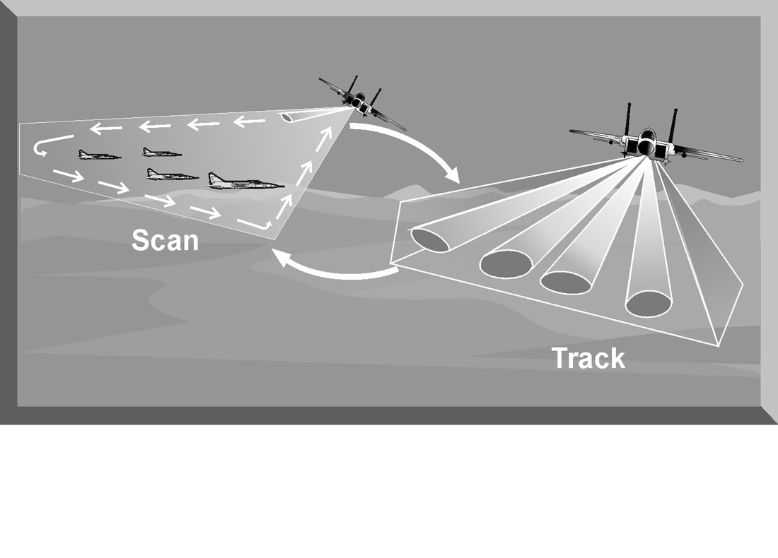
The primary disadvantages of a conventional TWS radar include: (1) A large resolution cell due to the wide azimuth and elevation beams, and (2) Vulnerability to modulation jamming based on the scan rate of the independent beams. Many modern radars employing a planar or phased array antenna system have a TWS mode. The radar does not really track and scan simultaneously, but rapidly switches between search and track The most common air-to-air radar system uses a planar array antenna. In the scan mode, the radar antenna generates a pencil beam and uses a raster scan to detect targets in the search area. Targets detected are presented to the pilot on the aircraft's radar display. In the track mode, the antenna generates multiple beams to illuminate individual targets. The radar typically uses monopulse or pulse Doppler techniques to update target range, azimuth, elevation or velocity.The radar initiates a track file on each detected target that contains all current data on the target and an estimate of future target position. As the radar switches between track and scan modes, target parameters are updated in the tracking loop. The new target information is compared to the predicted information in the measurement data processing cell. If the two sets of data agree within certain limits, target position and information are updated. This process is called gating. If the updated target information does not correspond to the predicted values, the information is sent to the correlation processor. The correlation processor attempts to resolve the conflict based on further refinement of target data. If the correlation processor cannot assign the target parameters to an existing track file, a new track file is generated and displayed. The obvious advantage of a planar/phased array TWS radar is that it can search a large volume of airspace while tracking individual targets. The number of targets that can be tracked is limited by the number of beams the radar can generate. Planar/phased array radars have increased peak and average power when compared to pulse radar systems. Since the radar beam of a planar/phased array radar is electronically controlled and can rapidly change beams and scans, it is resistant to many jamming techniques. The primary disadvantages of a planar/phased array TWS radar include its complexity, cost, and reliance on computer processing. LOBE-ON-RECEIVE-ONLY (LORO)
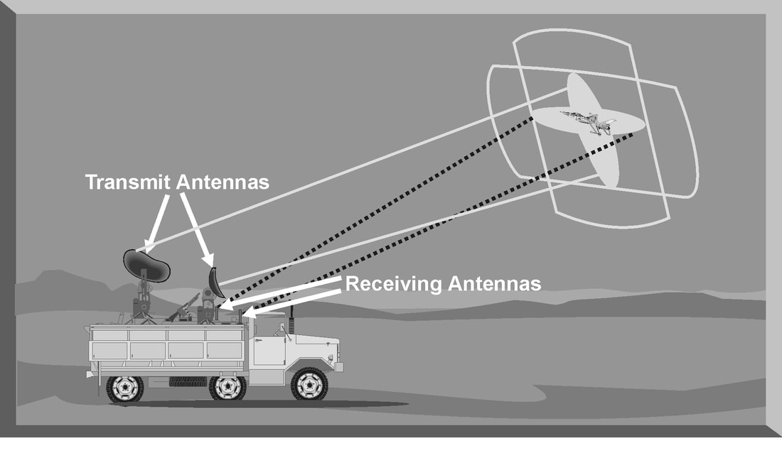
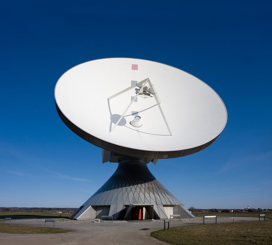
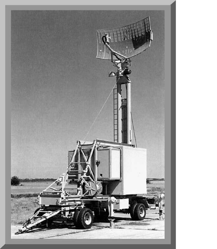
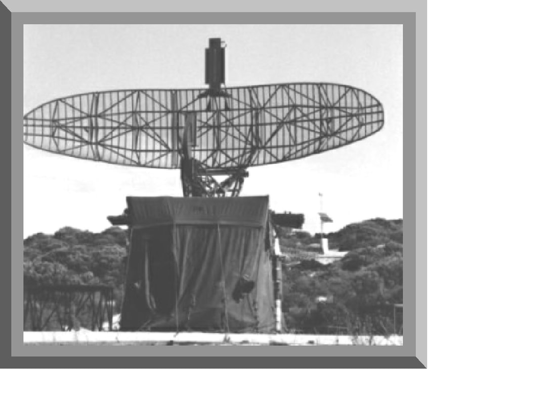
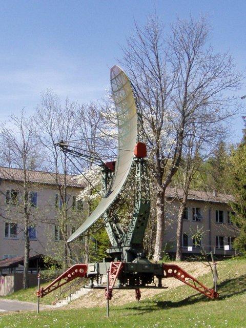
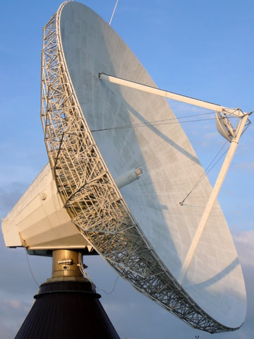
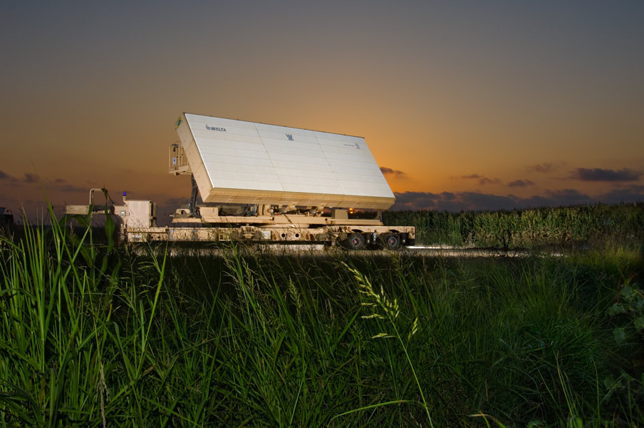
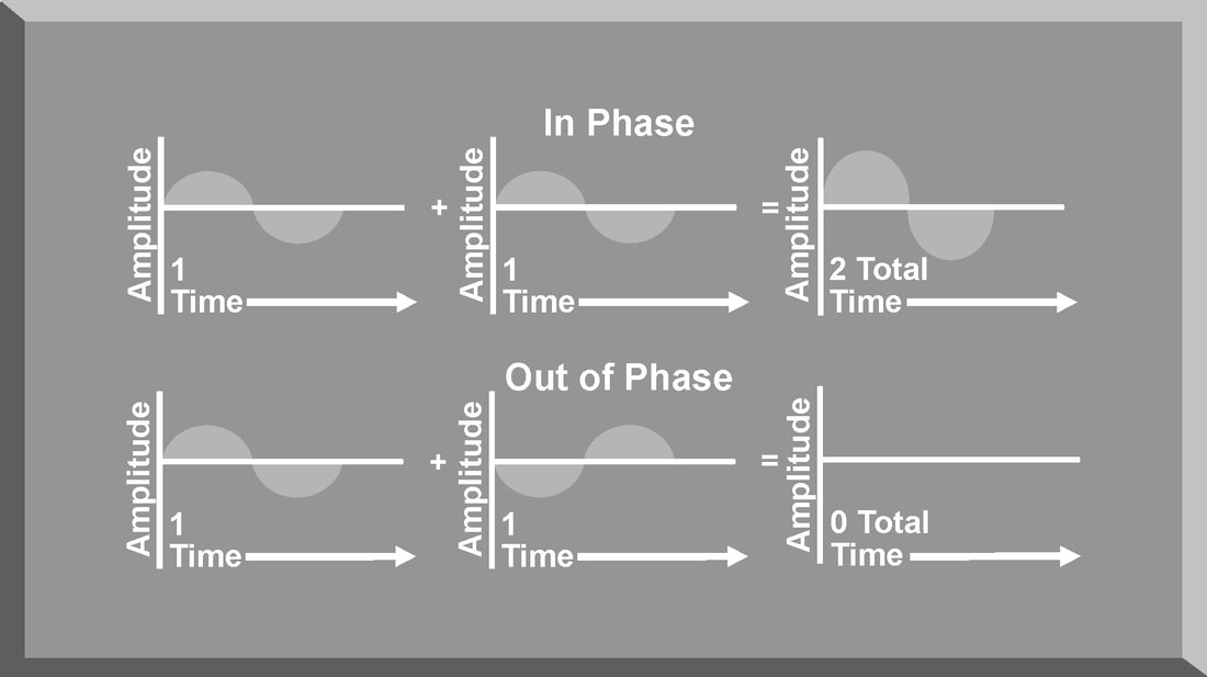
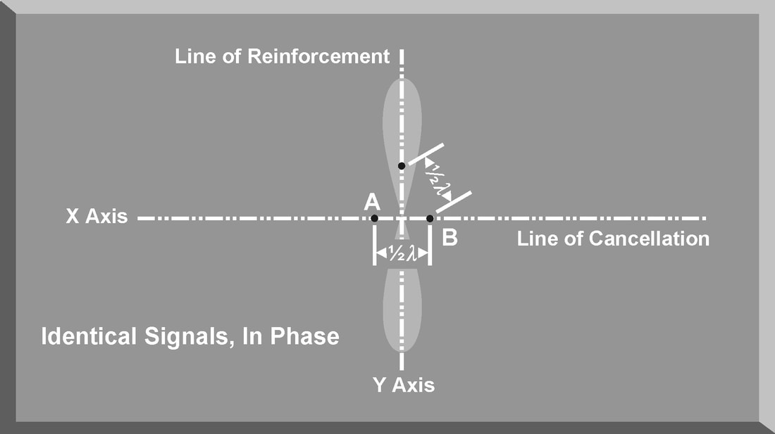
LORO is a mode of radar operation developed as an EP feature for a track-while scan radar. LORO can be employed by any radar that has the capability to passively track a target. In a LORO mode, the radar transmits a continuous signal from a set of illuminating antennas. This continuous signal hits the target, and the return echo is received by a different set of receive antennas . The receive antennas are passive and generate azimuth and elevation tracking signals by electronically scanning the reflected signal. The tracking signals are sent to the antenna servos to keep the illuminating antennas pointed at the target and centered in the receive antenna tracking area. The range tracking circuit uses the time delay between the transmission and reception of the illuminating antenna signals. A split-gate tracker is used to provide range tracking. The illuminating antennas used in the LORO mode have very narrow beam widths and transmit at a high power level. This reduces the effectiveness of noise jamming techniques against a radar employing a LORO mode. In addition, the continuous signal from the illuminating antennas negate the effectiveness of most angle deception jamming techniques designed to defeat TWS radars. These specialized jamming techniques exploit the scan rate of TWS antennas. In the LORO mode, the illuminating antennas do not have a scan rate. The limited effectiveness of both noise and deception jamming techniques is the major advantage of the LORO mode. The LORO mode also provides a track-on-jam (TOJ) capability to exploit noise jamming techniques. In a TOJ mode, the receive antennas passively track any detected noise jamming signals. The radar assumes that the most intense jamming signal is the target. The receive antennas process the strongest jamming signal as if it were a target echo from the transmit antenna signal. The receive antennas generate azimuth and elevation tracking signals to keep the jamming signal centered in the tracking area. The TOJ mode does not provide target range. The function of the antenna during transmission is to concentrate the radar energy from the transmitter into a shaped beam that points in the desired direction. During reception, or listening time, the function of the antenna is to collect the returning radar energy, contained in the echo signals, and deliver these signals to the receiver. Radar antennas are characterized by directive beams that are usually scanned in a recognizable pattern. The primary antenna types in use today fall into three categories: parabolic, Cassegrain, or phased array antennas. Additionally, the method radar antennas employ to sample the environment is a critical design feature of the radar system. The scan type selected for a particular radar system often decides the employment of that radar in an integrated air defense system (lADS). The process the radar antenna uses to search airspace for targets is called scanning or sweeping. PARABOLIC ANTENNA One of the most widely used radar antennas is the parabolic reflector. The parabola-shaped antenna is illuminated by a source of radar energy, from the transmitter, called the feed. The feed is placed at the focus of the parabola, and the radar energy is directed at the reflector surface. Because a point source of energy, located at the focus, is converted into a wavefront of uniform phase, the parabola is well suited for radar antenna applications. By changing the size and shape of the parabolic reflecting surface, a variety of radar beam shapes can be transmitted. The antenna depicted in Figure generates a nearly symmetrical pencil beam that can be used for target tracking. Elongating the horizontal dimensions of the parabolic antenna creates a radar antenna called the parabolic cylinder antenna. The pattern of this antenna is a vertical fan-shaped beam. Combining this antenna pattern with a circular scan technique creates a radar system well suited for long-range search and target acquisition. Elongating the vertical dimensions of the parabola creates a radar antenna that generates a horizontal fan-shaped beam with a small vertical dimension. This type of antenna is generally used in height-finding radar systems. Another variation of the basic parabolic antenna includes using an array of multiple feeds instead of a single feed. This type of parabolic antenna can produce multiple radar beams, either symmetrical or asymmetrical, depending on the angle and spacing of the individual feeds. CASSEGRAIN ANTENNA A Cassegrain antenna uses a two-reflector system to generate and focus a radar. The primary reflector uses a parabolic contour, and the secondary reflector, or subreflector, has a hyperbolic contour. The antenna feed is located at one of the two foci of the hyperbola. Radar energy from the transmitter is reflected from the subreflector to the primary reflector to focus the radar beam. Radar energy returning from a target is collected by the primary reflector and reflected as a convergent beam to the subreflector. The radar energy is rereflected by the subreflector, converging at the position of the antenna feed. The larger the subreflector, the closer it can be to the primary reflector. This reduces the axial dimensions of the radar but increases aperture blockage due to the subreflector. A small subreflector reduces aperture blockage, but it must be positioned at a greater distance from the primary reflector. To reduce the aperture blockage by the subreflector and to provide a method to rapidly scan the radar beam, the flat plate Cassegrain antenna was developed. The fixed parabolic reflector is made up of parallel wires spaced less than a half wavelength apart and supported by a low-loss dielectric material. This makes the fixed parabolic reflector polarization sensitive. It will completely reflect one type of linear polarization and be transparent to the orthogonal polarization. The fixed antenna feed, in the middle of the moveable mirror, transmits a radar signal polarized to be reflected by the parabolic reflector. The moveable mirror is constructed as a twist reflector that changes the polarization of the radar signal by 90°. The signal from the feed is reflected by the parabolic reflector to the mirror, which rotates the polarization 90°. This rotation makes the transmitted signal transparent to the parabolic reflector, and the signal passes through with minimal attenuation. The radar beam can be scanned over a wide area by rotating the moveable mirror. A deflection of the mirror by the angle Ɵ results in the beam scanning through an angle of 2Ɵ. The geometry of the Cassegrain antenna is especially well suited for monopulse tracking radar applications. Unlike the parabolic antenna, the complex feed assembly required for a monopulse radar can be placed behind the reflector to avoid aperture blocking. PHASED ARRAY ANTENNA The phased array radar is a product of the application of computer and digital technologies to the field of radar design. A phased array antenna is a complex arrangement of many individual transmitting and receiving elements in a particular pattern. A phased array antenna can, in effect, radiate more than one beam from the antenna by using a computer to rapidly and independently control groups of these individual elements. Multiple beams and computer processing of radar returns give the phased array radar the ability to track-while-scanning and engage multiple targets simultaneously. Phased array radar uses the principle of radar phase to control the individual transmitting and receiving elements. When two transmitted frequencies are in-phase, their amplitudes add together, and the radiated energy is doubled. When two transmitted frequencies are out-of-phase, they cancel each other. Phased array radars use this principle to control the shape of the transmitted radar beam. Phase relationships and antenna element spacing determine the orientation of the transmitted beam. For eg, antenna elements A and B are separated by one-half wavelength and are radiating in-phase, that is, when one is at the positive peak, the other is also at a positive peak. Since the elements are one-half wavelength apart, when the positive peak radiated by A reaches B, B will be radiating a negative peak. As the peaks propagate along the X axis, they will cancel each other out. The total radiated power along that axis will be zero. Along the Y axis, however, the positive peaks from A will add to the positive peaks from B, causing the total radiation along this axis to be at its maximum value. This type of array is called a “broadside array” because most of the radiation is in the direction that is broadside to the line of the antenna array. The computer controlling the phase of the signal delivered to each transmitting and receiving element of a phased array antenna controls the direction and shape of the radiated beam. By shifting the phase of the signals between 0° and 180°, the beam sweeps. This is the basic means of producing an antenna scan. In addition, the amplitude, or power, of the signal applied to each element can be varied to control the sidelobes. This alters the shape of the beam which affects the range capability and angular resolution of the radar. Depicts a variation of the phased array antenna, known as a planar array antenna. A planar array antenna uses transmit and receive elements in a linear array, but, unlike the phased array radar, the elements are smaller and are placed on a movable flat plate. The ability to simultaneously track several targets is one advantage of this type of radar. ANTENNA GAIN The most important characteristic of any type of antenna is antenna gain. Antenna gain is a measure of the ability of an antenna to concentrate energy in the desired direction. Antenna gain should not be confused with receiver gain, which is designed to control the sensitivity of the receiver section of a radar system. There are two types of antenna gain: directive and power. The directive gain of a transmitting antenna is the measure of signal intensity radiated in a particular direction. Directive gain is dependent on the shape of the radiation pattern of a specific radar antenna. The directive gain does not take into account the dissipative losses of the antenna. Directive gain is computed using Equation GD = Maximum radiation intensity / Average radiation intensity The power gain does include the antenna dissipative losses and is computed using Equation Power gain = max radiation intensity/ Radiation intensity of an isotropic antenna The term isotropic antenna describes a theoretical spherical antenna that radiates with equal intensity in all directions. This results in a spherical radiation pattern. The power density for any point on an isotropic antenna is the radiation intensity and can be calculated by dividing the total power transmitted (PT) by the total surface area of the sphere, Power density (Isotropic Antenna) = PT (watts)/ 4*Pie*r2 (Cm2) The radiation pattern of an isotropic, or spherical, antenna would provide neither azimuth nor elevation resolution and would be unusable for radar applications. To provide azimuth and elevation resolution, a practical antenna must focus the radar energy. The power density of a practical antenna differs from the isotropic antenna only in terms of antenna gain (G). Power Density (Practical antenna) = PT*G/ 4*pie*r2 The actual power gain (G) of a practical antenna can be calculated by using Equation G= 4*pie*Ae/lamda Ae= effective area of aperture Lamda = Wavelength of the radar POWER DENSITY
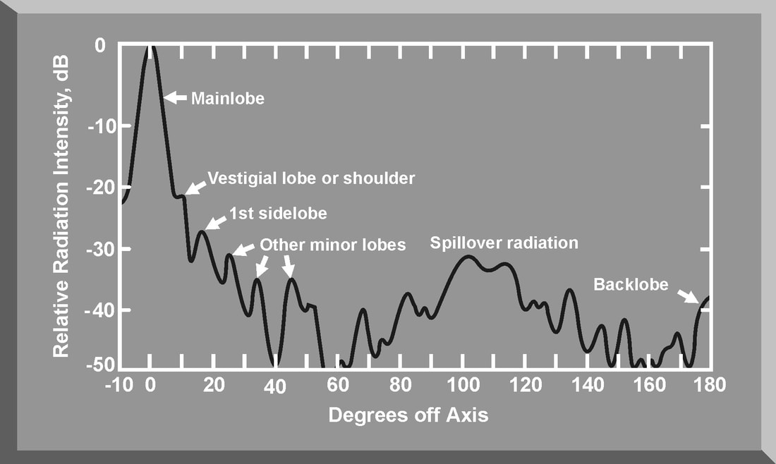
The power density and gain of an antenna are a function of the antenna pattern of a radar system. Figures illustrate the antenna pattern of a typical parabolic antenna. Most of the power density of the radar is concentrated in the main beam. However, since the radar is not a perfect reflector, some radar energy is transmitted in the sidelobes. In addition, there is spillover radiation due to the energy radiated by the feed that is not intercepted by the reflector. Finally, the radar has a back lobe caused by diffraction effects of the reflector and direct signal leakage. Sidelobes and backlobes are all undesirable radiations that adversely affect the maximum radar range and increase the vulnerability of the radar to certain jamming techniques.
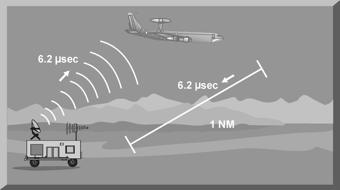
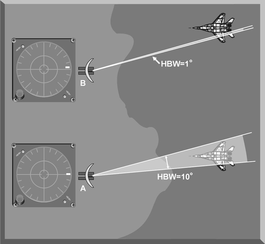
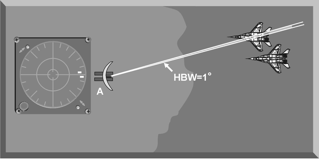
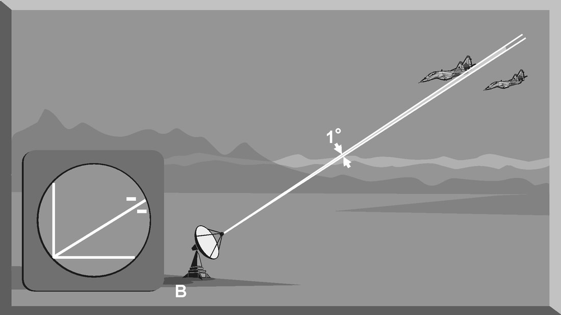
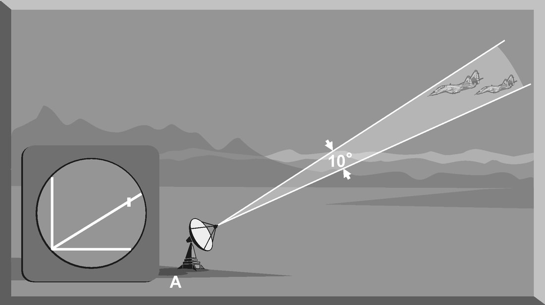
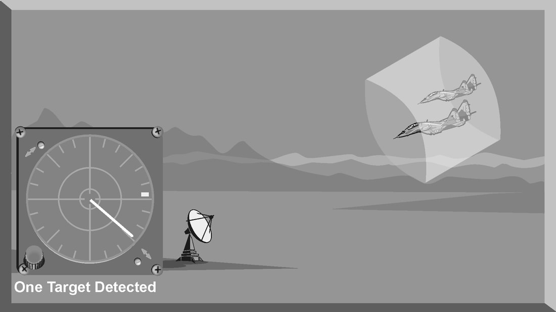
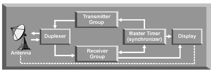
Introduction The primary purpose of radar systems is to determine the range, azimuth, elevation, or velocity of a target. The ability of a radar system to determine and resolve these important target parameters depends on the characteristics of the transmitted radar signal. This chapter explains the relationship of radar frequency (RF), pulse repetition frequency (PRF), pulse width (PW), and beam width to target detection and resolution. Radar range A basic pulse radar system consists of four fundamental elements: the transmitter, the receiver, the antenna, and the synchronizer, or master timer. Transmitter The transmitter, through the antenna, sends out a pulse of RF energy at a designated frequency. The presence of a target is revealed when the RF energy bounces off the target, returns to the radar antenna, and goes into the receiver. The master timer measures the time between the transmission of a pulse and the arrival of a target echo. RF energy travels at the speed of light (c) which is 3 x 10⁸ meters per second. Target range can be computed by using the basic radar range determination equation. Target Range = (measured Time * Speed of light)/2 Another useful measurement is the radar mile, which is the round trip time for an RF wave to travel to and from a target one nautical mile away. In simple terms the time required for a radar pulse to travel a distance of one nauticalmile and then return to the radar receiver. One radar nautical mile is equal to approximately 12.367 μs Measured time = (Target Range *2)/ c = (1853 meters *2) / 300000000 = 12.367 Micro Seconds. Radar timing is usually expressed in microseconds. To relate radar timing to distances traveled by radar energy, you should know that radiated energy from a radar set travels at approximately 984 feet per microsecond. With the knowledge that a nautical mile is approximately 6,080 feet, we can figure the approximate time required for radar energy to travel one nautical mile using the following calculation: A pulse-type radar set transmits a short burst of electromagnetic energy. Target range is determined by measuring elapsed time while the pulse travels to and returns from the target. Because two-way travel is involved, a total time of 12.36 microseconds per nautical mile will elapse between the start of the pulse from the antenna and its return to the antenna from a target. This 12.36 microsecond time interval is sometimes referred to as a RADAR MILE, RADAR NAUTICAL MILE, or NAUTICAL RADAR MILE 1 Radar Kilometer = 6.66 Micro Sec The range in kilometers to an object can be found by measuring the elapsed time during a round trip of a radar pulse and dividing this quantity by 6.66. The range in nautical miles to an object can be found by measuring the elapsed time during a round trip of a radar pulse and dividing this quantity by 12.36. A limitation on radar detection range is the concept of a second time around echo. A second time around echo occurs when a target echo associated with a particular radar pulse arrives at the antenna after another radar pulse has been transmitted. The radar master timer always assumes the target echo is associated with the last pulse transmitted. This makes the target echo ambiguous in range. Example: - Radar pulse A takes 372 microseconds to travel to the target and return. Using the range determination equation, actual target range is 30 nautical miles (nm). However, before the target echo returns to the antenna, radar pulse B is transmitted. The master timer associates the target echo of pulse A with radar pulse B, and calculates a target range of 10 nm. This ambiguous and false range is displayed to the operator. Modern radars are designed with second time around echo as important functional modes, and engineers have developed ways to resolve the ambiguity. Range resolution A critical aspect of range determination is range resolution. Range resolution is the ability of radar to separate two targets that are close together in range and are at approximately the same azimuth. The range resolution capability is determined by pulse width. Pulse width is the time that the radar is transmitting RF energy. Pulse width is measured in microseconds. A radar pulse in free space occupies a physical distance equal to the pulse width multiplied by the speed of light, which is about 984 feet per microsecond. If two targets are closer together than one-half of this physical distance, the radar cannot resolve the returns in range, and only one target will be displayed. The range resolution of the radar is usually expressed in feet and can be computed using Equation Range Resolution = (pulse width *984 ft)/2 It is the minimum separation required between two targets in order for the radar to display them separately on the radar scope. Azimuth Determination The beamwidth of a radar system is the horizontal and vertical thickness of the radar beam. Beamwidth depends on antenna design and is normally measured in degrees from the center of the beam to the point at which the power drops off by half. This half-power point is -3 dB in power drop-off. Beamwidth governs the azimuth and elevation accuracy and resolution capability of a radar system in the same way that pulse width governs radar range accuracy and resolution. In order for a radar system to figure out target azimuth, the antenna must be aligned with a point of reference and pointed at the target during the transmission and reception of several pulses of radar energy. If the antenna is referenced to true North, the azimuth of the target can be measured relative to true North. Azimuth determination is based on the position of the antenna when the target is being illuminated. To provide accurate azimuth determination over a large area, many types of radar employ a narrow beam and scan the antenna in a predictable pattern. The most common scan pattern is a 360° circular scan at a constant rate. The plan position indicator (PPI) radar scope display is normally associated with this scan pattern. As the radar beam sweeps, a target is detected and displayed. The position of the antenna, when the target is displayed, shows the relative azimuth. The azimuth accuracy of a radar system is determined by the horizontal beamwidth (HBW). Consider the following Figure, radar system A has a horizontal beamwidth of 10°. As the beam sweeps, the target is illuminated for as long as it is in the beam. This means that the target covers 10° in azimuth on the PPI scope. Radar system B has a beamwidth of 1°. A target displayed on the PPI scope will cover 1° in azimuth. The narrower the horizontal beamwidth, the better the azimuth accuracy. Azimuth resolution is the ability of radar to display two targets flying at approximately the same range with little angular separation, such as two fighters flying line-abreast tactical formation. The azimuth resolution capability is usually expressed in nautical miles and corresponds to the minimum azimuth separation required between two targets for separate display. Azimuth resolution depends on the horizontal beamwidth of the radar. The radar system in Figure has a horizontal beamwidth of 10°. The two targets are so cIose in azimuth that the return echoes are blended into one return. The radar system in the next Figure has a horizontal beamwidth of 1°. The radar beam not only hits the targets, but passes between them without causing a return. This allows the radars to display two distinct radar returns. A small horizontal beamwidth improves azimuth resolution. Azimuth resolution, in nautical miles, can be computed using Equation Azimuth resolution = (Horizontal Beam width * Range) 60 Notice that this equation is the “60 to 1 rule” used for navigation. A 1°beamwidth will yield a one-mile-wide cell at 60 nautical miles. Elevation determination Since a radar beam is three-dimensional, the vertical beamwidth is the primary factor in determining altitude resolution capability. Altitude resolution is the ability of radar to display two targets flying at approximately the same range and azimuth with little altitude separation, such as two fighters flying a vertical stack formation. The altitude resolution capability is usually expressed in feet and corresponds to the minimum altitude separation required between two targets for separate display. The radar system in Figure has a vertical beamwidth of 10°. The two targets are so close in altitude that the return echoes depicted on the range height indicator (RHI) are blended into one. The radar system depicted in Figure has a vertical beamwidth of 1°.This small beam not only hits the targets, but passes between them without causing a return. This allows the radar to display two distinct targets. Altitude/elevation resolution, in thousands of feet, can be computed using Altitude Resolution = (Vertical beam width * Range)/ 60 Radar resolution cell A radar's pulse width, horizontal beamwidth, and vertical beamwidth form a three dimensional resolution cell (RC) . A resolution cell is the smallest volume of airspace in which a radar cannot determine the presence of more than one target. The resolution cell of a radar is a measure of how well the radar can resolve targets in range, azimuth, and altitude. The horizontal and vertical dimensions of a resolution cell vary with range. The closer to the radar, the smaller the resolution cell. The physical dimensions of a radar's resolution cell can be computed. For a radar with a pulse width of 1 microsecond, a horizontal beamwidth of 1°, and a vertical beamwidth of 10°, the formulas for range resolution, azimuth resolution, and altitude resolution can be used to compute the dimensions of the resolution cell. For example , at a target range of 10 nm, the physical dimensions of the radar's resolution cell are 492 feet in range, by 1000 feet in azimuth, and 10,000 feet in altitude. These figures can be confirmed by using above Equations. Based on these computations, two, or more, aircraft flying a trail formation closer than 492 feet would be displayed as a single target. Two, or more, aircraft flying line abreast closer than 1000 feet would be displayed as a single target. Two, or more, aircraft flying a vertical stack closer than 10,000 feet would be displayed as a single target. This also shows that the shorter the pulse width, the better the range resolution capability of a radar system. The narrower the horizontal beamwidth, the better the azimuth resolution capability. The narrower the vertical beamwidth, the better the altitude resolution capability. Another type of resolution is velocity resolution. For a Doppler radar aircraft flying within the conventional resolution cell described above can be distinguished as separate targets if they have enough speed differentials. Pulse Doppler Velocity Determination To fully understand how a pulse Doppler radar determines target velocity, it is necessary to know more about the pulsed waveform. To generate a pulse modulated wave, a continuous carrier sine wave, like the output from a CW radar, is combined with a rectangular wave, like that of a pulse radar, to produce the pulse modulated waveform. Mathematically, any waveform other than a sine wave is composed of many different pure sine waves added in the proper amplitude and phase relationships. In a pulsed modulated waveform, the sine waves correspond to the fundamental frequency, which is the PRF, and the sum of all harmonics in the proper amplitude and phase. The frequency of the harmonic is the basic frequency plus or minus a multiple of the PRF. Below Figure is a plot of the harmonic content of a pulse modulated waveform operating at a carrier frequency of 2800 megahertz (MHz) with a PRF of 1 MHz. Note the loops of frequencies on either side of the carrier frequency. These are the additions and subtractions of all the frequencies in the rectangular pulse to the carrier frequency. The important thing to remember is that there are many frequencies present, and a pulse Doppler radar must deal with a crowded frequency spectrum. This becomes even more important when one considers the fact that every frequency present will experience a Doppler shift when it is reflected by a moving target. The individual frequencies shown are called spectral lines. For a pulse Doppler radar to accurately measure velocity, it must compare the frequency change, or Doppler shift, between the carrier frequency and the frequency returning from the target. It is a difficult task for the radar to differentiate between the returning carrier and all the harmonic frequencies. The radar differentiates between the returning carrier frequencies and all other harmonic frequencies by using clutter cancellers, or filters, at the known harmonic frequencies. The radar cannot process frequencies cancelled by these filters. The filters create “blind speeds” for the radar. The closer together the spectral lines, the more “blind speeds” the radar will have. Since the position of the harmonics in relation to the carrier frequency is based on PRF, the number of blind speeds can be reduced by changing the PRF of the radar. The higher the PRF, the wider the spacing of the spectral lines and the fewer blind speeds due to selective clutter canceling. However, a high PRF increases the problem of range ambiguities. Most modern pulse Doppler radars employ a medium and high PRF mode. Medium PRF equates to fewer range ambiguities but more blind speeds. High PRF has fewer blind speeds but more range ambiguities To separate the returning target frequency shifts from all other frequencies in the returning waveform, the pulse Doppler radar employs filters to cancel the known harmonic frequency shifts. In addition, the radar cancels out all returns with no frequency shift, which equates to canceling all returns with no movement relative to the radar. However, if the radar has too many clutter filters, this creates multiple blind speeds, and targets will be missed. Basic Radar Equation The basic radar equation relates the range of a radar system to the characteristics of the transmitter, receiver, antenna, and the target. The radar equation provides a means not only to figure out the maximum range of a particular radar system, but it can be used to understand the factors that affect radar operation. In this section, the simple forms of the radar equation are developed, starting with the power density of the transmitting antenna to the power received by the receiving antenna. Power density is the power of a radio wave per unit of area normal to the direction of propagation. The power density generated by a practical antenna can be expressed Power density from Antenna = (PT*G) / (4*pi*r2) PT = Transmitted Power G = Antenna Gain R = Radius of the antenna As the radar beam propagates through space, it arrives at a target at some range (R) from the antenna. As the radar beam travels through space, the wavefront of the beam expands to a very large cross-sectional area, especially in relation to the target dimensions. The power density of the radar beam, across this wide area, at the target, is detailed in the below Equation Power Density at Target = (PT*G) / (4*pi*r2) PT = Transmitted Power G = Antenna Gain R = Range to the Target Since the cross-sectional area of the radar beam is so large, only a small portion of the total power in the beam can be reflected toward the antenna. The rest of the radar energy continues through space and is dissipated, absorbed, or reflected by other targets. The small portion of the radar beam that hits the target is reradiated in various directions. The measure of the amount of incident power intercepted by the target and reradiated back in the direction of the antenna depends on the radar cross section (RCS) of the target. Equation details the power density of the target echo signal reflected back to the radar antenna is below Power Density at Antenna = [(PT*G) / (4*pi*r2)] * [RCS / (4*pi*r2)] PT = Transmitted Power G = Antenna Gain R = Range to the Target RCS= Radar Cross Section As the target echo reaches the antenna, part of the echo is captured by the antenna based on the effective aperture (Ae). Equation details the actual signal power received by the radar system follows. This is one form of the basic radar equation and is the signal strength of a radar return from a specific target at range (R) from the radar. Signal Power Density(S) = [(PT*G*RCS*Ae) / ((4*pi) 2*r4)] PT = Transmitted Power G = Antenna Gain R = Range to the Target RCS= Radar Cross Section Ae = Effective aperture A detailed analysis of this equation is not required to draw some basic conclusions about the factors affecting the detection of an aircraft. If any factor in the numerator, such as transmitted power, is increased by a factor of three, the signal received by the radar will increase by only 30 percent. This clearly shows why radar system operation is characterized by the transmission of megawatts of power and the reception of microwatts of returning power. In addition, this equation shows that the most critical factor in determining radar detection is target range. The maximum radar range (RMAX) occurs when the signal power density received just equals the minimum detectable signal (SMIN) for the receiver. Solving Equation for range, and substituting SMIN, yields the basic radar equation for RMAX for a specific target. This is another form of the basic radar equation. R max = [(PT*G*RCS*Ae) ¼] / ((4*pi) 2* S min)] PT = Transmitted Power G = Antenna Gain R = Range to the Target RCS= Radar Cross Section Ae = Effective aperture The individual components of a radar determine the capabilities and limitations of a particular radar system. The characteristics of these components also determine the countermeasures that will be effective against a specific radar system. Here we will discuss the components of basic pulse radar, continuous wave (CW) radar, a pulse Doppler radar, and monopulse radar.
PULSE RADAR SYSTEM The most common type of radar design is the pulse radar system. The name describes a process of transmitting discrete bursts of RF energy at the frequency of the radar system. The time that pulses are transmitted determines the pulse repetition frequency (PRF) of the radar system. A pulse radar system can figure out range and azimuth. Range is determined by the time that it takes a pulse to go to a target and return. Target azimuth is determined by the relative position, or antenna orientation, when the pulse strikes the target. INTRODUCTION
Every radar produces a radio frequency (RF) signal with specific characteristics that differentiate it from all other signals and define its capabilities and limitations. Pulse width (pulse duration), pulse recurrence time (pulse repetition interval), pulse repetition frequency, and power are all radar signal characteristics determined by the radar transmitter. Listening time, rest time, and recovery time are radar receiver characteristics. An understanding of the terms used to describe these characteristics is critical to understanding radar operation. PULSE WIDTH (PW) PW, sometimes called pulse duration (PD), is the time that the transmitter is sending out RF energy. PW is measured in microseconds. It has an impact on range resolution capability, that is, how accurately the radar can discriminate between two targets based on range. The pulse width of the transmitted signal is to ensure that the radar emits sufficient energy to allow that the reflected pulse is detectable by its receiver. The amount of energy that can be delivered to a distant target is the product of two things; the output power of the transmitter, and the duration of the transmission. Therefore, pulse width constrains the maximum detection range of a target. Weapons-control radar, which requires great precision, should be able to distinguish between targets that are only yards apart. Search radar is usually less precise and only distinguishes between targets that are hundreds of yards or even miles apart. Resolution is usually divided into two categories; range resolution and bearing resolution. Range resolution is the ability of a radar system to distinguish between two or more targets on the same bearing but at different ranges. The degree of range resolution depends on the width of the transmitted pulse, the types and sizes of targets, and the efficiency of the receiver and indicator. Pulse width is the primary factor in range resolution. A well-designed radar system, with all other factors at maximum efficiency, should be able to distinguish targets separated by one-half the pulse width time. PULSE RECURRENCE TIME (PRT) Pulse recurrence time is also known as pulse repetition time. PRT is the time required for a complete transmission cycle. This is the time from the beginning of one pulse of RF energy to the beginning of the next. PRT is measured in microseconds. PRT is the same as pulse repetition interval (PRI), which is used in radar warning receivers and other electronic warfare support (ES) assets to discriminate between radar systems. It also affects maximum radar range. ELECTRONIC warfare (EW) is the systems approach to the exploitation and control, to the maximum extent possible, of the electromagnetic (EM) spectrum. It is an important capability that can advance desired military, diplomatic, and economic objectives or, conversely, impede undesired ones. The use by an adversary of the EM spectrum for communications, navigation, and radar functions can be challenged by the techniques and technology of EW systems. In a military application, EW provides the means to counter, in all battle phases, hostile actions that involve the EM spectrum—from the beginning when enemy forces are mobilized for an attack, through to the final engagement. EW exploits the EM environment by sensing and analyzing an adversary’s application of the spectrum and imposing appropriate countermeasures (CMs) to hostile spectrum use. CHARACTERISTICS OF RF RADIATION
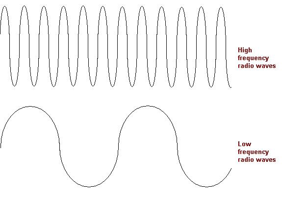
In order for a radar system to determine range, azimuth, elevation, or velocity data, it must transmit and receive electromagnetic radiation. This electromagnetic radiation is referred to as radio frequency (RF) radiation. RF transmissions have specific characteristics that determine the capabilities and limitations of a radar system to provide these target discriminants, based on an analysis of the characteristics of the target return. The frequency of transmitted RF energy affects the ability of a radar system to analyze target return, based on time, to determine target range. RF frequency also affects the ability of the transmitting antenna to focus RF energy into a narrow beam to provide azimuth and elevation information. The wavelength and frequency of the transmitted RF energy impact the propagation of the radar signal through the atmosphere. The polarization of the RF signal affects the amount of clutter the radar must contend with. The ability of a radar system to use the Doppler effect in analyzing the radar return impacts the velocity discrimination capability of the radar. FREQUENCY The output signal from a typical radar system has several important characteristics that affect the capabilities and limitations of radar systems. The first characteristic considered is usually RF. The frequency of the transmitted signal is the number of times per second the RF energy completes one cycle. The basic unit of measurement is the hertz (Hz). One hertz equals one cycle per second. Most radar has an RF in the millions of hertz. |
AuthorPalash Choudhari Archives
June 2021
Categories
All
|


 RSS Feed
