|
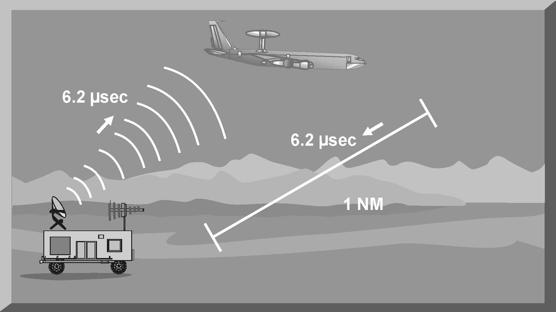
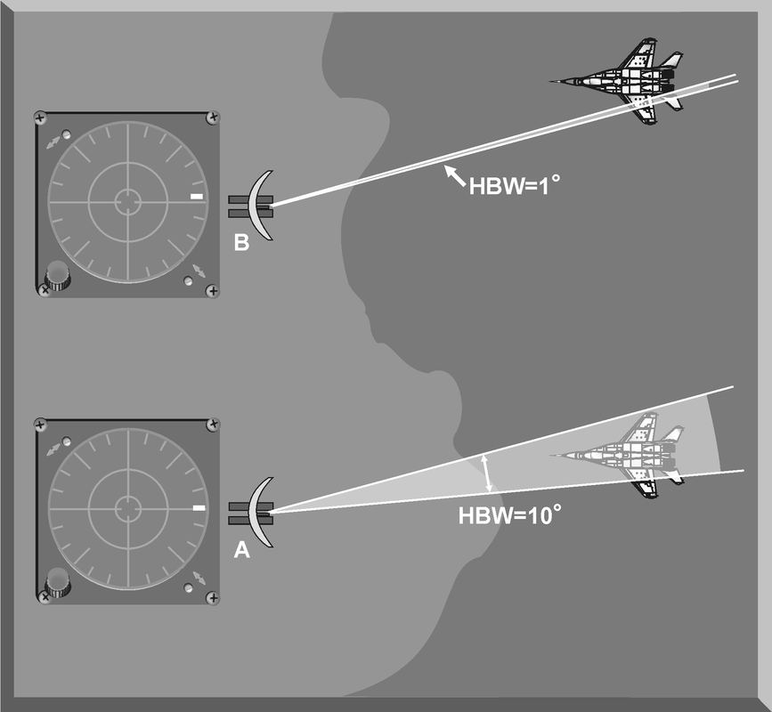
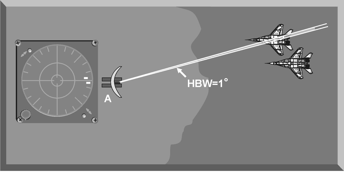
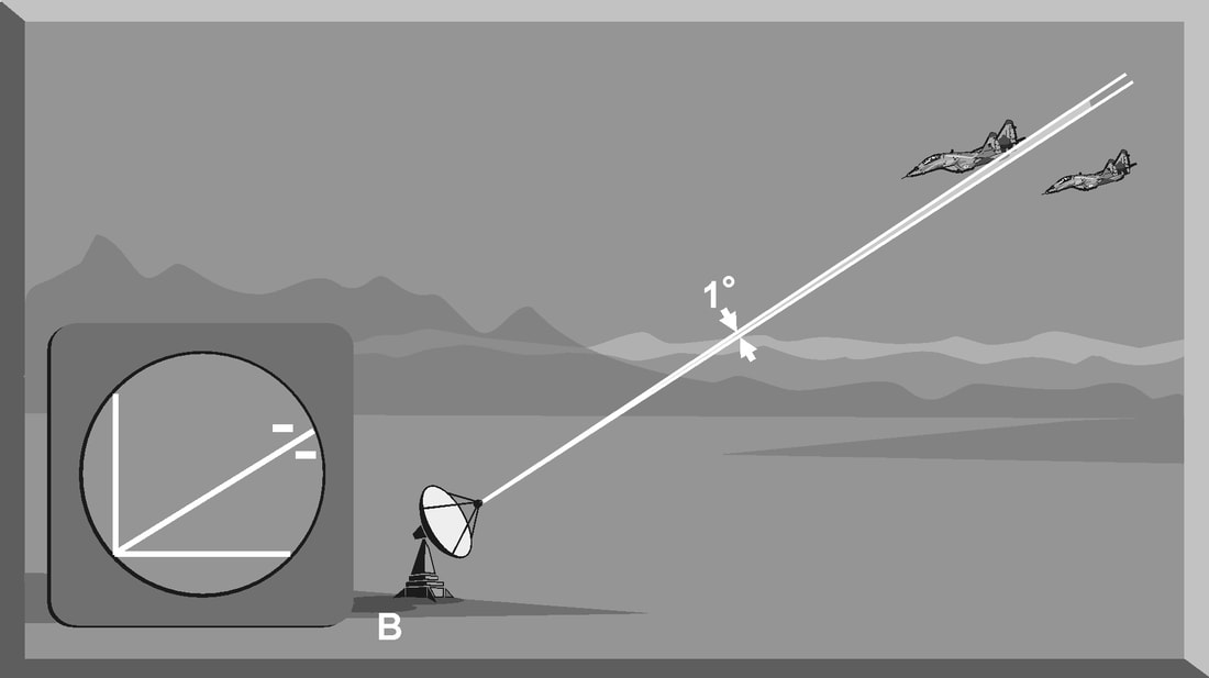
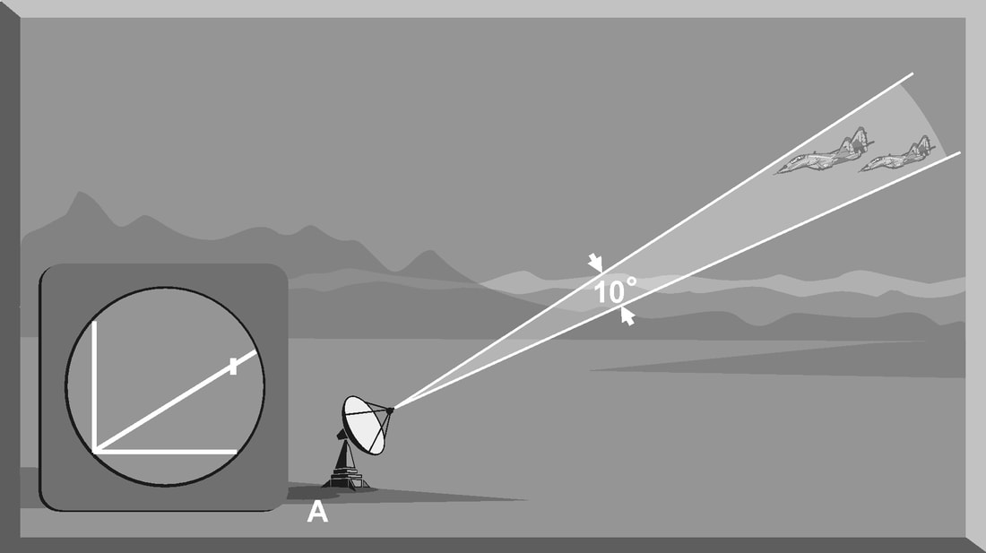
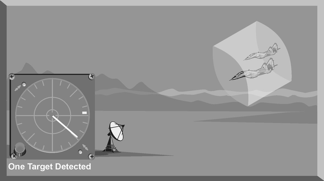
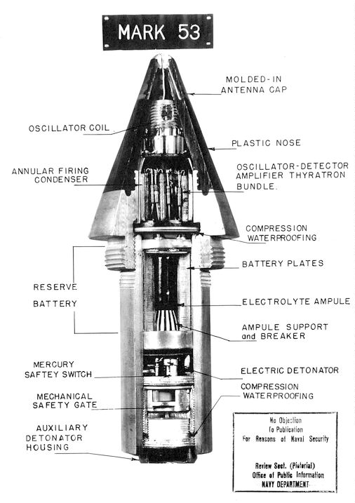
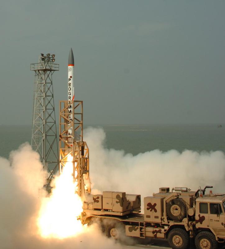
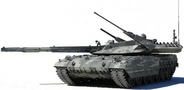
Introduction The primary purpose of radar systems is to determine the range, azimuth, elevation, or velocity of a target. The ability of a radar system to determine and resolve these important target parameters depends on the characteristics of the transmitted radar signal. This chapter explains the relationship of radar frequency (RF), pulse repetition frequency (PRF), pulse width (PW), and beam width to target detection and resolution. Radar range A basic pulse radar system consists of four fundamental elements: the transmitter, the receiver, the antenna, and the synchronizer, or master timer. Transmitter The transmitter, through the antenna, sends out a pulse of RF energy at a designated frequency. The presence of a target is revealed when the RF energy bounces off the target, returns to the radar antenna, and goes into the receiver. The master timer measures the time between the transmission of a pulse and the arrival of a target echo. RF energy travels at the speed of light (c) which is 3 x 10⁸ meters per second. Target range can be computed by using the basic radar range determination equation. Target Range = (measured Time * Speed of light)/2 Another useful measurement is the radar mile, which is the round trip time for an RF wave to travel to and from a target one nautical mile away. In simple terms the time required for a radar pulse to travel a distance of one nauticalmile and then return to the radar receiver. One radar nautical mile is equal to approximately 12.367 μs Measured time = (Target Range *2)/ c = (1853 meters *2) / 300000000 = 12.367 Micro Seconds. Radar timing is usually expressed in microseconds. To relate radar timing to distances traveled by radar energy, you should know that radiated energy from a radar set travels at approximately 984 feet per microsecond. With the knowledge that a nautical mile is approximately 6,080 feet, we can figure the approximate time required for radar energy to travel one nautical mile using the following calculation: A pulse-type radar set transmits a short burst of electromagnetic energy. Target range is determined by measuring elapsed time while the pulse travels to and returns from the target. Because two-way travel is involved, a total time of 12.36 microseconds per nautical mile will elapse between the start of the pulse from the antenna and its return to the antenna from a target. This 12.36 microsecond time interval is sometimes referred to as a RADAR MILE, RADAR NAUTICAL MILE, or NAUTICAL RADAR MILE 1 Radar Kilometer = 6.66 Micro Sec The range in kilometers to an object can be found by measuring the elapsed time during a round trip of a radar pulse and dividing this quantity by 6.66. The range in nautical miles to an object can be found by measuring the elapsed time during a round trip of a radar pulse and dividing this quantity by 12.36. A limitation on radar detection range is the concept of a second time around echo. A second time around echo occurs when a target echo associated with a particular radar pulse arrives at the antenna after another radar pulse has been transmitted. The radar master timer always assumes the target echo is associated with the last pulse transmitted. This makes the target echo ambiguous in range. Example: - Radar pulse A takes 372 microseconds to travel to the target and return. Using the range determination equation, actual target range is 30 nautical miles (nm). However, before the target echo returns to the antenna, radar pulse B is transmitted. The master timer associates the target echo of pulse A with radar pulse B, and calculates a target range of 10 nm. This ambiguous and false range is displayed to the operator. Modern radars are designed with second time around echo as important functional modes, and engineers have developed ways to resolve the ambiguity. Range resolution A critical aspect of range determination is range resolution. Range resolution is the ability of radar to separate two targets that are close together in range and are at approximately the same azimuth. The range resolution capability is determined by pulse width. Pulse width is the time that the radar is transmitting RF energy. Pulse width is measured in microseconds. A radar pulse in free space occupies a physical distance equal to the pulse width multiplied by the speed of light, which is about 984 feet per microsecond. If two targets are closer together than one-half of this physical distance, the radar cannot resolve the returns in range, and only one target will be displayed. The range resolution of the radar is usually expressed in feet and can be computed using Equation Range Resolution = (pulse width *984 ft)/2 It is the minimum separation required between two targets in order for the radar to display them separately on the radar scope. Azimuth Determination The beamwidth of a radar system is the horizontal and vertical thickness of the radar beam. Beamwidth depends on antenna design and is normally measured in degrees from the center of the beam to the point at which the power drops off by half. This half-power point is -3 dB in power drop-off. Beamwidth governs the azimuth and elevation accuracy and resolution capability of a radar system in the same way that pulse width governs radar range accuracy and resolution. In order for a radar system to figure out target azimuth, the antenna must be aligned with a point of reference and pointed at the target during the transmission and reception of several pulses of radar energy. If the antenna is referenced to true North, the azimuth of the target can be measured relative to true North. Azimuth determination is based on the position of the antenna when the target is being illuminated. To provide accurate azimuth determination over a large area, many types of radar employ a narrow beam and scan the antenna in a predictable pattern. The most common scan pattern is a 360° circular scan at a constant rate. The plan position indicator (PPI) radar scope display is normally associated with this scan pattern. As the radar beam sweeps, a target is detected and displayed. The position of the antenna, when the target is displayed, shows the relative azimuth. The azimuth accuracy of a radar system is determined by the horizontal beamwidth (HBW). Consider the following Figure, radar system A has a horizontal beamwidth of 10°. As the beam sweeps, the target is illuminated for as long as it is in the beam. This means that the target covers 10° in azimuth on the PPI scope. Radar system B has a beamwidth of 1°. A target displayed on the PPI scope will cover 1° in azimuth. The narrower the horizontal beamwidth, the better the azimuth accuracy. Azimuth resolution is the ability of radar to display two targets flying at approximately the same range with little angular separation, such as two fighters flying line-abreast tactical formation. The azimuth resolution capability is usually expressed in nautical miles and corresponds to the minimum azimuth separation required between two targets for separate display. Azimuth resolution depends on the horizontal beamwidth of the radar. The radar system in Figure has a horizontal beamwidth of 10°. The two targets are so cIose in azimuth that the return echoes are blended into one return. The radar system in the next Figure has a horizontal beamwidth of 1°. The radar beam not only hits the targets, but passes between them without causing a return. This allows the radars to display two distinct radar returns. A small horizontal beamwidth improves azimuth resolution. Azimuth resolution, in nautical miles, can be computed using Equation Azimuth resolution = (Horizontal Beam width * Range) 60 Notice that this equation is the “60 to 1 rule” used for navigation. A 1°beamwidth will yield a one-mile-wide cell at 60 nautical miles. Elevation determination Since a radar beam is three-dimensional, the vertical beamwidth is the primary factor in determining altitude resolution capability. Altitude resolution is the ability of radar to display two targets flying at approximately the same range and azimuth with little altitude separation, such as two fighters flying a vertical stack formation. The altitude resolution capability is usually expressed in feet and corresponds to the minimum altitude separation required between two targets for separate display. The radar system in Figure has a vertical beamwidth of 10°. The two targets are so close in altitude that the return echoes depicted on the range height indicator (RHI) are blended into one. The radar system depicted in Figure has a vertical beamwidth of 1°.This small beam not only hits the targets, but passes between them without causing a return. This allows the radar to display two distinct targets. Altitude/elevation resolution, in thousands of feet, can be computed using Altitude Resolution = (Vertical beam width * Range)/ 60 Radar resolution cell A radar's pulse width, horizontal beamwidth, and vertical beamwidth form a three dimensional resolution cell (RC) . A resolution cell is the smallest volume of airspace in which a radar cannot determine the presence of more than one target. The resolution cell of a radar is a measure of how well the radar can resolve targets in range, azimuth, and altitude. The horizontal and vertical dimensions of a resolution cell vary with range. The closer to the radar, the smaller the resolution cell. The physical dimensions of a radar's resolution cell can be computed. For a radar with a pulse width of 1 microsecond, a horizontal beamwidth of 1°, and a vertical beamwidth of 10°, the formulas for range resolution, azimuth resolution, and altitude resolution can be used to compute the dimensions of the resolution cell. For example , at a target range of 10 nm, the physical dimensions of the radar's resolution cell are 492 feet in range, by 1000 feet in azimuth, and 10,000 feet in altitude. These figures can be confirmed by using above Equations. Based on these computations, two, or more, aircraft flying a trail formation closer than 492 feet would be displayed as a single target. Two, or more, aircraft flying line abreast closer than 1000 feet would be displayed as a single target. Two, or more, aircraft flying a vertical stack closer than 10,000 feet would be displayed as a single target. This also shows that the shorter the pulse width, the better the range resolution capability of a radar system. The narrower the horizontal beamwidth, the better the azimuth resolution capability. The narrower the vertical beamwidth, the better the altitude resolution capability. Another type of resolution is velocity resolution. For a Doppler radar aircraft flying within the conventional resolution cell described above can be distinguished as separate targets if they have enough speed differentials. Pulse Doppler Velocity Determination To fully understand how a pulse Doppler radar determines target velocity, it is necessary to know more about the pulsed waveform. To generate a pulse modulated wave, a continuous carrier sine wave, like the output from a CW radar, is combined with a rectangular wave, like that of a pulse radar, to produce the pulse modulated waveform. Mathematically, any waveform other than a sine wave is composed of many different pure sine waves added in the proper amplitude and phase relationships. In a pulsed modulated waveform, the sine waves correspond to the fundamental frequency, which is the PRF, and the sum of all harmonics in the proper amplitude and phase. The frequency of the harmonic is the basic frequency plus or minus a multiple of the PRF. Below Figure is a plot of the harmonic content of a pulse modulated waveform operating at a carrier frequency of 2800 megahertz (MHz) with a PRF of 1 MHz. Note the loops of frequencies on either side of the carrier frequency. These are the additions and subtractions of all the frequencies in the rectangular pulse to the carrier frequency. The important thing to remember is that there are many frequencies present, and a pulse Doppler radar must deal with a crowded frequency spectrum. This becomes even more important when one considers the fact that every frequency present will experience a Doppler shift when it is reflected by a moving target. The individual frequencies shown are called spectral lines. For a pulse Doppler radar to accurately measure velocity, it must compare the frequency change, or Doppler shift, between the carrier frequency and the frequency returning from the target. It is a difficult task for the radar to differentiate between the returning carrier and all the harmonic frequencies. The radar differentiates between the returning carrier frequencies and all other harmonic frequencies by using clutter cancellers, or filters, at the known harmonic frequencies. The radar cannot process frequencies cancelled by these filters. The filters create “blind speeds” for the radar. The closer together the spectral lines, the more “blind speeds” the radar will have. Since the position of the harmonics in relation to the carrier frequency is based on PRF, the number of blind speeds can be reduced by changing the PRF of the radar. The higher the PRF, the wider the spacing of the spectral lines and the fewer blind speeds due to selective clutter canceling. However, a high PRF increases the problem of range ambiguities. Most modern pulse Doppler radars employ a medium and high PRF mode. Medium PRF equates to fewer range ambiguities but more blind speeds. High PRF has fewer blind speeds but more range ambiguities To separate the returning target frequency shifts from all other frequencies in the returning waveform, the pulse Doppler radar employs filters to cancel the known harmonic frequency shifts. In addition, the radar cancels out all returns with no frequency shift, which equates to canceling all returns with no movement relative to the radar. However, if the radar has too many clutter filters, this creates multiple blind speeds, and targets will be missed. Basic Radar Equation The basic radar equation relates the range of a radar system to the characteristics of the transmitter, receiver, antenna, and the target. The radar equation provides a means not only to figure out the maximum range of a particular radar system, but it can be used to understand the factors that affect radar operation. In this section, the simple forms of the radar equation are developed, starting with the power density of the transmitting antenna to the power received by the receiving antenna. Power density is the power of a radio wave per unit of area normal to the direction of propagation. The power density generated by a practical antenna can be expressed Power density from Antenna = (PT*G) / (4*pi*r2) PT = Transmitted Power G = Antenna Gain R = Radius of the antenna As the radar beam propagates through space, it arrives at a target at some range (R) from the antenna. As the radar beam travels through space, the wavefront of the beam expands to a very large cross-sectional area, especially in relation to the target dimensions. The power density of the radar beam, across this wide area, at the target, is detailed in the below Equation Power Density at Target = (PT*G) / (4*pi*r2) PT = Transmitted Power G = Antenna Gain R = Range to the Target Since the cross-sectional area of the radar beam is so large, only a small portion of the total power in the beam can be reflected toward the antenna. The rest of the radar energy continues through space and is dissipated, absorbed, or reflected by other targets. The small portion of the radar beam that hits the target is reradiated in various directions. The measure of the amount of incident power intercepted by the target and reradiated back in the direction of the antenna depends on the radar cross section (RCS) of the target. Equation details the power density of the target echo signal reflected back to the radar antenna is below Power Density at Antenna = [(PT*G) / (4*pi*r2)] * [RCS / (4*pi*r2)] PT = Transmitted Power G = Antenna Gain R = Range to the Target RCS= Radar Cross Section As the target echo reaches the antenna, part of the echo is captured by the antenna based on the effective aperture (Ae). Equation details the actual signal power received by the radar system follows. This is one form of the basic radar equation and is the signal strength of a radar return from a specific target at range (R) from the radar. Signal Power Density(S) = [(PT*G*RCS*Ae) / ((4*pi) 2*r4)] PT = Transmitted Power G = Antenna Gain R = Range to the Target RCS= Radar Cross Section Ae = Effective aperture A detailed analysis of this equation is not required to draw some basic conclusions about the factors affecting the detection of an aircraft. If any factor in the numerator, such as transmitted power, is increased by a factor of three, the signal received by the radar will increase by only 30 percent. This clearly shows why radar system operation is characterized by the transmission of megawatts of power and the reception of microwatts of returning power. In addition, this equation shows that the most critical factor in determining radar detection is target range. The maximum radar range (RMAX) occurs when the signal power density received just equals the minimum detectable signal (SMIN) for the receiver. Solving Equation for range, and substituting SMIN, yields the basic radar equation for RMAX for a specific target. This is another form of the basic radar equation. R max = [(PT*G*RCS*Ae) ¼] / ((4*pi) 2* S min)] PT = Transmitted Power G = Antenna Gain R = Range to the Target RCS= Radar Cross Section Ae = Effective aperture FUZES Every warhead must have a fuze. Fuzes are the devices which sense the right moment to detonate the warhead. There are numerous kinds of fuzes which operate on different principles and are suitable for different kinds of missiles, warhead and environment of operation. The most common types of fuzes are impact fuze, altitude fuze, and proximity fuze. Impact Fuzes Impact fuzes are used in all anti-tank missiles. Some anti-aircraft and anti-ship missiles also are provided with this fuze in addition to proximity fuze. In impact fuze, an electric pulse develops when it hits another solid object with a certain relative velocity which leads to high deceleration or inertia force. This electric pulse is used to trigger the warhead. The values of impact energy required for this purpose are always much above any impact that the missiles may be subjected to during normal handling and transportation operations. Altitude Fuze In this type the warhead detonation is initiated on sensing a preset altitude. This altitude sensing could be based on barometric pressure measurement or radio-altimeter reading. Proximity Fuze These are most often used when the impact possibility is less due to unavoidable errors in guidance and control, the missile is expected to pass in proximity if the target above or below, left or right within a certain distance. The proximity fuze can be active or passive system. In the active fuze a very low power and low range radar system transmits radiation only when the target is a small distance away and then when it receives certain strength of reflected signal it detonates. It can also be an active laser radar system. In a passive system it is generally infrared based proximity fuze. Launchers and Ground Support Systems All the missiles need certain ground systems to help launch them at the specific targets. Launchers are the most important of these systems. The large ballistic missiles are launched from silos under the ground or submarines or moblile vehicle based launchers. The small missiles are launched from a launch-cum-container tube resting on a human shoulder. The launchers can be very demanding piece of engineering effort with precision in aiming the launcher at a particular target and very high rates of turning in elevation and azimuth in case of' antiaircraft missiles. In addition, the ground support requires target search and tracking facilities which are normally provided by radar or optical sights, television or infrared detectors. If the missile range is say 50 km, the search radar will have range capabilities of as much as 100 km in good weather to give adequate time for launching the missile and intercepting the target at full range of missile. The ground system is developed to withstand the environment. For certain surface-to-air homing missiles the ground system will also help illuminate the target for the missile to home-in while command generation and transmission system is needed in command guided missiles. In addition to these we need communication and intelligence systems also on the ground to coordinate the functions of various missile launching units and have adequate information on targets. We also need to identify between enemy aircraft and friendly aircraft before launching a missile. This system is called IFF (Identification Friend or Foe). In this audio signal at known frequencies is beamed at the suspected target and if the signal is returned by the aircraft (it is automatic without pilot's participation) then it is friendly. In the case of long distance missiles extensive support in the form of ground computers and power supplies and air-conditioning, etc., are needed. Check out and Simulators To certify the missiles worthy of deployment and ready for operation, a periodic health monitoring of its vital subsystems is carried out. This is generally done through an automatic and computerized check procedure on the ground. Similarly, simulators are provided specifically for training the personnel in the operation of the missile. These simulate all the functions of the missile's electrical and microwave components. Test Ranges Extensive testing of missiles proceeds with their deployment. This testing is in two phases, i.e. development testing and user evaluation testing. These tests are done at test ranges which are suitably located keeping in view the safety requirements. The ranges have instrumentation facilities to collect data for evaluation of the missile flight. The safety zones of these regions a.re very much dependent upon the size and range of the missile and the flight path. Some of the ranges are located close to the sea while some others are located in the desert areas. In India the major range facility is located in Orissa at Balasore. There are two other test ranges equipped with instrumentation for testing launch vehicles, Thumba near Trivandrum and Sriharikota. These ranges are mainly for the use of Space Department. The instrumentation facilities provide for tracking radars, electro-optic instruments and telemetry receiving stations and meteorological facilities. In the range, flight tests are carried out from the Block House. Real-time data processing facilities and other facilities exist to ensure the range safety for carrying oat flight vehicles in case of using telemetry command system. This is the last article of our article series - Missile Technology Thanks for reading ................ 10) Mountain strike corps (XVII Corps) XVII Corps of Indian army is the first mountain strike corps of India which has been built as an quick reaction force and as well as counter offensive force against China along LAC . Its headquarters are located at Panagarh in West Bengal. India needs at least two Strike Corps to take the war into Chinese territory - one each for Ladakh and Arunachal Pradesh. On July 17, 2013, the Cabinet Committee on Security (CCS) approved the Army’s proposal for raising a Strike Corps for the mountains. Though the approval came after considerable delay, it was a pragmatic move that would send an appropriate message across the Himalayas. It will help India to upgrade its military strategy against China from dissuasion to meaningful deterrence as the Strike Corps, in conjunction with the Indian Air Force (IAF), will provide the capability to launch offensive operations across the Himalayas so as to take the next war into Chinese territory, while simultaneously defending Indian territory against Chinese aggression. It would break through Chinese defences, cross over into the Tibetan plateau and capture territory that would be a bargaining chip in a post-conflict settlement. Mountain Strike Corps will have strength of around 90,000 soldiers. The army was told to complete the raising of the mountain strike corps by financial year 2017-18. 9) BMD India achieved significant advancements in the direction of developing a two-layered Ballistic Missile Defence system. This enhances India's capability of dealing with a nuclear attack threat. Introduced in light of the ballistic missile threat from mainly Pakistan, it is a double-tiered system consisting of two land and sea-based interceptor missiles, namely the Prithvi Air Defence (PAD) missile for high altitude interception, and the Advanced Air Defence (AAD) Missile for lower altitude interception. The two-tiered shield should be able to intercept any incoming missile launched from 5,000 kilometres away. The system also includes an overlapping network of early warning and tracking radars, as well as command and control posts. Development of the anti-ballistic missile system began in 1999. Around 40 public and private companies were involved in the development of the systems. Defence Research and Development Laboratory (DRDL) developed the mission control software for the AAD missile. Research Centre, Imarat (RCI) developed navigation, electromechanical actuation systems and the active radar seeker. Advanced System Laboratory (ASL) provided the motors, jet vanes and structures for the AAD and PAD. High Energy Materials Research Laboratory (HEMRL) supplied the propellants for the missile. Two new anti ballistic missiles that can intercept IRBMs are being developed as part of Phase 2. These high speed missiles (AD-1 and AD-2) are being developed to intercept ballistic missiles with a range of around 5,000 km. The test trials of these two systems are expected to take place in 2011. The new missile will be similar to the Terminal High Altitude Area Defense missile deployed by the US. These missiles will travel at hypersonic speeds and will require radars with scan capability of over 1,500 km (930 mi) to successfully intercept the target. India is also planning to develop a laser based weapon system as part of its defence to intercept and destroy missiles soon after they are launched towards the country. DRDO's Air Defence Programme Director V K Saraswat says its ideal to destroy a ballistic missile carrying nuclear or conventional warheads in its boost phase. Saraswat further added that it will take another 10–15 years for the premier defence research institute to make it usable on the ground. 8) FMBT Defence Research and Development Organisation (DRDO) is working on India's future main battle tank (FMBT) with a 1,500-horsepower (HP) indigenous engine. This tank will replace beyond 2020 the imported T-72 tanks, renamed Ajeya, with the Army. Various specifications for the FMBT have been finalised. The country's military, which has projected a need for about 1,200 FMBTs. For engine development, formed a national team comprising members from the academia, the user, industry and the DRDO. The FMBT will weigh only 50 tonnes compared to Arjun-Mark II's 62 tonnes. The DRDO is simultaneously working on Arjun-Mark II. The volume occupied by the electronics package in the FMBT will be less. The FMBT's engine will be two-thirds the size of Arjun-Mark I's, but will generate 1,500 HP compared to Arjun-Mark I's 1,400 HP. Improvements in material, fuel injection and filtration technologies will contribute to the reduction in the engine size without compromising on power. Combat Vehicles Research and Development Establishment (CVRDE) are in the process of developing the FMBT with latest technologies. It is working in following areas:
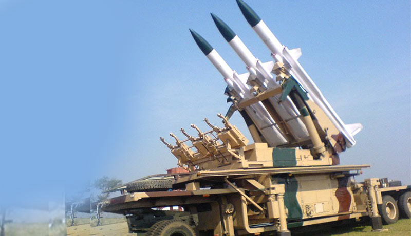
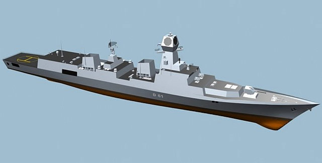
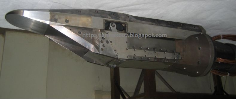
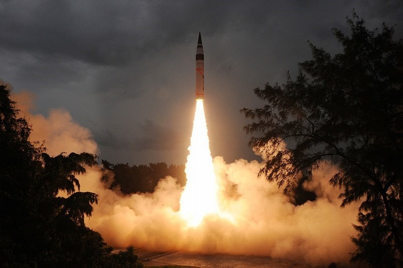
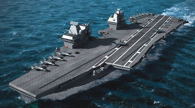
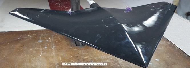
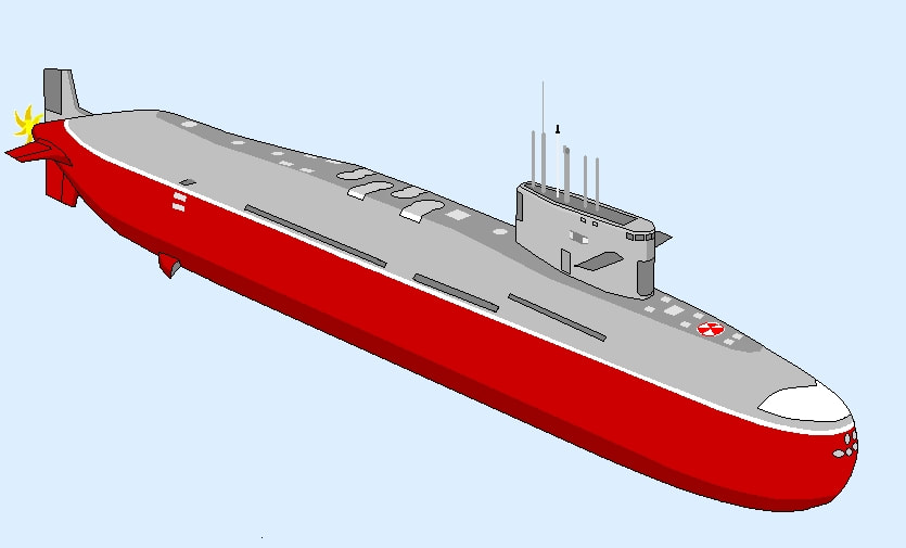
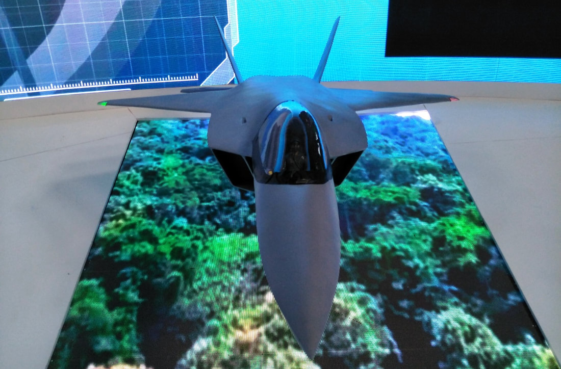
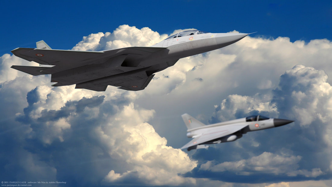
7) Vishakapattanam class and NGD Visakhapatnam class (Project 15B) is a class of stealth guided missile destroyers currently being built for the Indian Navy. Based on the Kolkata-class design, the Visakhapatnam class will be an extensively improved version. Ordered in 2011, the first ship is expected to be completed in 2018. Project 15B destroyers will feature enhanced stealth characteristics as well as incorporate state of the art weaponry and sensors. The first ship of Project—15B guided missile destroyer, christened Visakhapatnam. was launched on 20 April 2015 at a ceremony at Mazagaon Dock Limited (MDL), Mumbai. The Visakhapatnam is the first of four destroyers of the class designed by the Directorate of Naval Design in New Delhi. The stealth warship has a displacement of 7,300 tons and is 163 meters long. These ships will be propelled by four gas turbines in Combined Gas and Gas (COGAG) configuration and are capable of achieving speeds in excess of 30 knots [the warships can achieve a maximum speed of 31-32 knots] with a maximum endurance of 4000 nm. The Visakhapatnam-class vessels are designed to carry two multiple-role helicopters and are equipped with a vertical launching missile system capable of engaging shore- and sea-based targets from long range. The P15B destroyers incorporate new design concepts for improved survivability, sea keeping, stealth and ship maneuverability. State of art rail less helo traversing system is being introduced on these ships for efficient helicopter handling onboard. By increasing the cavitation inception speed the hydrodynamic noises and vibrations have been effectively reduced at the cruising speed in each of the ships of Project 15B. These ships can truly be classified as possessing a Network of Networks, as they are equipped with Integrated Platform Management System (IPMS), Ship Data Network (SDN), Automatic Power Management System (APMS) and Combat Management System (CMS). While control and monitoring of machinery and auxiliaries is achieved through the IPMS, power management is done using the APMS. The CMS performs threat evaluation and resource allocation based on the tactical picture compiled and ammunition available onboard. The SDN is the information highway on which data from all the sensors and weapons ride. Stealth has been a major thrust area in P15B design. Enhanced stealth features have been achieved through shaping of hull and use of radar transparent deck fittings which make these ships difficult to detect. The ship embodies features such as Multiple Fire Zones, Total Atmospheric Control System (TACS) for Air Conditioning, Battle Damage Control Systems (BDCS), Distributional Power Systems and Emergency DA to enhance survivability and reliability in emergent scenarios. These ships are also packed with an array of state of the art weapons and sensors, including vertically launched missile system for long distance engagement of shore and sea-based targets. The ship is one of the few warships of the world to be fitted with a Multi Function Surveillance Threat Alert Radar to provide target data to Long Range Surface to Air Missile system. The MF-STAR and LRSAM system is being supplied by M/s BEL. To protect against incoming airborne and surface threats at medium and close range, the ship has 76mm and 30mm gun mounts. NDG Indian Navy are now planning and conceptualising next generation destroyers which would be new in design and more potent. Next-generation destroyers will have additional features than the Project 15, Project 15 A and Project 15 B. NDG will be of 13000-tonne displacement warship with conventional propulsion and will feature next-generation weapons including laser weapons. 6) HSTDV & Brahmos2 HSTDV is an unmanned scramjet demonstration aircraft for hypersonic speed flight. The HSTDV program is run by the Indian Defence Research and Development Organisation. The Defense Research and Development Laboratory’s Hypersonic Technology Demonstrator Vehicle (HSTDV) is intended to attain autonomous scramjet flight for 20 sec., using a solid rocket launch booster. The research will also inform India’s interest in reusable launch vehicles. The eventual target is to reach Mach 6.5 at an altitude of 32.5 km. (20 mi.). India’s Defence Research and Development Organisation developed Hyper-sonic Technology Demonstrator Vehicle (HSTDV) unmanned scram-jet demonstration aircraft for hypersonic speed flight is all set for developmental flight by end of this year. Integration of all final flight hardware is happening right now and the team and is confident to conduct first hydrocarbon flight with scram-jet combustor by late this year thus joining an Elite group of countries in the world who have initiated their own scramjet engine research for hypersonic flight above Mach 5. HSTDV Cruise vehicle will be mounted on a solid rocket motor which is covered by fairings will take it to the required altitude and once required altitude and Mach numbers are achieved cruise vehicles will be ejected out of the launch vehicle and later Scramjet engine will be auto-ignited mid-air thus taking over to propel cruise vehicle for next 20 seconds at Mach 6. The aim of planned flight test of the project is to demonstrate autonomous flight of Hypersonic scramjet integrated vehicle using hydrocarbon fuel and also measure aerodynamics of the air vehicle, its thermal properties and scramjet engine performance. HSTDV will have a flight duration of 20 seconds at an altitude of 31 km which is also cruising altitude of Boeing 747 but at Mach 6. Scramjet combustor under development is of 520kg thrust engine which has cleared 4 static test for the 20-second duration at ground test facilities at simulated speed entry condition of Mach 2.25. Performance evaluation testing of scramjet combustor was carried out on the last leg off ground-based trials last year in June which was declared successful and scramjet combustor engine was cleared for the first flight. A supersonic missile is bad enough. But a hypersonic missile with a scramjet engine (where the through passing air is combusted at supersonic speeds unlike in ramjet engines where the air is slowed down to subsonic speeds before combustion) at Mach 20 plus is so indefensible you might as well give up the ghost. And its has tremendous range extension utility. For instance an Agni-5 with a hypersonic last stage will extend its range well beyond intercontinental distances. The Indian HSTDV-2 with a platypus nose, a titanium underside and aluminum-niodium topside, could be a strategic killer. Probably India be only the 3rd country which posses such an advanced weapon. There are rumors that India is backing of from the project because of pressure from certain Western quarters rattled by the prospect of India’s acquiring such a potent weapon. A test of the Hypersonic Technology Demonstrator Vehicle — HSTDV-2, scheduled at TsAGI (Central Thermal Hydrodynamics Institute) in the Moscow metropolitan region in December 2014 was abruptly cancelled. The rumour is Finance Ministry did not sanction the few crore rupees worth of funds required for trans-shipping the item, testing it in Moscow. Brahmos 2 Brahmos 2 is a hypersonic cruise missilecurrently under joint development by Russia's NPO Mashinostroeyenia and India's Defence Research and Development Organisation, which have together formed BrahMos Aerospace Private Limited. It is the second of the BrahMos series of cruise missiles. The BrahMos-II is expected to have a range of 290 kilometres and a speed of Mach 7.There is possibilities of extending the range because India joined MTCR recently. During the cruise stage of flight the missile will be propelled by a scramjet airbreathing jet engine. Other details, including production cost and physical dimensions of the missile, are yet to be published. It is expected to be ready for testing by 2020. Expert’s belives Brahmos 2 will be based on Russian Zicron Hypersonic Maneuvering Cruise missile. Russia is developing a special and secret fuel formula to enable the BrahMos-II to exceed Mach 5. 5) Agni 6 Agni-VI is an intercontinental ballistic missile being developed by the DRDO for the use of the Indian Armed Forces Strategic Forces Command. Agni-6 ICBM visualises a range of 6,000-7,500 km; a larger payload capability than the Agni-5 to carry multiple independently targetable re-entry vehicles (MIRVs); and even manoeuvrable re-entry vehicles (MARVs) to increase survivability against enemy anti-ballistic missile systems. The SLBM version of missile will arm the Arihant class submarines of the Indian Navy. DRDO revealed in 2012 that it is also in the process of developing another variant of Agni-VI missile. This will be a submarine-launched solid-fuel missile with a maximum range of 6,000 kilometres and a payload of three tonne 4) INS Vishal INS Vishal (IAC-II) is the follow-on class of Vikrant aircraft carrier currently in its design phase, which will be built by Cochin Shipyard Limited for the Indian Navy. It is intended to be the first supercarrier to be built in India. The proposed design of the second carrier-class will be a new design, featuring significant changes from INS Vikrant (IAC-I), including an increase in displacement. Vishal will displace 65,000 tonnes. It will be propelled by nuclear energy Navy already has finalised specifications of the second aircraft carrier which will include nuclear propulsion. Reactor technologies will come from India’s first nuclear submarine INS Arihant. Equipping INS Vishal with nuclear propulsions seems to be to gain greater operational endurance since warship powered by nuclear reactor means energy is unlimited and it can operate for over 20 years without refuelling The carrier will travel at 30 knots, a hair above the Vikrant, and come in at a length of 300 meters, longer than the 262 meter Vikrant. The Navy’s letter of request also outlines plans for the carrier to field between 30 and 35 fixed-wing combat aircraft and 20 rotary wing aircraft. The Navy’s letter of request states that that carrier will be the first in the Indian fleet—and first non-Western carrier—to field a catapult launched but arrest landing (CATOBAR) aircraft launch system. There is a possibility that the CATOBAR system could incorporate General Dynamics’ new electromagnetic aircraft launch system (EMALS) technology. Vishal will have integrated electric propulsion (IEP) or integrated full electric propulsion (IFEP) has been finally zeroed in to be integrated. IEP eliminates the mechanical connection between the engines and the propulsion which in turn reduces need for clutches and even Gear Box , Advantage of IEP for Surface ships has many advantages like reduction of weight and volume, Reduction in acoustic signatures, better placement of engines in the hull and reduced manpower for its maintenance . Indian Navy is looking to buy four carriers-based- airborne early warning and control aircraft for INS Vishal for which Northrop Grumman has provided Navy technical information on its E-2D Advanced Hawkeye which is only AEW platform which can operate from aircraft carriers. 3) Ghatak UCAV The classified effort to build a stealthy unmanned combat air vehicle formally received sanction as a ‘Lead-in Project’ last May, with the first funds released earlier this year. A project that has direct oversight from the Prime Minister’s Office and the National Security Advisor, Ghatak (which began as the DRDO’s Autonomous Unmanned Research Aircraft – AURA) has remained steadily out of view. Ghatak will be powered by a modified dry thrust version of the Kaveri engine (read on for more details of this modification), will sport a flying wing planform with internal weapons and will sport stealth characteristics developed wholly in-house. Let’s now get into what hasn’t ever been reported before about the Ghatak/AURA programme. While the Aeronautical Development Agency (ADA) is overseeing the programme along with the Gas Turbine Research Establishment (GTRE), the real R&D is being frontfooted by two academic institutions: IIT Bombay and IIT Kanpur. Since 2013, low speed experiemental studies have been carried out on the Ghatak’s serpentine intake by a team at IIT Bombay. This team has been made a kind of mini ‘Skunk Works’ towards proving computational fluid dynamics on the Ghatak, with no limits on resources and access to facilities. Two, two specialised research teams at IIT Kanpur were roped in in 2015 for wind tunnel testing of a low RCS intake (work began in mid-2016). The second was even more significant — in November 2015, a team from IIT Kanpur was brought on board to conduct and study the autonomous flight of a low RCS aircraft configuration with a ducted fan for multiple flight modes. Scientists shared the following image with Livefist, never seen before, that provides the first official schematic of the power/thrust configuration on the Ghatak. Over the last three-four years, the Aeronautical Development Agency has been made aware by several foreign airframers, including stealth pioneer Lockheed-Martin, Dassault, Boeing, BAE Systems,and even MiG Corp that they’d be willing to assist the Ghatak programme in a possible variety of ways — either as offsets, or a commercial consultancy arrangement. Livefist can however confirm that the Narendra Modi government has decided that the stealth component of the Ghatak programme will be entirely in-house, and will be limited to academic institutions and private industry in country. Scientists on the AURA/Ghatak programme confirm to Livefist that concept UCAV is tied in several ways to the fifth generation AMCA development , which itself could see technology infusions from a line-up of interested suitors, including Saab, Boeing and Dassault Aviation. The latter is keen to use its Rafale deal offset commitments to feed technologies into the Ghatak (and AMCA) programmes. The ‘Lead-in project’ sanction that the ADA obtained for the government was in fact a joint sanction for both programmes, given the huge number of common R&D elements, including shaping, materials, construction, intake geometry, data-links and avionics, weapons and of course the Kaveri engine. Top sources at ADA say that full project sanction for the modified Kaveri engine. 2) Arihant Class & Next Gen SSN The Arihant class is a class of nuclear-powered ballistic missile submarines being built for the Indian Navy. They were developed under the US$2.9 billion Advanced Technology Vessel (ATV) project to design and build nuclear-powered submarines. The lead vessel of the class, INS Arihant was launched in 2009 and after extensive sea trials, was confirmed to be commissioned in August 2016. A follow-on class of 6 SSBNs codenamed S5 is under development. INS Aridhaman is the second Arihant-class submarine. In August 2017, it was reported that she would be launched soon and would undergo outfitting. Harbor trials and sea trials are expected to last for 2 years and commissioning is expected sometime in 2019. Work on the third SSBN submarine is going on simultaneously but details are not available. Next Gen SSN Government cleared a project to build six new hunter killer boats (SSN) for the Navy. A joint Navy, BARC and DRDO project, the boats will be designed by Navy’s Directorate of Naval Design and be powered by a new reactor being developed by BARC. SSNs are as important as SSBNs as they can blockade important sea routes, denying the enemy access to important resources in an event of war, and shadow enemy ships. This new SSN will be similar in size to the Arihant-class but will carry advanced torpedoes and be able to move much quicker. 1) AMCA & FGFA AMCA Advanced Medium Combat Aircraft (AMCA) is an Indian programme to develop a 5+ generation fighter aircraft. More than four thousand staff devoted to the project, according to a report in 2015. ADA had settled upon a final design involving a twin-engine, canted twin-tail configuration, with an overall profile similar to that of the American F-22 Raptor. Mock-ups of this design have already reportedly undergone wind-tunnel and radar cross-section tests. ADA pitches the AMCA as one of the world’s top dogfight dukes, boasting “extended detection range and targeting, supersonic persistence and high speed weapon release”. Close-combat operations will be facilitated by “high angle of attack capability, low infrared signature and all round missile warning system. Four prototypes are expected in 2019”. That may sound overly optimistic – especially in the backdrop of stealth fighter programmes in the U.S., Russia and South Korea experiencing developmental issues. However, it is also a pointer to the Indian defence establishment’s confidence in its ability to develop an entire weapons platform from scratch after the success of the Tejas Light Combat Aircraft. According to Livefist the first 1:1 full scale model AMCA is being built in Bengaluru. Later this year, the model will undergo a series of rigorous tests at an RCS facility in Hyderabad, where the programme team will have its fest chance at seeing how the shape they’ve chosen for the jet deals with radiation. The exercise will be historic. Because it will be the first time India will be specifically testing a stealth airframe. FGFA Fifth Generation Fighter Aircraft (FGFA) or Perspective Multi-role Fighter (PMF) is a fifth-generation fighter being developed by India and Russia. It is a derivative project of the Russian Sukhoi Su-57 being developed for the Russian Air Force. India and Russia inked an inter-governmental pact for the FGFA project in 2007. Proposed development of FGFA based on Su-57 5th Generation fighter aircraft has been under negotiation for last 7 years and recently Indian Air Force submitted a favorable report on co-development of FGFA but it also pushed for far more Transfer of technology and deeper Indian involvement in the project. IAF is looking for Indian built FGFA to have nearly 70-80 % of components which can be sourced from India with Russian imports limited to less than 20-30 % range. IAF reportedly is also asking for better high thrust engines which have better serviceability and also have higher Indian made components. Apart from this there is many other ongoing as well as completed projects such as , Project 17 A, Rafale , Tejas MK2 , Pinaka MK2 ,NETRA AWACS & Next Generation AWACS , Rustom 2 , LCH, LUH, Akash SAM, Ka 226, AH 64 Apache , Chinook 47 , Nirbhay , Kalvari Class Submarines , DSAR, Midget Subs , Next Generation Missile Vessels etc etc Reference and Info sources IDRW.org National Interest Wikipedia Bharath karnad Global Security Tarmak007 |
AuthorPalash Choudhari Archives
June 2021
Categories
All
|
 RSS Feed
