|
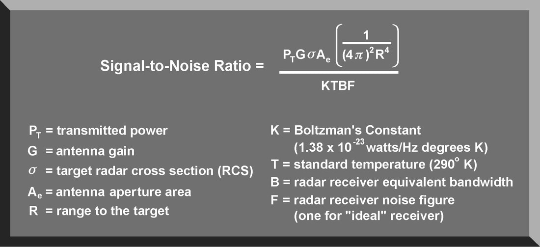
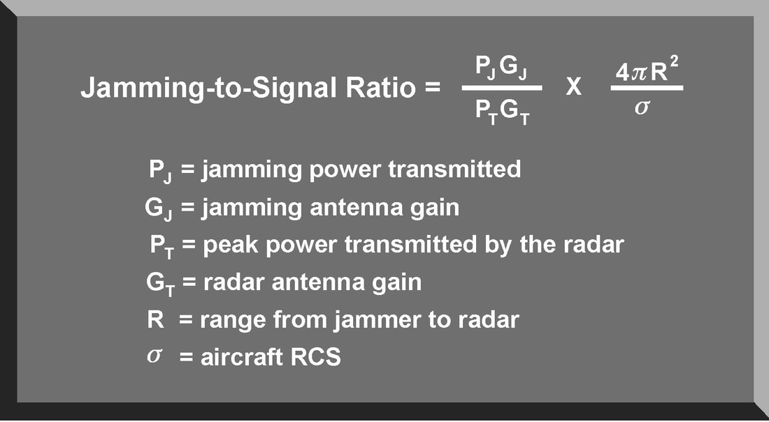
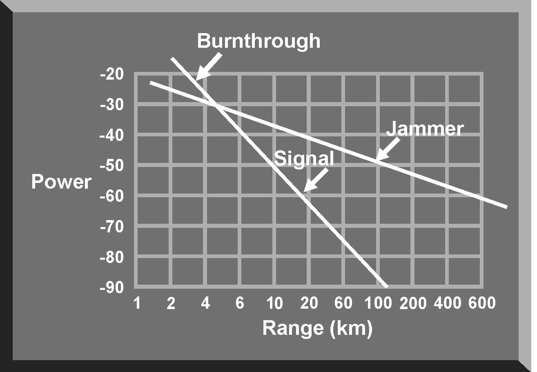
There are some fundamental principles that apply to all types of jamming and to all jamming employment options. These principles are based on the characteristics of the jamming system and the characteristics of the victim radar. They include frequency matching, continuous interference, signal-to-noise ratio, jamming-to-signal ratio, and burnthrough range. Based on the data provided by ES systems and intelligence evaluations, radar jamming systems must transmit signals at the frequency of the victim radar This applies to both noise and deception jamming. If a jamming signal does not match the transmitter frequency, the jamming signal is not received and displayed on the scope. When a jamming signal matches the transmitter frequency, the jamming signal is received and masks the target display . For maximum effectiveness, a jamming transmitter should produce continuous interference. In much the same way intermittent static on a radio receiver does not completely block out a signal, intermittent jamming on a radar scope may not completely mask the target. An experienced radar operator or advanced automatic tracker can “read through” intermittent jamming and derive sufficient target information to negate jamming effectiveness. While true for noise jamming techniques, continuous interference also applies to deception techniques, especially when target reacquisition is considered. Signal To Noise Ratio The signal-to-noise (S/N) ratio is a measure of the ability of the victim radar to detect targets. It is also an indication of the vulnerability of the radar to certain jamming techniques, especially noise jamming. The signal power density of the target return is so weak that it requires very strong amplification before processing and display. Besides the signal power from the target, some level of thermal noise is also generated and amplified along with the target signal. The radar receiver amplifies both target signal and thermal noise. The output of the radar receiver will contain the target signal and the noise amplified across the bandwidth of the receiver. Separating the desired target signal from the undesired noise signal is one of the major problems confronting radar designers. Target RCS fluctuates based on the changing angle of the antenna beam and corresponding changes in the reflected signal. Effective antenna aperture is also a statistical phenomenon based on the fluctuations in target RCS. The thermal noise generated by a receiver is also a fluctuating factor and must be treated statistically. This means that the S/N ratio is a statistical factor associated with a probability of target detection and a probability of a false alarm. A false alarm occurs when the radar operator or automatic tracking circuit designates a fluctuation in noise level as a target. The higher the S/N ratio, the higher the probability of target detection with a corresponding reduction in the probability of a false alarm. Any action that increases the power in the target signal (for example, increasing transmitted power, increasing antenna gain/aperture area, or decreasing target range) will improve the S/N ratio and improve the probability of target detection. It would also appear that decreasing the bandwidth of the radar receiver will increase the S/N ratio and enhance the probability of target detection. However, if the effective bandwidth of the receiver is reduced, this may eliminate a significant portion of the radar signal spectrum and decrease the probability of target detection. The S/N ratio is also an indication of the range at which a target will be detected. The weak target signal at an extended range is just above the receiver noise level. The target at closer range is easily detected above the noise level. A radar operator or automatic target detector could mistake the very weak target return as a fluctuation in the receiver noise level. This could result in a missed detection. The lack of discrimination between noise and target returns because of a poor S/N ratio can also result in designating fluctuations in the noise level as actual target signals, known as false alarms. To preclude, or minimize false alarms, the radar receiver may be equipped with electronic circuits to establish a false alarm threshold. If the signal strength of a radar return is below this threshold level, it will not be detected or displayed. This false alarm threshold also influences the probability of target detection. With the threshold set too high, many detected targets will not be displayed. Additionally, if the false alarm threshold is raised automatically in relation to the amplitude of the receiver noise, the radar receiver is more vulnerable to noise jamming. For any target return to be detected by the radar, the S/N ratio must be greater than one. If the S/N ratio is less than one, the target will not be detected above the receiver noise level. The purpose of noise jamming is to raise the level of noise in the radar receiver to reduce the S/N ratio to less than one. This masks the presence of the true target return. If a false alarm threshold is used, noise jamming raises this threshold to further complicate target detection Jamming-to-signal (J/S) ratio The jamming-to-signal (J/S) ratio is a fundamental measure of jamming effectiveness. The J/S ratio compares the power in the jamming signal with the power in the radar return. Equation 9-4 is an expression of the J/S ratio. It is important to note that the J/S ratio should be measured at the output of the radar receiver. This will allow consideration of the receiver signal processing gain applied to the jamming signal. The most critical factor in both the S/N and the J/S ratios is range. The S/N ratio is calculated based on R to the fourth power. This equates to a signal traveling from the radar to the target, and back to the radar receiver. The J/S ratio is calculated using R to the second power. This factor reflects the “one way” transmission of the jamming pulse from the jammer to the victim radar's receiver. For a jamming signal to be effective, the J/S ratio must be greater than one. In general, threat radars, especially ground-based radars, transmit much more power than does an airborne jamming system. However, this power must travel twice as far as the airborne jamming signal. At long ranges, a low power jamming system can generate a J/S ratio much greater than one. As the jamming system approaches the target, the distance the radar pulse travels decreases with a corresponding increase of power in the radar return. This reduces the J/S ratio to a value less than one and the radar “sees” the target. This is called the burnthrough range. Burnthrough Burnthrough occurs when the power in the reflected target signal exceeds the power in the jamming signal. Even when an optimum and continuous jamming technique is transmitting on the exact frequency of the victim radar, the jamming starts to lose effectiveness as it nears the radar. For a particular radar jamming technique, burnthrough range depends on the detection capability of the victim radar, expressed as the S/N ratio, and the capability of the aircraft's jamming system, expressed as the J/S ratio. The idea of burnthrough range explains why a jamming technique, especially noise jamming, loses its effectiveness as the aircraft approaches the radar. When plotting the jamming and signal power versus range , these two values intersect at the point where the J/S ratio is one. At closer ranges, the jamming pulse is no longer masking the aircraft, and the aircraft can be detected. Burnthrough range is the point where the radar can see through the jamming. SUMMARY
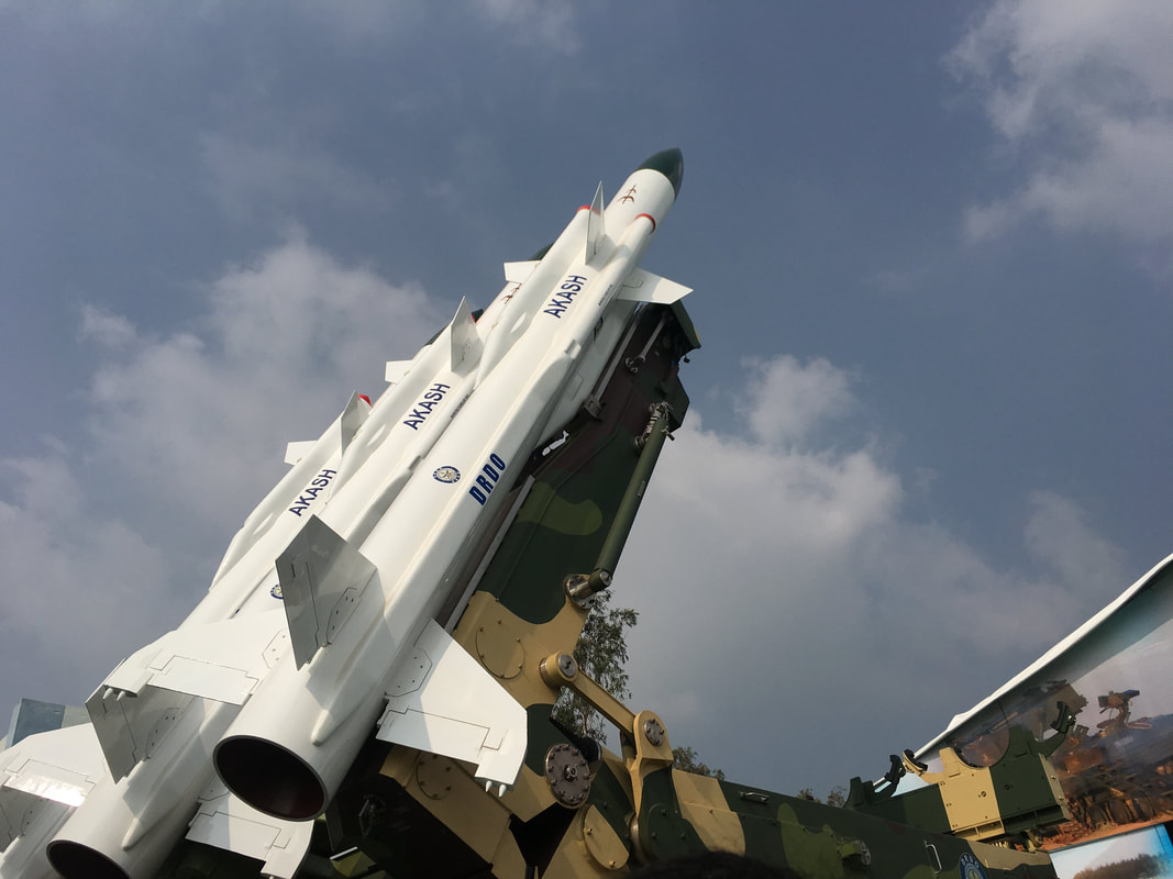
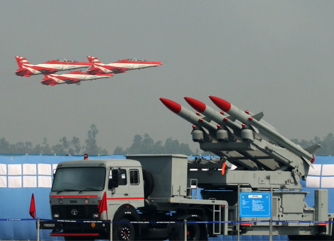
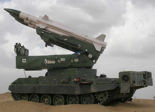
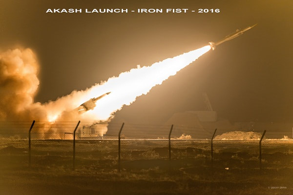
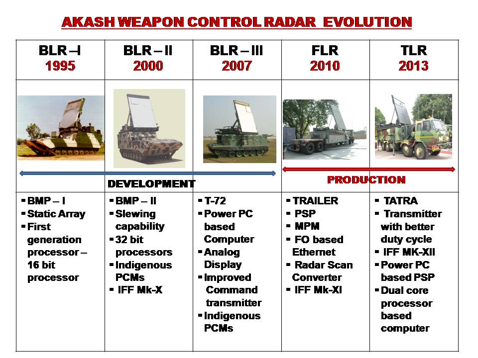
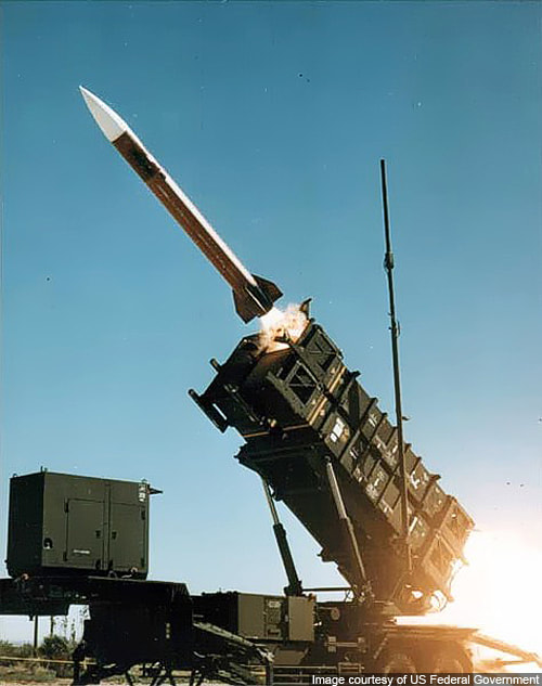
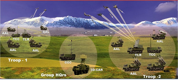
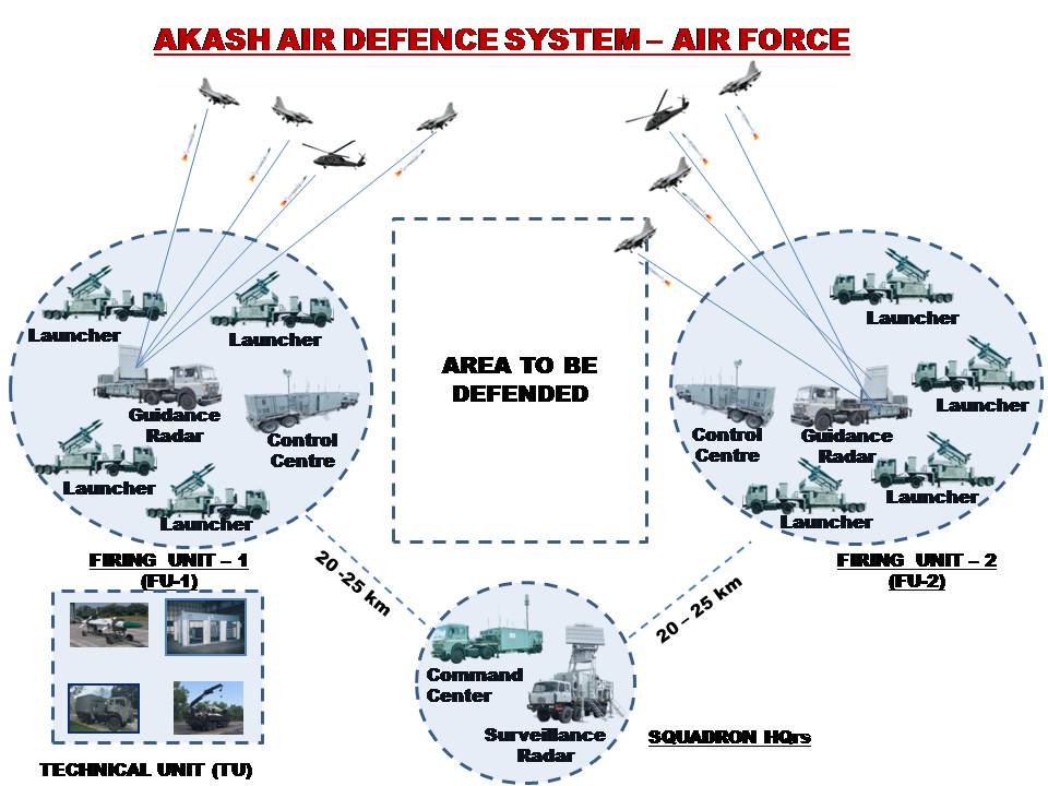
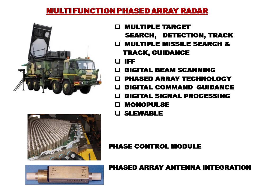
The purpose of radar jamming is to confuse or deny critical data to the radar systems that play a vital role in supporting the mission of an integrated air defense system. Two types of radar jamming, noise and deception, can be employed in a support-jamming role, or in a self-protection role for individual aircraft. The effectiveness of a jamming technique depends on the ability of the jamming system to generate a jamming signal that replicates the parameters of the victim radar, especially its frequency. The signal-to-noise ratio of the victim radar determines the vulnerability of the radar receiver to jamming while the jamming-to-signaI ratio is an indication of the ability of the jamming system to effectively jam the victim radar. These basic radar jamming concepts are fundamental to understanding the impact of specific jamming techniques on radar systems. Though late but Indians realised that nations must maintain a formidable military might to ensure peace in our terms. Tough times taught us the importance of indegeneous arms. By the start of the 1980s, the DRDL had developed competence and expertise in the fields of propulsion, navigation and manufacture of aerospace materials based on the Soviet Rockets. Thus, India's political leadership, which included PM Indira Gandhi, Defence Minister R Venkatraman, V.S. Arunachalam (Political Advisor to the Defence Minister), decided that all these technologies should be consolidated. This led to the birth of the Integrated Guided Missile Development Programme with Bharat Ratna Dr. A.P.J. Abdul Kalam, who had previously been the project director for the SLV- Program at ISRO, was inducted as the DRDL Director in 1983 to conceive and lead it. Initially many western nations formed groups like MTCR to deny advanced top notch technology to prevent India's rise. To counter the MTCR, the IGMDP team formed a consortium of DRDO laboratories, industries and academic institutions to build these sub-systems, components and materials. Though this slowed down the progress of the program, India successfully developed indigenously all the restricted components denied to it by the MTCR. Akash, the indigenous supersonic short-range surface-to-air missile (SAM) system, is one of the five missile projects of Integrated Guided Missile Development Programme (IGMDP) of the DRDO. The objective of the project Akash was to develop critical and sophisticated technologies for a ground system and a missile system and integrate these technologies into a state-of-the-art SAM air defence system capable of destroying multiple aerial targets simultaneously. Akash is a very potent supersonic mobile multi-directional multi-target point/area air defence system that can simultaneously engage several air threats like aircraft, helicopters and unmanned aerial vehicles up to a maximum range of 27 km up to an altitude of 18 km using sophisticated multifunction phased array and surveillance radars in a fully autonomous mode. Builtin ECCM features of Akash facilitate normal function in intense jamming environment. Three sets of combat elements of weapon systems like Battery Level Radars, Battery Control Centres and Self-propelled Launchers were made on BMP-I, BMP-II and T-72 chassis with modifications on hulls suitable to fit the equipment. All these systems were used in demonstrating the performance of the weapon system during development and user trials. A total of 38 vehicle-based systems were developed on both tracked and wheeled vehicles and were used to demonstrate the capability of the system through flight testing of 61 Akash missiles. IntroductionThe Akash SAM was developed to replace the Russian 2K12 Kub (SA-6 Gainful) missile system, currently in service. The Akash missile can be launched from static or mobile platforms, such as battle tanks, providing flexible deployment. The SAM can handle multitarget and destroy manoeuvring targets such as unmanned aerial vehicles (UAV), fighter aircraft, cruise missiles and missiles launched from helicopters. The Akash SAM system defends vulnerable areas in all weather conditions against medium-range air targets being attacked from low, medium and high altitudes. It can operate autonomously, and engage and neutralise different aerial targets simultaneously. The kill probability of the Akash is 88% for the first and 99% for the second missile on a target. The Akash SAM is claimed to be more economical and accurate than the MIM-104 Patriot, operated by several nations including the US, due to its solid-fuel technology. The Akash can intercept from a range of 30km and provide air defence missile coverage of 2,000km². The Akash SAM system consists of an integral ramjet propulsion, a switchable guidance antenna system, a command guidance unit, an onboard power supply, a system arming and detonation mechanism, digital autopilot, radars and C4I centres. The most important element of the Akash SAM system battery is its high-power, multi-function Rajendra phased-array radar. The 3D passive electronically scanned array Rajendra radar (PESA) can electronically scan and guide the missile towards targets. It provides information on the range, azimuth and height of a flying target. The Akash battery has four Rajendra radars and four launchers interlinked together and controlled by the group control centre (GCC). Each launcher, equipped with three missiles, is controlled by one radar that can track 16 targets. The Rajendra radar can therefore track 64 targets and simultaneously guide 12 Akash missiles. The PESA antenna array has a swivel of 360° on a rotating platform. The Rajendra radar can detect up to a radius of 80km and can engage at a range of 60km at an altitude of 8km. The communication links, command and control nodes, sensors and self-propelled launchers of the entire Akash SAM system are IT-integrated. The weapons system uses radar vehicles and T-72 tank chassis for launchers. The Akash missile has a launch weight of 720kg and measures 5.8m in length, 350mm diameter and 1,105mm wingspan. The missile can fly at a speed of up to Mach 2.5 and has a height ceiling of 18km. The 60kg payload can use prefabricated tungsten alloy cubes warheads or a nuclear warhead. The Akash uses state of the art integral ramjet rocket propulsion system to give a low-volume, low-weight (700 kg launch weight) missile configuration, and has a low reaction time - from detection to missile launch - of 15. It reaches a speed of Mach 1.5 in 4.5 seconds; Mach. 2.8-3.5 at 20g in 30 seconds after ramjet motor is ignited. Its range (for most effective performance) varies 27-30 kilometres. Unlike the Patriot, Akash can be launched from static or mobile platforms, including a battle tank. The missile can be deployed either in autonomous mode or group mode. In the autonomous mode, it will have a single battery functioning independently. For surveillance, it would need an additional two-dimensional radar. In this mode, it can be used for defending moving columns or singular installations. A single battery can simultaneously engage four targets, and against each target a maximum of three missiles can be fired, thus increasing the hit probability. In group mode, there would be a number of batteries, deployed over a wide area. The batteries would be linked to a group control centre (GCC). The Rajendra three-dimensional radar would provide a single integrated air picture to the group control centre, telling it not only the distance at which the enemy plane has been located but also its altitude. One GCC can command and control a maximum of eight Akash batteries at the same time. One GCC can also receive radar surveillance information from other sources, and be linked to higher echelons of air defence. Once the target, either an enemy aircraft or a missile, is detected the missile would align to the radar beams and virtually travel on those beams (guided by onboard precision-homing system) towards the target at three-and-a-half times the speed of sound. Its radars could be placed on a civil aircraft, much like an AWACS system, to provide early warning of incoming missiles. Radar SystemsThe missile is guided by a phased array fire control radar called 'Rajendra' which is termed as Battery Level Radar (BLR) with a tracking range of about 60 km. The tracking and missile guidance radar configuration consists of a slewable phased array antenna of more than 4000 elements, spectrally pure TWT transmitter, two stage superhetrodyne correlation receiver for three channels, high speed digital signal processor, real time management computer and a powerful radar data processor. It can track 64 targets in range, azimuth and height and guide eight missiles simultaneously in ripple fire mode towards four targets. The radar has advanced ECCM features. The Rajendra derivative on a BMP-2 chassis and to be used by the Indian Air Force is known as the Battery Level Radar-II whereas that for the Army, is based on a T-72 chassis and is known as the Battery Level Radar-III. The Army version also consists of the Battery Surveillance Radar (BSR). BSR is a track vehicle based, long range sensor, interfaced with the BCC. It can detect and track up to 40 targets in range and azimuth up to a range of 100 km. Long range target acquisition is performed by the 3D Central Acquisition Radar (3D CAR), which is a long range surveillance radar that can track up to 200 targets in Track while Scan mode (detecting, tracking and processing) in three dimensions at a range of 180 km. It provides azimuth, range and height coordinates of targets to the Group Control Centre (GCC) through secure communication links. The data is used to cue the weapon control radar. Rajendra Radar Rajendra is a slewable passive phased array radar used for 3-D target detection, multi target tracking and multiple missile guidance under extreme hostile EW environment. It makes use of a passive phased array to search a volume of space, distinguish between hostile and friendly targets, automatically track up to 64 targets and command one of several launchers to engage up to 4 targets simultaneously. Initially designed as a standalone system, Rajendra is now equipped with the ability to integrate with a network of sensors, including long and medium-range surveillance radars of foreign and indigenous origin. Rajendra's multi-element antenna arrangement folds flat when the vehicle is in motion. The Radar consists of a surveillance antenna array with 4000 phase control modules (PCM's) operating in the G/H-Band (4-8 GHz), engagement antenna array with 1000 PCM's operating in the I/J-Band (8-20 GHz), a 16-element IFF array and steering units. A powerful high-end computer computes phases for all the elements of the array. Rajendra controls the beam positioning sequence through beam requests for each track at adaptive data rates and performs multifunctional roles like search –confirm –track -interrogate targets, assign and lock on launchers, and launch/acquire/ track/guide missiles. The RDP supplies track data to remote group control centre. Rajendra features a Dual channel radar receiver and a C band transmitter, although the complete transmitting and receiving features and bands are unknown. Rajendra radar uses phase shifters integrated in large numbers for electronic beam steering. This allows Rajendra radar to simultaneously track multiple aircraft and also guide multiple missiles towards these targets. The phase shifter was designed and developed by Prof Bharati Bhat, a scientist from Centre for Applied Research in Electronics (CARE) of IIT, Delhi, and her team. The phased array radar rotates 360 degrees on a rotating turnstile at a moderate speed. This allows it to perform 360 degree surveillance. The phased array itself has 45 degree scan limits to either side, giving a total scan coverage of 90 degrees, if the radar array is static. During Multisensor Tracking a 2-D battery surveillance radar (BSR) with 360 degree coverage and a larger detection range provides track data to the multifunction, slewable, 3-D phased array radar. This is useful when a single battery of the Rajendra is detached from the group to fight alone, and early warning from the 3-D CAR is not available. The 2-D BSR data is then integrated by the Rajendra's radar vehicle. The multisensor direction finder in Rajendra processes the track data from the phased array radar and the BSR to identify the targets reported by both the sensors and maintains a common track database. For those BSR tracks, which are not being reported by Rajendra though under its coverage, target acquisition is initiated with elevation search in the designated direction. The antenna is skewed in the direction of threat to acquire the targets, which are outside the covered air space. The Rajendra's tracking range is 60 km against fighter aircraft flying at medium altitude. The major functions of the Rajendra are:
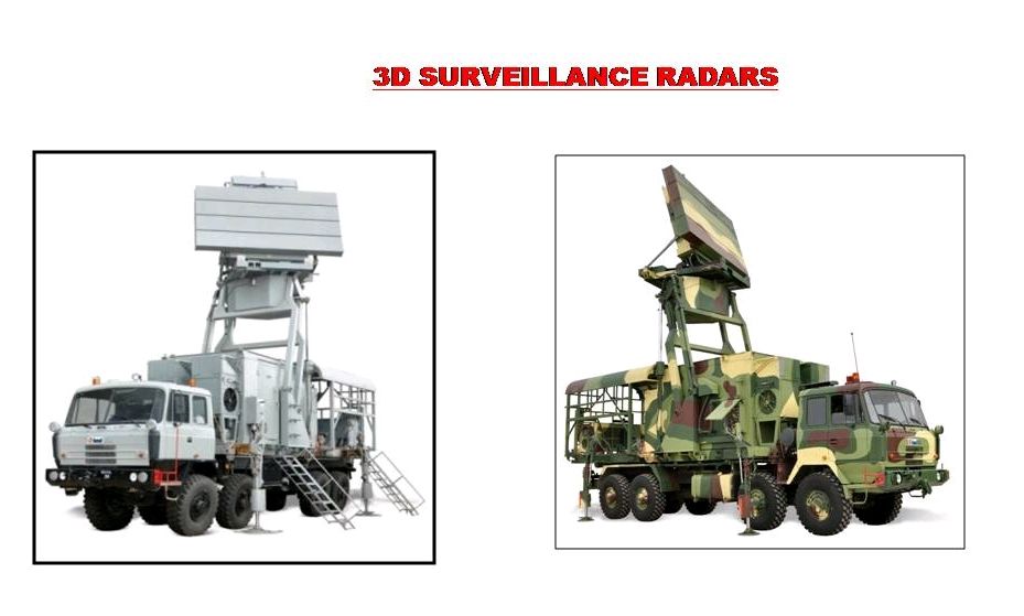
Central acquisition radar (3D-CAR) The central acquisition radar (3D-CAR) is a 3D radar developed by DRDO capable of tracking 150 targets. India has further developed its 3D CAR into all new ROHINI & REVATHI variants. The ROHINI is the Indian Air Force specific variant, whereas the REVATHI is for the Indian Navy. These replace the original joint development items such as the planar array antenna with new locally developed ones which are more capable than the original design. A third variant, known as the 3D Tactical Control Radar has been developed for the Indian Army and has cleared trials. Central acquisition radar (CAR) is a medium-range high-resolution 3D surveillance radar. Central acquisition radar was designed by LRDE, a DRDO laboratory, and is produced by a joint venture between BEL, Larsen & Toubro, Astra Microwave and Entec. The radar employs a planar array antenna and provides simultaneous multi-beam coverage. It can handle 150 targets in track while scan mode. Detonation The prefragmented warhead of the Akash missile is coupled with a digital proximity fuse. The detonation sequence is controlled by safety arming and a detonation mechanism. The missile is also integrated with a self-destructive device. Unlike the Patriot missile, Akash uses a ramjet propulsion system which gives it thrust to intercept the target at supersonic speed without any speed deceleration. The terminal guidance system of the missile enables its working through electronic countermeasures. The Rajendra radar completely guides the Akash missile, which increases its efficacy against electronic jamming of aircraft. The missile can carry a 60 kg warhead. The SYSTEM TRIALS Interception of moving aerial targets with Akash missile system was demonstrated through various flight tests in different mission profiles like: (a) Interception of far boundary targets (b) Near boundary targets (c) High altitude targets (d) Crossing and receding targets (e) Ripple mode firing on approaching and receding targets (f) Multiple target interception (g) Low altitude far boundary interception, and (h) Low altitude and near boundary interception. The system was also subjected to Electronic Warfare (EW) trials for proving the system resistance in intense jamming environment. Flight tests were conducted with deliverable production equipment of the Indian Army and IAF demonstrating target interceptions at low altitude near boundary UAV and precision guided bomb SPICE 2000 earning the satisfaction of the users. Salient Features
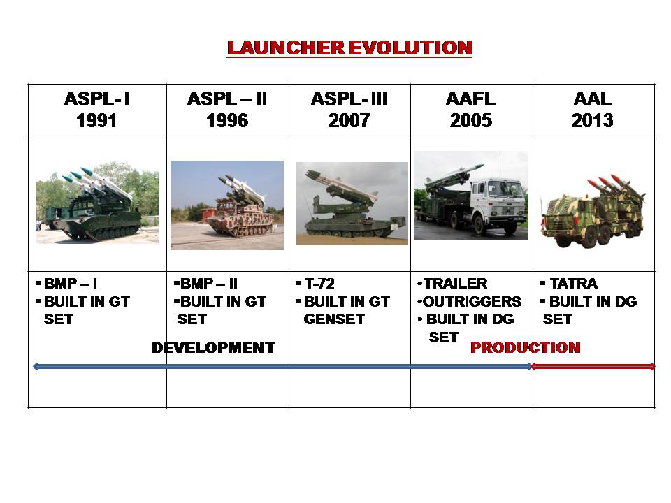
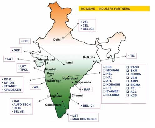
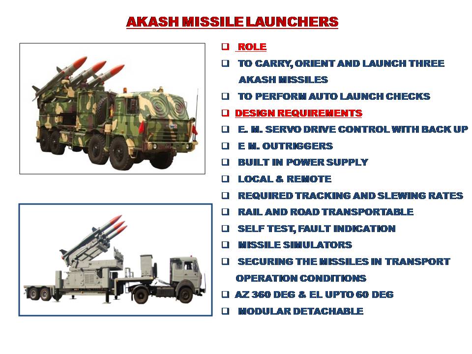
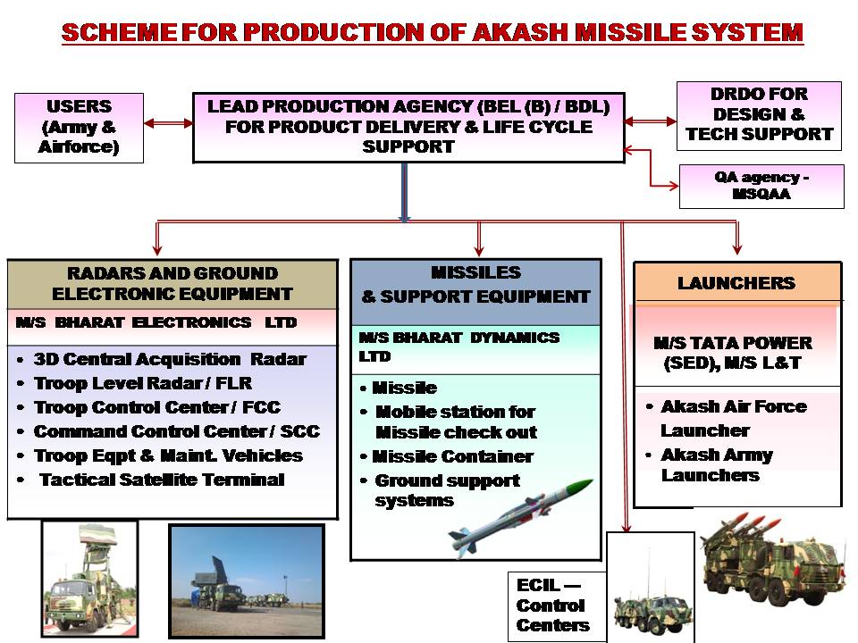
PARTNERS IN DEVELOPMENT Akash system is the outcome of successful partnership of Defence Research and Development Laboratory (DRDL), the nodal DRDO laboratory, along with 13 other DRDO laboratories; 19 Public Sector Units (PSUs) including Bharat Dynamics Limited (BDL), Bharat Electronics Limited (BEL), Hindustan Aeronautics Limited (HAL), Electronics Corporation of India Limited (ECIL), Heavy Vehicles Factory (HVF), Central Electronics Limited (CEL); major Private Industries like Tata Power SED, L&T; six Ordinance Factories, viz.,Itarsi, Khamaria, Bhandara, Medak, Chanda and Dehu Road; three national laboratories; six academic institutions, viz., IIT Delhi, IIT Madras, IIT Mumbai, IIT Kharagpur, IISc Bangalore and Jadavpur University; and more than 265 private sector industries across the country. Technological Breakthroughs Some of the indigenous technologies developed by DRDO during the programme are: integral ram rocket propulsion system, multifunction phased array radar system, multi beam 3D surveillance radar system, C4I system hardware and software for air defence application, command guidance system, dual control digital autopilot and PN guidance, digitally coded radio proximity fuze, electrical servo drive system, frequency hopping communication system, switchable guidance antenna system, built-in ECCM features for guidance, digital coded guidance schemes for multiple missile tracking, end game techniques for maximizing effectiveness of kill, multi-radar tracking and fusion of tracks, five-stage safety arming mechanism, dual frequency generating power supply system, digital signal processing techniques, software algorithms for automatic controlling of weapon system and simulators and training aids to demonstrate capability of system. PRODUCTION Based on the performance of system demonstrated through user evaluation trials, user field trials and flight tests, the system was formally inducted into Indian Army on 5 May 2015 and into the IAF on 10 July 2015. Production order worth Rs 20,000 crore was placed by the IAF and the Indian Army. Seeing the performance of Akash radars, Indian Armed Forces also placed orders for Akash offshoot products like Rohini, Revathi and the Weapon Locating Radars. Akash missile system is produced by nodal production agency Bharat Electronics Limited (BEL), Bengaluru for IAF and Bharat Dynamics Limited (BDL), Hyderabad, for Indian Army. Radars and radar-related equipment are being produced by BEL. While missiles and their related equipment are being produced by BDL, the launchers are being produced by Tata Power SED and M/s L&T. The control centres are produced by ECIL. About 300 MSMEs are involved in continuous production of components/ sub-systems/modules for Akash Missile System. The programme has ensured that the industry partners involved in development were also given preference for production. Additional industry partners were developed in some cases where the rate of production was required to be enhanced . During the production, DRDO revamped radars, control centres, launchers with re-engineering of system on trailers and high mobility (Tatra) vehicles as per the requirement indicated by the IAF and the Indian Army. Some performance enhancement features, which were demonstrated through flight testing, were added on deliverable production version equipment. Since, for the first time production of an indigenous SAM system of this magnitude was being attempted, DRDO guided all the stakeholders (DRDO labs, BEL, BDL, OFs, inspection agencies, industries and the users) towards successful production, inspection, testing, and validation. CURRENT Scenario Production of Akash missiles for Indian Army are being continuously monitored by the Project Group. Order worth Rs 5,500 crore for seven Squadrons (14 FUs) of Akash is expected by March 2018. Request for Proposal for two more Regiments of Akash Weapon System (with RF seeker missiles) worth about Rs 10,000 crore is also expected from the Indian Army. Eight (8/8) Squadrons of Akash missile system and six (6/12) Troops have been delivered to the IAF and the Indian Army, respectively. Infrastructure was created at user’s sites for storage, deployment, operation and maintenance of the system through lead production agencies. Supply chain or special surface-to-air weapon system elements like surveillance radars, missile guidance radars, launchers, control centres, missile subsystems, ground support systems, etc., have been established with stringent aerospace/military grade requirements. Realization of missile guidance radars (28/28), launchers (112/112), control centres (28/28), surveillance radars (22/22) has demonstrated DRDO’s commitment to the ‘Make in India’ initiative of the government. The DRDO created revenue of about Rs 38,000 crore through Akash missile system and its offshoot products, which is a commendable achievement for indigenous design and development. DRDO has also gained the experience of generating technology transfer documents for manufacturing, inspection, testing, and integration of the surface-to-air weapon system. DRDO also gained the experience of handling and guiding all the stakeholders at various critical stages of production, inspection, integration and acceptance. The Akash Missile System is today proudly safeguarding important defence assets of the country. Akash NG The development of the weapon system's next generation is currently underway. Main Material Source :- References DRDO WIKIPEDIA ARMY RECOGNITION Air force Technology |
AuthorPalash Choudhari Archives
June 2021
Categories
All
|
 RSS Feed
