|
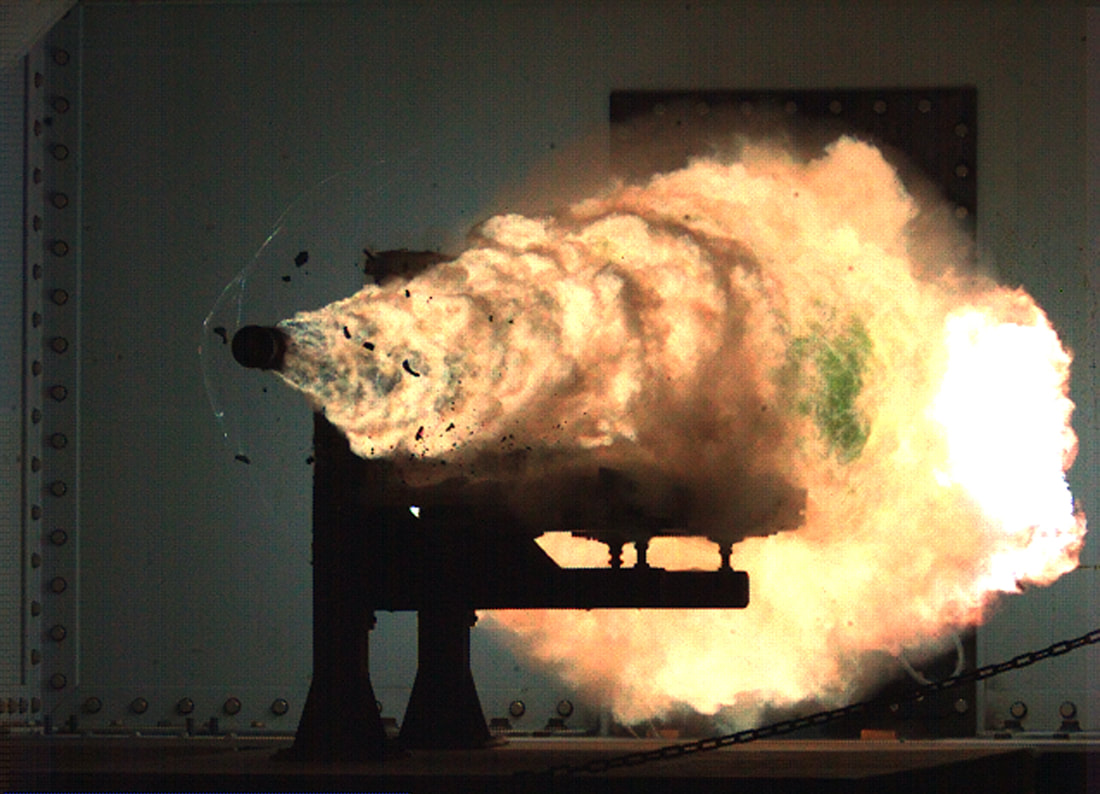
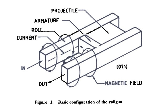
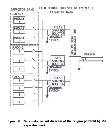
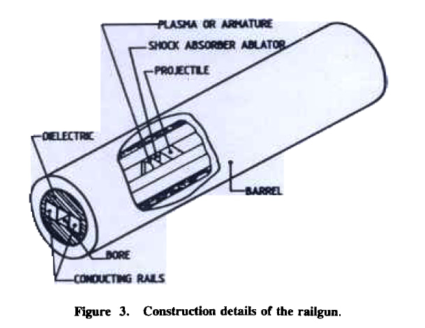
A railgun is a device that uses electromagnetic force to launch high velocity projectiles, by means of a sliding armature that is accelerated along a pair of conductive rails. US is the only country which developed a working rail-gun. Countries like India, China and Russia are researching to develop their own rail-guns. Below you can read a research paper published on Defense Science Journal in 1994. Even though it was an old article the basics are pretty much same. ABSTRACT A rail gun using electromagnetic propulsion was developed to launch hypervelocity projectiles. A 240 kJ, low inductance capacitor bank operating at 5 k V powered the rail gun. Launchers and projectiles were designed and developed for this purpose. The currents producing the launch forces are of the order of hundreds of kA. Even very low impedances for the current through the rail gun circuit are substantial sources of energy losses. A simulation code was developed to optimize the performance of the rail gun. Control and instrumentation facilities were set up along with a computer-based data acquisition system for measurement and analysis. The capacity to launch projectiles of 3-3.5 g weight to a velocity of more than 2.00 km/s was demonstrated. INTRODUCTION A facility was devel6ped to launch hypervelocity projectiles using electromagnetic energy. The projectiles were launched using a railgui1. The rail gun consists of two parallel rails and a conducting metalic foil placed behind the insulating projectile. When a high current flows through the rails, the foil explodes and forms a plasma armature. The force acting on the armature is given by Force at time t = 0.50 * Inductance per unit length of launcher * (current through the launcher at time t) 2 The rail gun currents are in the region of Hundreds of kA. This Lorentz force accelerates the projectile POWER SUPPLY An electromagnetic propulsion system requires a storage device with an energy density comparable to that of chemical explosives. The most expensive and technologically difficult part of the system is the high-energy electric source. The power sources considered for electromagnetic propulsion are well researched Capacitor Bank and Charging Unit The capacitor bank was used as a power source owing to its availability and lower cost despite its lower energy density. A low-inductance, 240 kJ capacitor bank was set up to provide the basic power to the railgun. A high-voltage charging unit was used to charge the capacitor bank. High Current Switches The capacitor energy is switched into the railgun by high-power ignitrons. When the peak current is reached, additional high-power ignitrons are used to crowbar the capacitors out of the circuit to obtain a dc pulse. This minimises the stress on the capacitors, the launcher and the projectile. Transmission Lines Low-inductance transmission lines were made using sandwiched conducting plates to maximize the energy transfer to the load. The transmission lines are subjected to repulsive forces owing to the passage of current through them. These, forces were 'estimated to provide proper bolting and bracing to avoid deformation of the transmission lines. LAUNCHER AND PROJECTILE Launchers and projectiles are subjected to high plasma pressures. High magnetic fields and high temperatures. In the present railgun set-up, the plasma pressures generated varied between 100 and 150 MPa. Launcher A simple, single pulse driven rail gun launcher was developed with a minimum of metal components in proximity to the bore to maximize the inductance of the launcher and to improve the launch efficiency. The launcher has a 12 mm square bore cross-section. The launcher was fabricated with lengths ranging from 1 to 2 m. The following launcher designs were used for the firings:
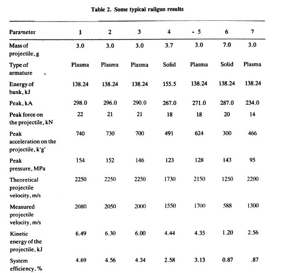
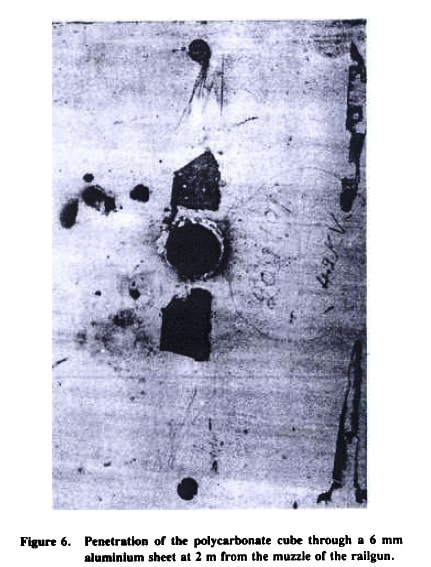
The launchers with the last two design modifications proved more reliable and durable than the launchers based on the first design. Thermal energy transfer from the rails leads to ablation and the melting of the bore materials. Such ablation degrades the performance of the railgun by adding parasitic mass to the plasma. The bore materials should have a high melting point and superior erosion and ablation resistance. High rail conductivity necessitated the use of copper rails. Polycarbonate and fiberglass were most suitable as bore materials. Loose bore to projectile tolerances or variation in bore dimensions can result in plasma leakage. Most of the launchers showed marked deterioration after a few shots. The deterioration could be attributed to changes in the bore dimensions due to the rail insulator ablation. Substantial deposits of carbon were observed inside the bore of the gun and needed cleaning. Projectile The projectiles are made of Perspex or polycarbonate cubes of 12 mm length. Perspex projectiles tended to shatter. Polycarbonate projectiles survived the high plasma pressures. The plasma and the solid armature were both used for carrying the high currents. Most firings were carried out using plasma armature. A plasma armature is formed when Al/Cu foil melts/explodes on the passage of high currents. The foil vaporizes by joule heating to produce plasma to drive the armature. A neoprene obturator was placed at the rear of the projectile to seal the bore against plasma leakage around the projectile. As a deviation, a solid metallic projectile acting as an armature was also used to carry the current. DATA ACQUISITION AND SIMULATION Data Acquisition A computer-based data acquisition system was set up to monitor important parameters that affect the performance of the railgun. Current transformers and Rogowski coils were used to measure the rail currents in the range6 of 100 to 500 kA. Magnetic probes were used to get the position-time profile of the projectile inside the bore of the gun and railgun current distribution. These probes help detect plasma leakage and formation of secondary arc. The velocity outside the bore of the gun was measured using shorting screens. A high-speed camera was set up to measure the velocity of the projectile and establish the integrity of the projectile at the muzzle end. This is a non-contact method and is free from electromagnetic pickups. Simulation A simulation code was developed to predict the performance of the railgun. The performance of the model was evaluated by monitoring different parameters ANALYSIS All measurements were supported by appropriate software developed to analyse the entire performance of the railgun. The current-time data are used to predict the displacement, velocity and acceleration of the projectile and the plasma pressure. RESULTS Some typical railgun trial results are given in Table. Projectile velocities greater than 2000 m/s were obtained for trial no’s 1 to 3. The efficiency varied between 4 to 5 per cent with railgun current in excess of 260 kA. Plasma leakage and formation of secondary arcs were responsible for the lower projectile velocities than expected from the computer model for trial no’s 5 to 7. Trial no.7 was done using a solid conducting projectile made of aluminium. An armature was kept behind the projectile with no ablator. The armature vaporized and the plasma escaped ahead of the projectile. This led to a lower system efficiency and projectile velocity. A solid projectile made of Perspex and armatures made of several copper foils were used in trial no.4. The mass of each foil was kept around 100 mg to avoid the melting of the armature owing to the high railgun current. CONCLUSION Our study has shown that projectiles attain hypervelocity’s by using a single small square bore railgun. In the existing railgun facility the efficiency varied between 4 to 5 per cent. Significant improvement in the efficiency of the railgun set-up is one of the key issues that will determine the use of railguns for various weapon applications. Hence we carried out detailed modelling and simulation of the entire railgun system. The results from the simulation were validated with the measurements. Measurements made at high common mode voltages of around 1000s of volts and high electromagnetic noise were exceptionally good, providing reliable and repeatable records. Intact projectile launch and 2-3 m of free flight projectile were studied using high-speed photography when punctures in the shorting screens were observed. Using a high-speed camera the integrity of the projectile was established beyond doubt. A 12 mm cubical polycarbonate projectile weighing about 3 g could defeat a 6 mm aluminium sheet at 2 m from the muzzle end of the gun). The complete railgun system was also placed in a 5 m long vacuum chamber to study the railgun performance. Our studies are as yet inconclusive. Owing to the failure of some odd capacitors in the capacitor bank, repetitive trials could not be carried using the full energy of the bank. The energy extracted from the capacitor bank varied between 120 and 160 kJ. The kinetic energy of the projectiles can be increased substantially by using a higher-energy capacitor bank as a power source
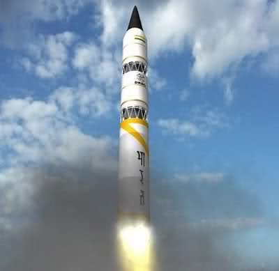
Due to unknown reasons Rail-gun development was not completed at that time. But from this press release of Ministry of Defense, it is clear that DRDO restarted their work in the field of Electromagnetic rail gun along with other futuristic technologies like Supersonic Missile Assisted Release of Torpedo, Stealth Wing Flying Test bed, AESA Based Integrated Sensor Suite, Multi-Agent Robotics System etc http://pib.nic.in/newsite/mbErel.aspx?relid=158187 Info Source Defense Science Journal, Val 44, No 3, July 1994, pp 257-262 S.G. Tatake, K.J. Daniel, K.R. Rao, A.A. Ghosh, and I.I. Khan Armament research & Development Establishment Pune-410121 Agni-VI is an intercontinental ballistic missile under development by the DRDO for the use of the Indian Armed Forces. Agni-VI will be a four-stage intercontinental ballistic missile. Agni-6 will carry a massive three-tonne warhead, thrice the weight of the one-tonne warhead that Agni missiles have carried so far. This will allow each Agni-6 missile to launch several nuclear warheads -Multiple Independently Targetable Re-entry Warheads (MIRVs) - with each warhead striking a different target. Each warhead - called Maneuverable Reentry Vehicle (MARV) - performs evasive maneuvers while hurtling down towards its target, confusing enemy air defence missiles that are trying to destroy them mid-air. And these maneuverable warheads will give Agni VI an extended range exact figure of which is currently classified. It will be taller than its predecessor Agni V, and is expected to be flight tested by 2017. Agni-VI missile is likely to carry up to 10 MIRV warheads and will have a strike range of 8,000 km to 12,000 km.
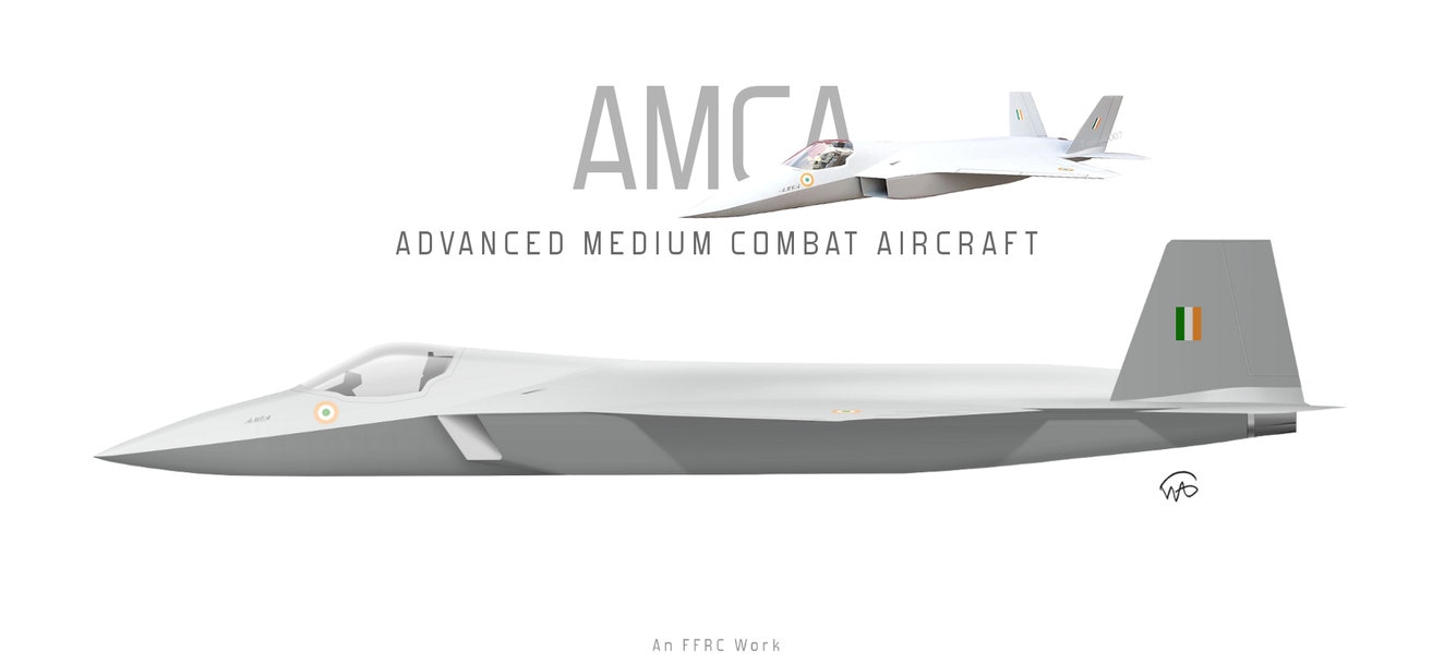
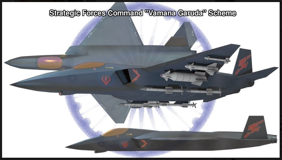
Guidance system of Agni 6 will include inertial navigation system with Ring laser gyroscope, optionally augmented by IRNSS. Terminal guidance with possible radar scene correlation (this is a kind of terrain contour mapping this improves the accuracy of missiles). AMCA or the Advanced Medium Combat Aircraft is a fifth-generation fighter aircraft which will be manufactured by HAL. The AMCA programme is envisaged as replacement for a host of aircraft currently operated by the IAF as well as to fill gaps left by retirement of the Dassault Mirage 2000s, SEPECAT Jaguars and Mig-27s.ADA describes the AMCA as a "multirole combat aircraft for air superiority, point air defense, deep penetration/strike, special missions".
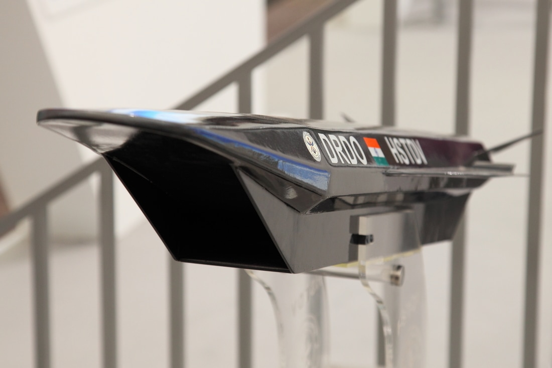
Unofficial design work on the AMCA started in 2008 with official work started in 2011 and completed in 2014. In 2008 Indian Navy also showed interest in the naval variant of AMCA. All the design work is completed and ADA is waiting for the approval of Indian government to develop the first prototype. The broad requirements outlined for the AMCA are to incorporate a high degree of stealth, a high internal and external weapons payload, high internal fuel capacity, and the ability to swing from an air-to-air role to air-to-ground. It is also expected to have the ability to super cruise. This allows the aircraft to travel at supersonic speeds with greater endurance as the afterburners do not have to be used with the additional fuel usage. Even though future air combat has been envisaged as being beyond visual range excluding the likelihood of aerial dogfights as before, the AMCA is expected to sport a thrust vectoring engine. The ADA is designed the AMCA as a platform with high survivability, to meet the challenges of future air defense environments through a combination of moderate stealth, electronic warfare capability, sensors and kinetic performance. The design philosophy seeks to balance aerodynamics and stealth capabilities. The aircraft will have a weight of 16-18 tons. 16-18 tons with 2-tons of internal weapons and 4-tons of internal fuel. Combat ceiling will be 15-km, max speed of 1.8-Mach at 11-km. The AMCA will be powered by 2 x 90KN engines with vectored nozzles. The HSTDV is an unmanned scramjet demonstration aircraft for hypersonic speed flight. The HSTDV program is run by DRDO.HSTDV is awaiting a crucial test . A 20-22 second test of the HSTDV would be crucial for the hypersonic missile program. The design for airframe attachment with the engine was completed in the year 2004. We have eclusive images of that testframe.
|
AuthorPalash Choudhari Archives
June 2021
Categories
All
|
 RSS Feed
