|
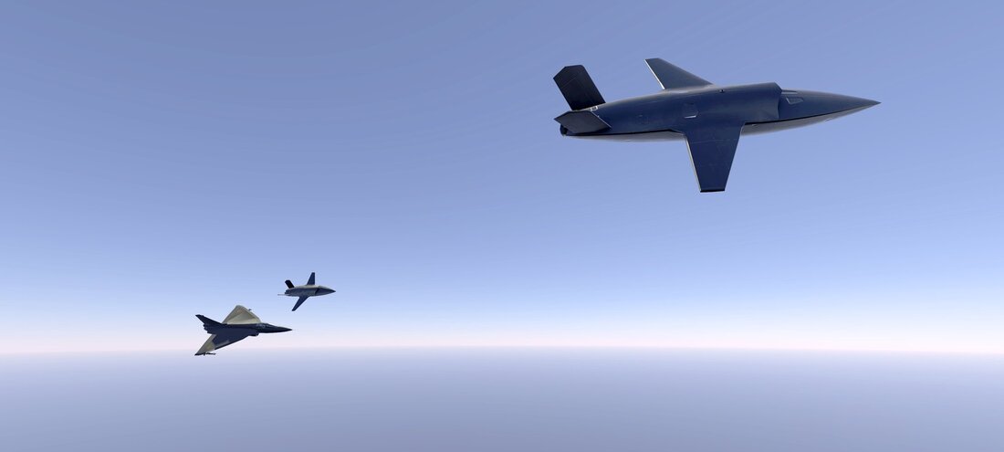
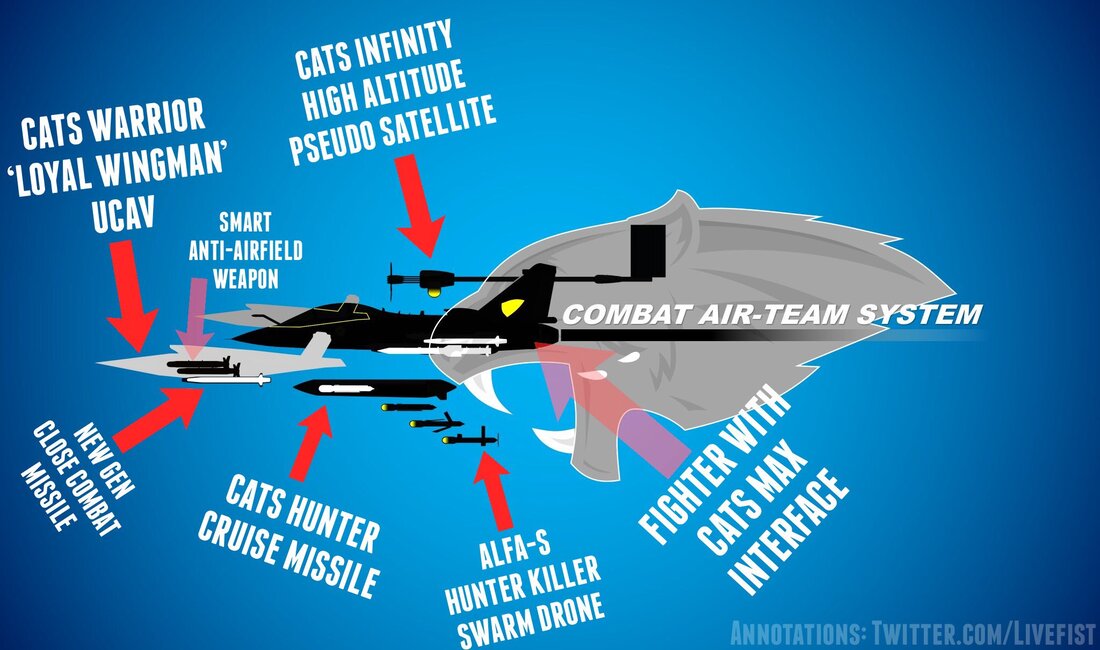
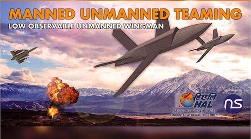
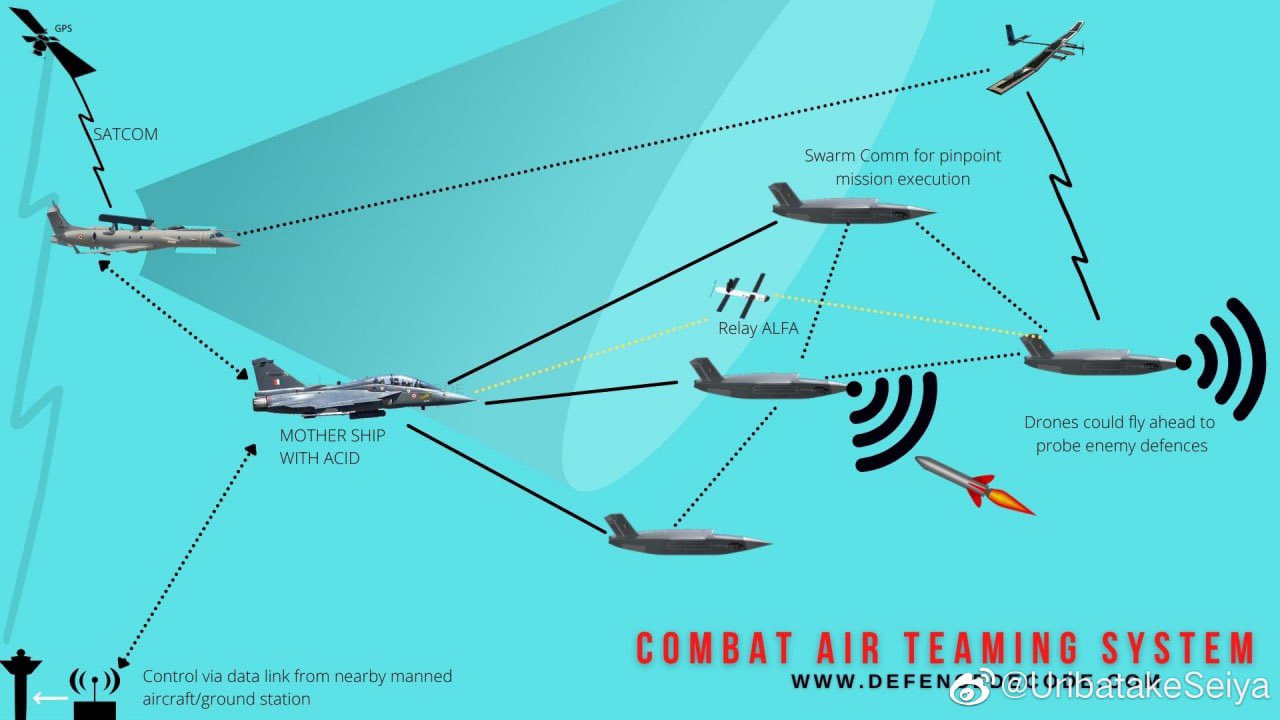
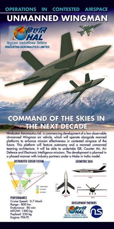
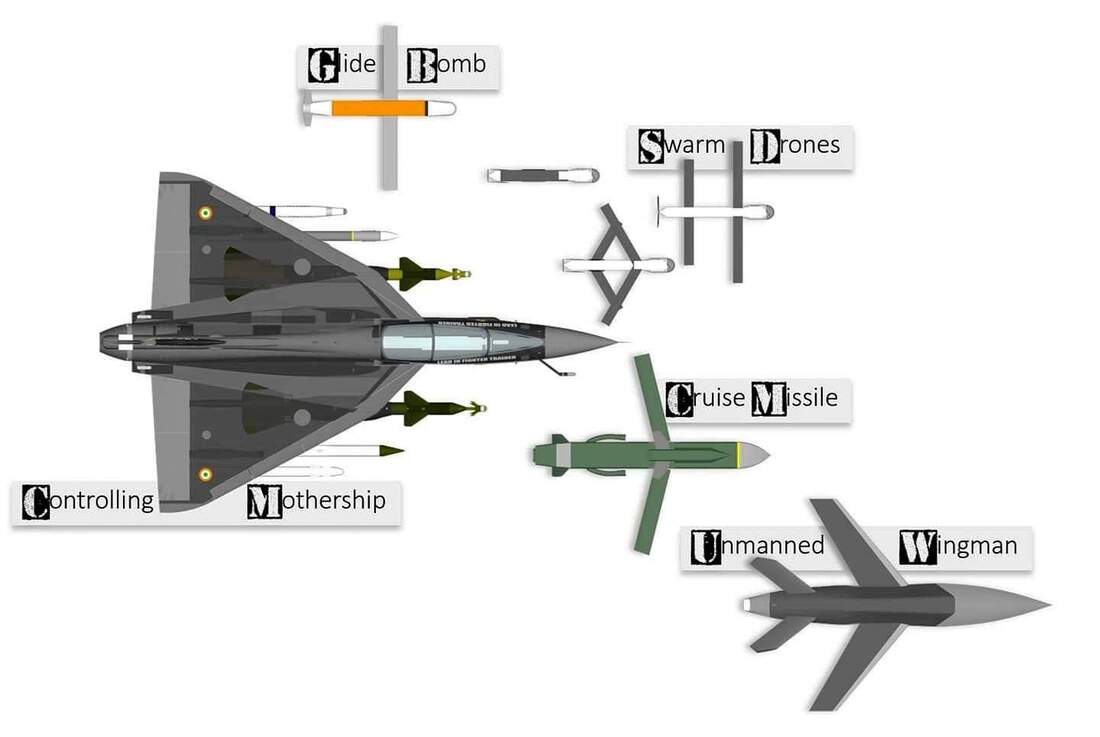
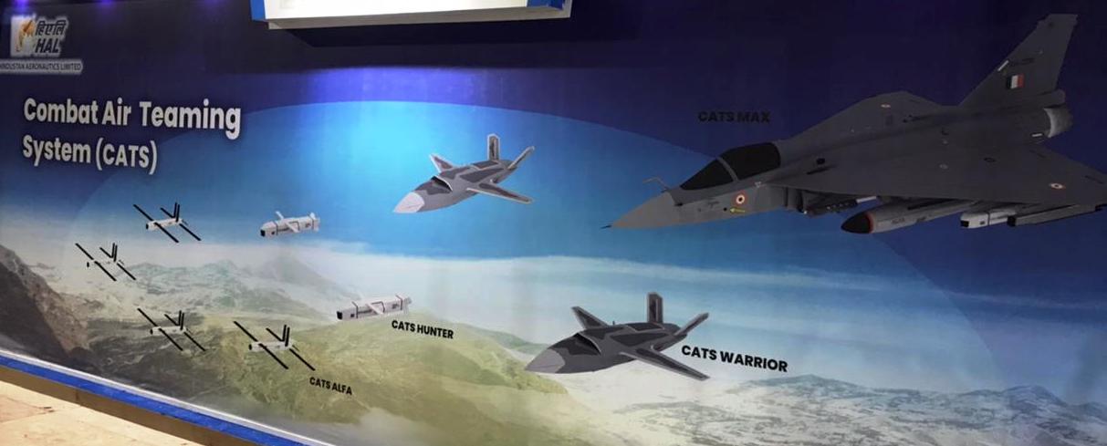
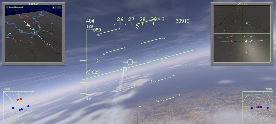
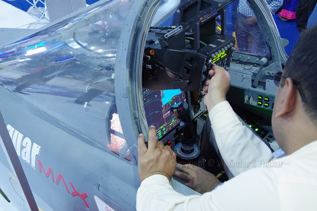
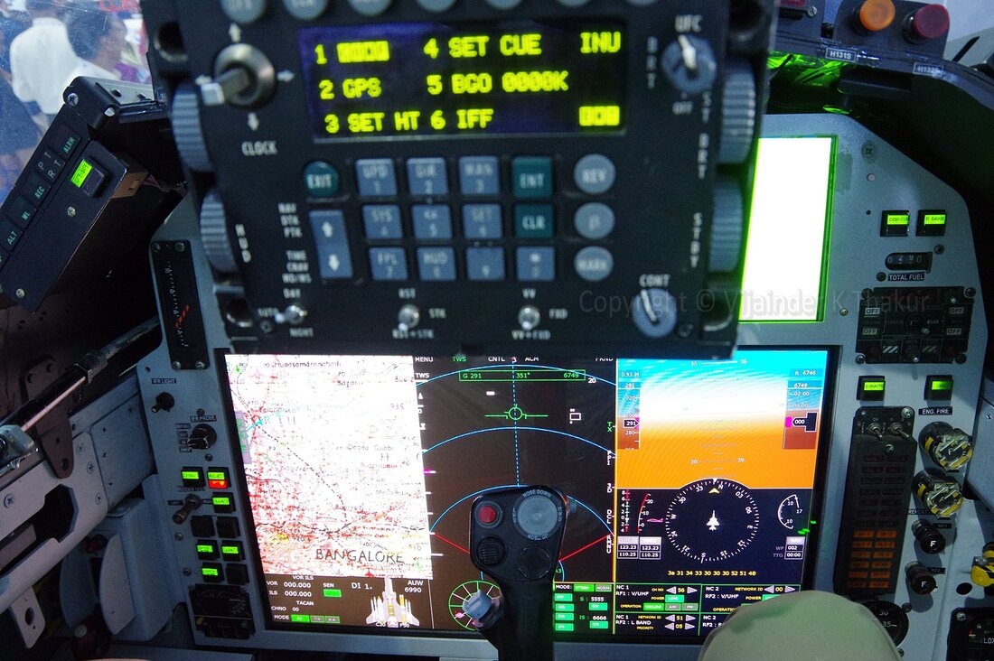
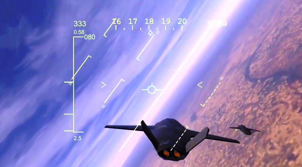
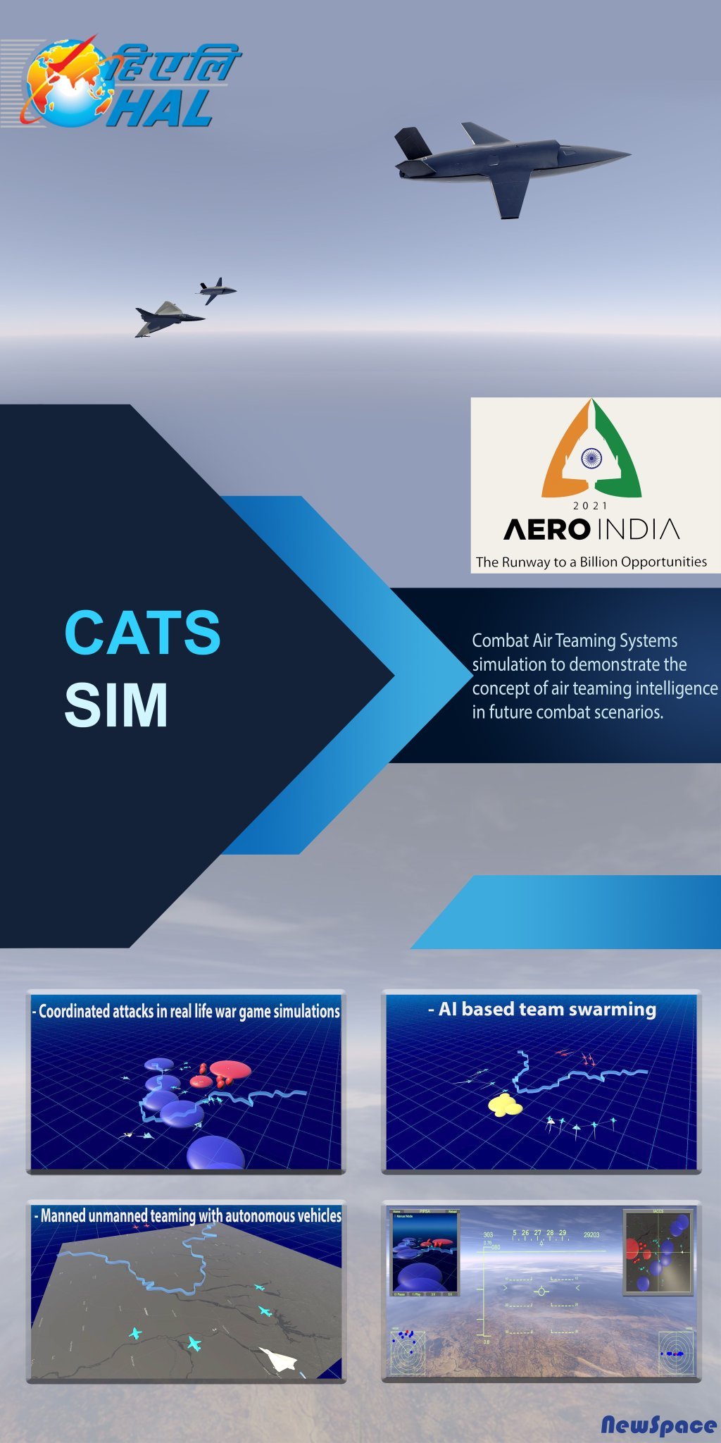
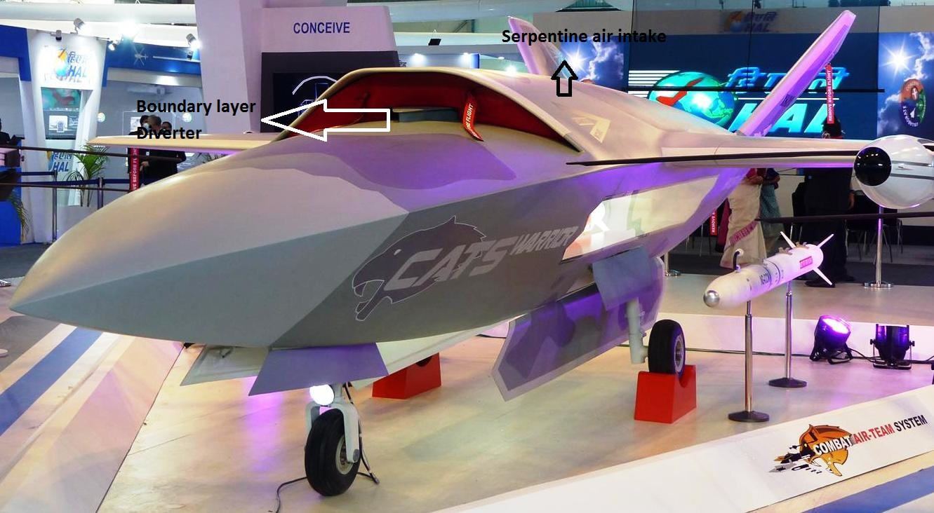
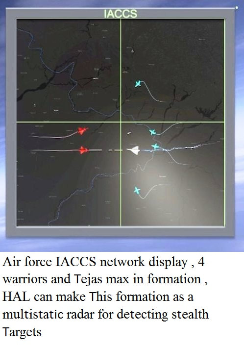
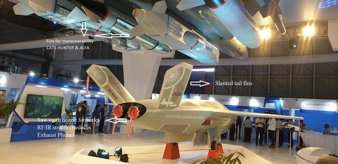
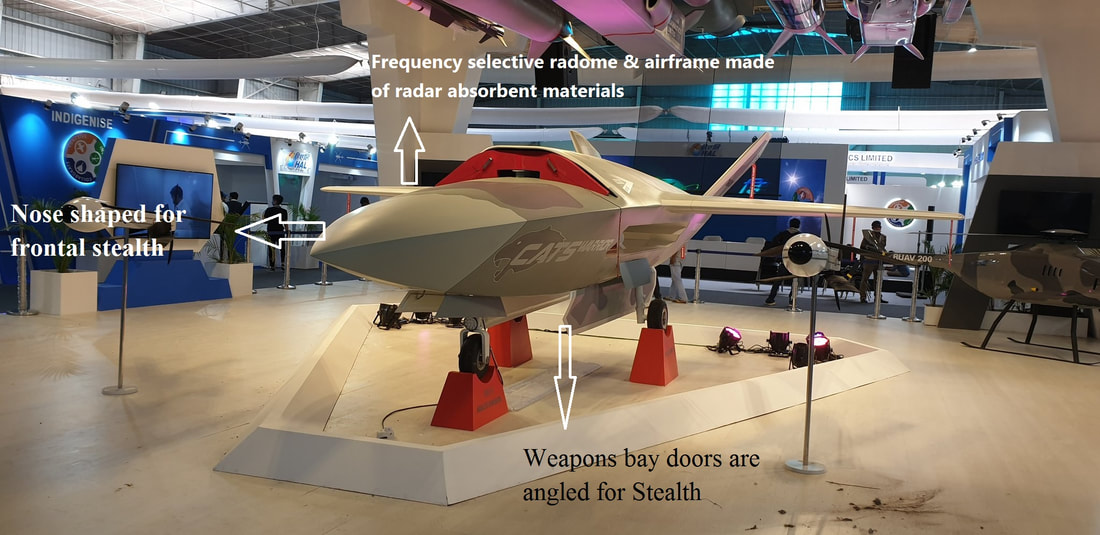
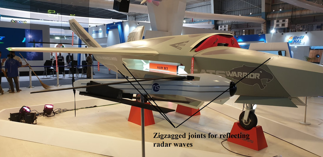
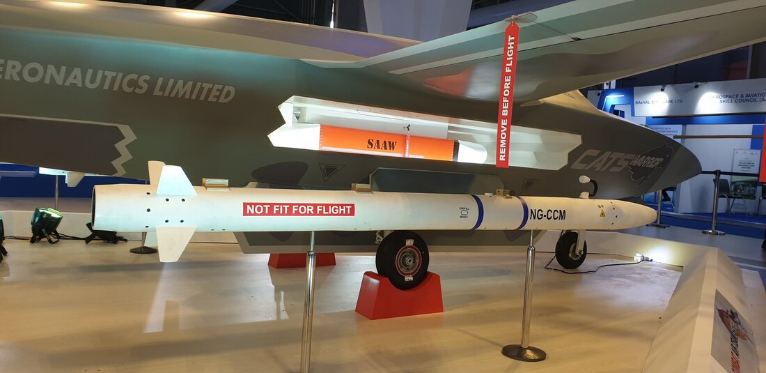
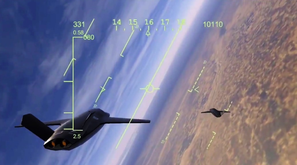
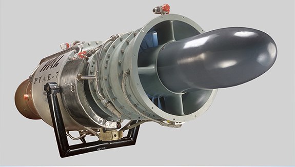
As the use of unmanned aircraft systems (UAS) in military operations has increased, so too have their capabilities. One recently developed capability is the ability to operate in conjunction with traditional manned aircraft through a process called manned-unmanned teaming (MUM-T), allowing manned aviators to benefit from the unique capabilities of UAS. UAV's have been carrying out all the missions solo but with the development of Artificial Intelligence (AI), machine learning and deep learning they can carry out missions autonomously without any control from the ground. This gives them an opportunity to execute teaming. They can be small as they do not have a pilot inside. But when they are small the sensors are small and the range becomes smaller. Therefore, they need a manned aircraft to aid them in firing long range weapons. For the past one year the HAL has been working on how to develop teaming which is based on AI. It is in this dimension where disproportionate gains are being achieved by the skillful amalgamation of the intelligence, grit, determination, tolerance for ambiguity, instant decision making capability and more of the combat pilot with the tremendous range, reach, endurance and the weapon carrying capability of the so called “dull, dirty and the dangerous” UAS. The rise of Integrated Air Defense Systems (IADS) is leading to more complex and challenging operational environments to the air forces. Teaming of manned combat aircraft with unmanned systems is one way of challenging advanced IADS like Chinese IADS, whilst bringing the additional benefit of reducing the risk to the pilots. So future is MUM-T Combat Air Teaming System Hindustan Aeronautics Limited (HAL) is developing a Manned-Unmanned System called Combat Air Teaming System (CATS), a deep penetration attack system that enables a fighter pilot to remain safely within the country’s borders, while being able to deploy UAS or swarms of drones deep into enemy territory to destroy targets. HAL had quietly initiated the CATS project in 2017 and also tested the project in Pokhran in Rajasthan for the Indian Air Force, senior officers of which were said to be impressed by watching the tests. The preliminary design work has been completed. Work is now being done to define the requirements for a future cockpit for the type capable of handling the workload. As part of CATS, future variants of the Tejas Mk-1A will act as a ‘Mothership for Air teaming eXploitation’ (MAX) and will be modified with additional command and control interfaces for this purpose. The ‘mothership’ will take around 15 months to get ready to be made compatible with CATS. By 2024-25 HAL will be able to develop the CATS. HAL started detailed design work on the separate components that comprise the CATS system. The CATS project is part of a larger dream project by HAL to develop the advanced technologies of the future. There are three reasons for developing CATS: India’s relatively limited military resources, the desire to create advanced future-class combat equipment and a tactical preference to use more unmanned assets for attacks on hostile areas. The central objective was to enhance teamwork. CATS is a system of systems, it is an umbrella system which have a mother ship based on the LCA platform. The two-seater Tejas Mk1 Trainer as ‘Mothership for Air teaming eXploitation’ (MAX) will have a pilot in front and a weapon system operator in the rear. Weapon system operator of Tejas MAX will control the UAS/swarms drones associated with each LCA. The CATS will link a network of advanced autonomous drones to a fighter aircraft which will subsequently use the drones for air-to-air, air-to-sea and air-to-ground combat. Tejas MAX mother ship is currently using as a test-bed for testing new technologies developed as part of CATS. A different system based on CATS technology for Jaguar aircraft known as Jaguar MAX customized for jaguar aircraft also under development. Currently The LCA Tejas or the Jaguar Darin III will be the choice as "mother ships”. The CATS concept can be transported into any other aircrafts of IAF including cargo and helicopters. CATS comprises three components that can be separately or simultaneously deployed –CATS Warrior (Teaming drone), CATS Hunter (air-launched cruise missile) and Alpha-S (glider drone). All three are controlled by the pilot from the mothership via a secure data links, and equipped with electro-optical and infrared sensors. Much of the work is being done by HAL, which is also partnering with Indian start-ups to deliver the programme. Scale models are expected to begin testing in the near future. Since the Tejas lacks an operational datalink, HAL is looking to integrate an indigenous datalink that is being tested on the Hawk-I. All the drones in the CATS family can work autonomously if the data link with GCS/mother ship lost. They have the intelligence where the other assets would be in the tactical scenario therefore they will do something sensible or execute the attack. All the assets in the CATS family have conformal Omni-directional UHF antennas in the top and bottom of their airframe, using these data links they are connected with each other all the time. They would be in communication with each other and with mother ship. The mother ship will be in communication with other mother ships and with the air force data link to get the data from AWACS, these data passes down to the warriors in lead. The primary user of the CATS family is IAF. HAL is also developing Army & navy variants. These variants will have different mission’s profiles and weapons package. Army & navy prefer smaller versions with Vertical Takeoff and Landing (VTOL) or any other kind of launching mechanism. Army/Navy versions will be lighter, it would have smaller engines. There would be a warrior 0.5, 0.33, 0.25 versions (size) HAL can develop these smaller versions in a matter of months; these smaller versions are already under building. The army variant will be controlled by Mobile ground controllers. HAL is not only working with IAF but also with Army & Navy to make the system operational as early as possible. Project management teams from, Air force, Army, Navy & HAL is working together to make It reality and HAL has enough money to complete the project. CATS Warrior (Loyal Wingman) CATS Warrior is an autonomous unmanned aerial vehicle (UAV) which is intended to operate alongside/ahead of the LCA mother ship as a loyal wingman. CATS Warrior is the first loyal wingman showcased, at least in mockup form, with air-to-air missiles. Warrior can take off and land autonomously. The Warrior is primarily envisioned for Indian Air Force use and a similar, smaller, version will be designed for the Indian Navy. It could be used both as a forward-deployed scout for regular aircraft as well as for directly engaging enemy targets. CATS Warrior can take off on its own from the ground and target enemy locations. The Warrior is being armed with air-to-air and air-to-ground missiles, which would be used to hit targets on the ground or in the air. CATS Warrior has a combat radius of 350km, after completing the mission CATS Warrior will return to base. If required, the CATS Warrior can sacrifice itself to crashing into the target in long-range combat missions; it can go up to 700km and hit a target like a kamikaze drone. Multiple Warriors will be commanded by a single Tejas. Currently Tejas mothership can control maximum four warrior loyal wingman drones. The idea is to maximize the effectiveness of every mission while reducing the potential of losing the lives of precious pilots since they would be accompanied by the drones which would protect them. The Warrior, is designed as a stealth platform, being small It has inherently less surface area, the airframe is built using composite radar absorbent structures allows the UAV to operate in stealth mode. Warrior airframe is shaped for stealth, nose cone, serpentine air intake on top of the airframe; weapon bays, conformal data link antennas etc are some of the stealth features. Weapons bay doors, radome etc are zigzagged to scatter the radar waves away from the radar source. Exhaust nozzle is specifically designed for defeat high frequency radars which target the drones from behind. The corrugated nozzle of warrior also helps to reduce the IR signature. These stealth features would allow it to evade being picked up by radar, which makes its detection challenging for contemporary systems. The Warrior is equipped with an electro-optic/infrared (EO/IR) payload, active electronically scanned array (AESA) radar, inertial navigational unit, and electronic warfare suite for intelligence, surveillance, and reconnaissance (ISR) and combat operations. Warrior will serve as a ‘sensor amplifier’ for the LCA, flying out ahead of the manned aircraft and using its sensors to feed information back to LCA. All the electronics and other sensors/equipments will acquire from various DRDO/HAL labs. Sources of electronics are already identified these systems are already in use with various aircrafts. CATS Warrior provided with two internal side weapons bay each can carry one Smart Anti-Airfield Weapon (SAAW) precision-guided weapon as its payload. Current version of CATS Warrior can carry two ASRAAM (NGCCM) close combat missile externally, future variants will be able to carry long range beyond visual range air to air missiles. The Warrior can also carry and release the Alpha-S, swarming drone. Each warrior can carry up to 6 Alpha-S each carrying about 5-8kg of explosives, and can target multiple enemy locations simultaneously on being released. Warrior can also carry fuel tanks external. Weapon and fuel payload is mission adaptable. The CATS Warrior is powered by modified PTAE-7 engine. Upgraded PTAE-7 engine is fitted with FADEC, better compressor, better turbine blades, longer life, better methods of maintenance and got a wider bandwidth of operation. Currently warrior is not fitted with afterburner but HAL is already tested PTAE-7 engine with afterburner module. Adding jet pipe for afterburner increases the overall weight of the drone. For the future variants HAL may use under development HTFE-25 engine. Other similar loyal wingman drones are supposed to be modular, their components, such as detection or payload delivery systems, being mission-adaptable. The modularity of the CATS Warrior was not mentioned by HAL, and the existence of the multi-purpose Hunter is partially compensating for its lack. CATS Warrior drone system should be ready for first flight by 2024-25 and the mothership integration a year or two latter. Specifications
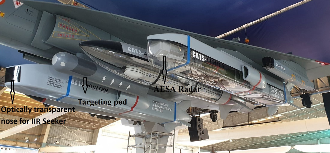
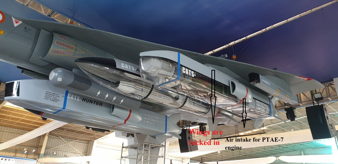
CATS Hunter (Recoverable Cruise Missile) The CATS Hunter is being conceived as an air-launched recoverable and reusable low-observable, AI powered cruise missile. CATS Hunter has the capability of deep penetration strikes. Hunter probably be the first multi-purpose weapons carriage system in the world. CATS Hunter can carry 250 kg different types of warhead in its internal bomb bay. It will have a range of 200-300 kilometers in one way. In non recoverable missions the missile acts as an Air-launched cruise missile with a range of 500-600km (need confirmation). Hunter will be equipped with a new generation navigation system, Global Positioning System, Terrain Relative Navigation, Image-Based Navigation, Automatic Target Acquisition, and will be equipped with an Imaging Infrared Seeker/ RF seeker. Hunter will use single up-rated PTAE-7 engine. CATS Hunter will have 600+ kg weights. It will be powered by an upgraded PTAE-7 turbojet engine. CATS Hunter could be integrated with Tejas Mk1A, Mirage-2000, and Su-30MKI fighter fleet initially and later on LCA Mk2, TEDBF and AMCA. Once the mothership reaches a battle area the CATS Hunter will be released from the aircraft and can do air to ground and air to sea attacks. After finishing the mission the pilot can command the hunter to go back to the base in some cases pilot can command to do a suicidal attack on the target. Hunter can also autonomously come back to the base. To aid the landing hunter has two parachutes. When the hunter reaches near the base after completing the mission one parachute which is fitted between air intakes opens and the hunter descend towards the landing point, just before impacting another parachute opens and with a slow rate of descend it touches the ground, the ground crew can collect the system. Once recovered Hunter can be refueled and rearmed for another mission in a short time period. It can reprogram with fresh sets of data such as satellite images, co-ordinates etc of its new target. With such a capability hunter can work even in intense electronic warfare/ jamming environment without requiring mid-flight updates. CATS Hunter also can work autonomously without the aid of mother ship. If CATS Hunter failed to find its target it will find another target from its threat library or abort the attack and come back to the base. CATS Hunter can also do Intelligence Surveillance and Reconnaissance (ISR) missions, Electronic Warfare missions etc. For ISR mission’s hunter will use surveillance sensors, jamming sensors. During ISR missions its bomb payload is supplanted by fuel it can stay airborne for a long time to carry out jamming, reconnaissance and post-action filming of strike zones .After the mission (any mission) it come back to the base and the data available can extract for evaluation & for future use. During the mission using data links hunter can communicate with Ground Control Stations and can pass data real time. One Tejas can carry maximum 5 hunters. Specifications
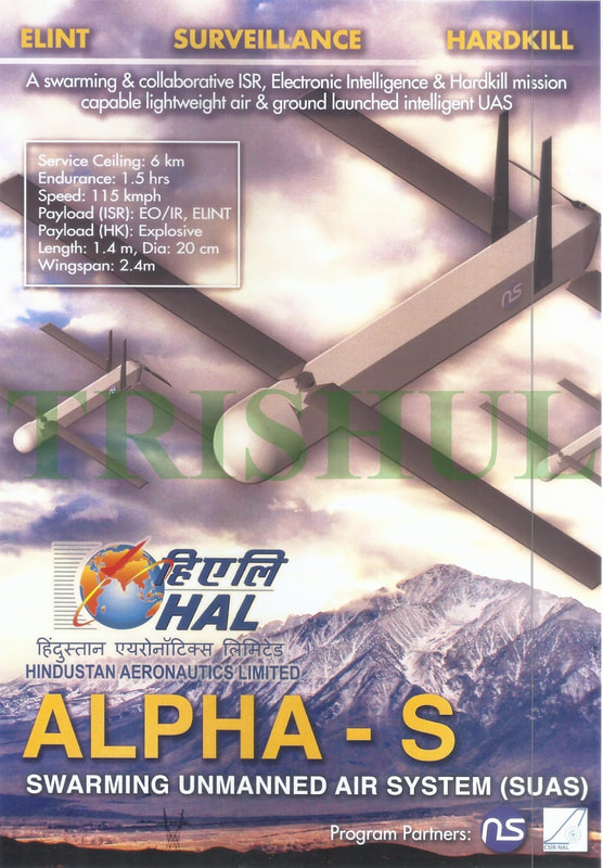
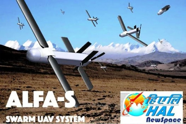
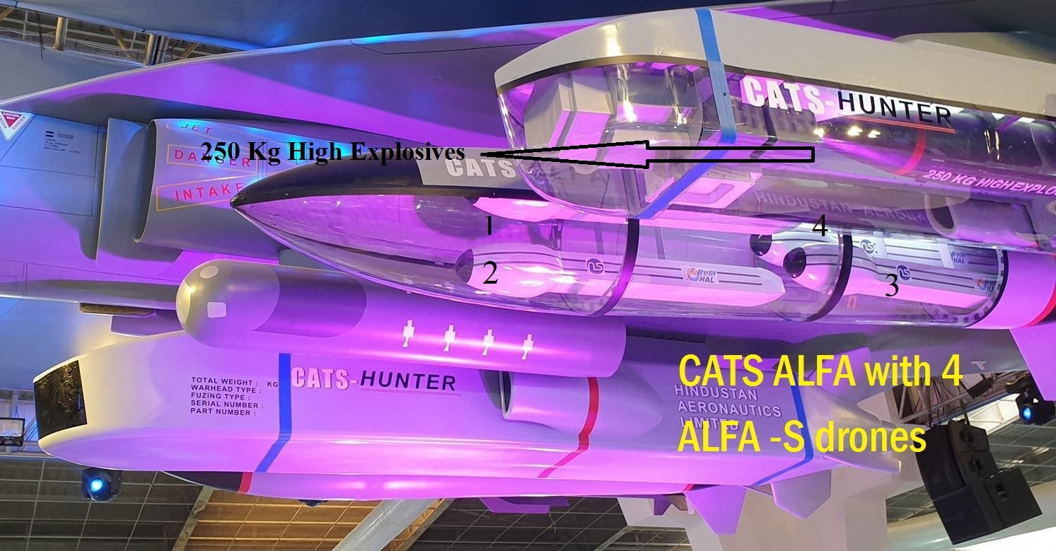
CATS ALFA (Air Launch Flexible Asset) CATS ALFA is a carrier for ALFA-S Swarming drones. The ALFA-S drones are packed inside CATS ALFA carrier. This is a glide pod, LCA can carry maximum 5 CATS ALFA glide pod. The first ALFA-S drone prototypes are likely to be deployed from Hawk Advanced Jet Trainers. In a mission CATS ALFA carrier drops from the aircraft and can glide 50 to 100 kilometers (need confirmation) into the enemy territory and once it reaches the mission zone, The glide pod opens up by command from pilot/ autonomously and swarm drones comes out and do the mission . The same drone can execute multiple missions or different drones can be designed for different missions. Each CATS ALPHA pod can carry 4 ALFA-S swarming drone in a foldable wing configuration. ALFA-S swarming drones have two folding wings and are between 1 and 2 meters long. After detaching from the carrier pod ALFA-S can further glide into 100-150km, total range of CATS ALPHA / ALFA-S combination is somewhere 150-250 Km depends on the altitude of mother ship and other environmental conditions. Each Alpha-S weighs around 25 kg and can carry a payload of 5-8 kgs. A single Alpha-S can target several enemy locations through artificial intelligence and machine-learning technology which allows the ALFA-S to discriminate between possible targets. When deployed, the drones fly in formation at speeds of 100 kmph. The drones in the swarm of Alpha-S are networked via electronic data links, and equipped with electro-optical and infrared sensors. Using their infrared and electro-optical sensors; they detect targets such as surface-to-air missile units, enemy radars and aircraft on the ground. Each drone is designed to be smart enough to 'learn' about what it detects before targets are assigned to individual drones. Each drone then carries out a suicide attack - hitting the target using the high-explosive warhead carried onboard. Each swarm could have dozens of individual drones. If detected, some of the drones would be shot down, but the sheer numbers of the swarm would overwhelm enemy defenses and ensure a high probability of mission success. According o brochures ALFA-S can be used for ISR missions fitted with EO/IR and ELINT sensors. Specifications
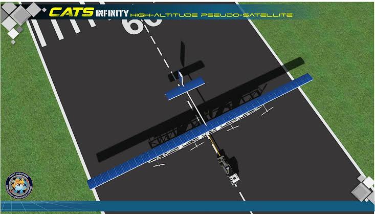
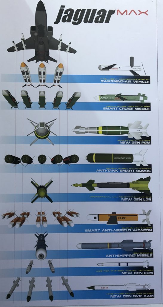
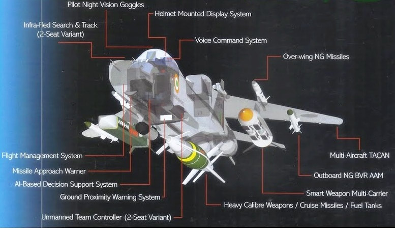
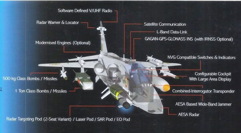
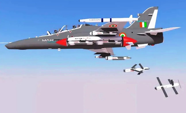
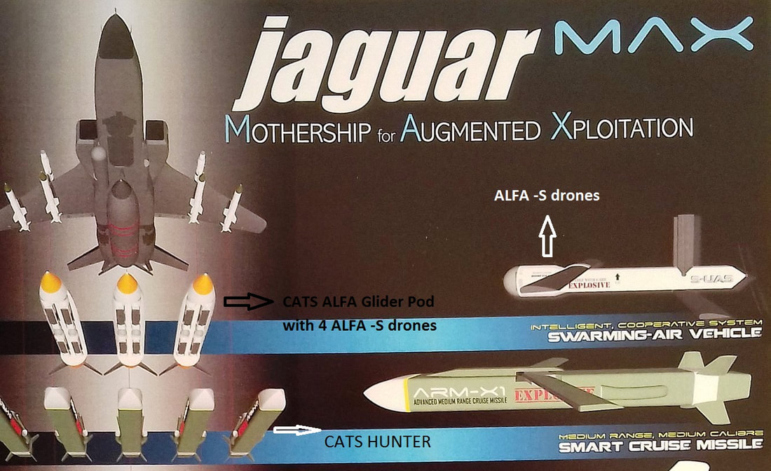
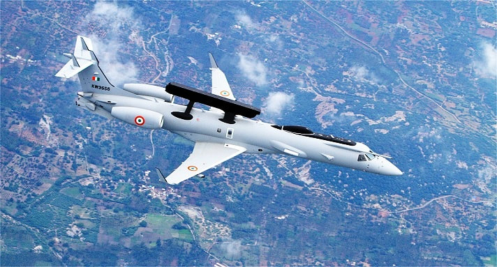
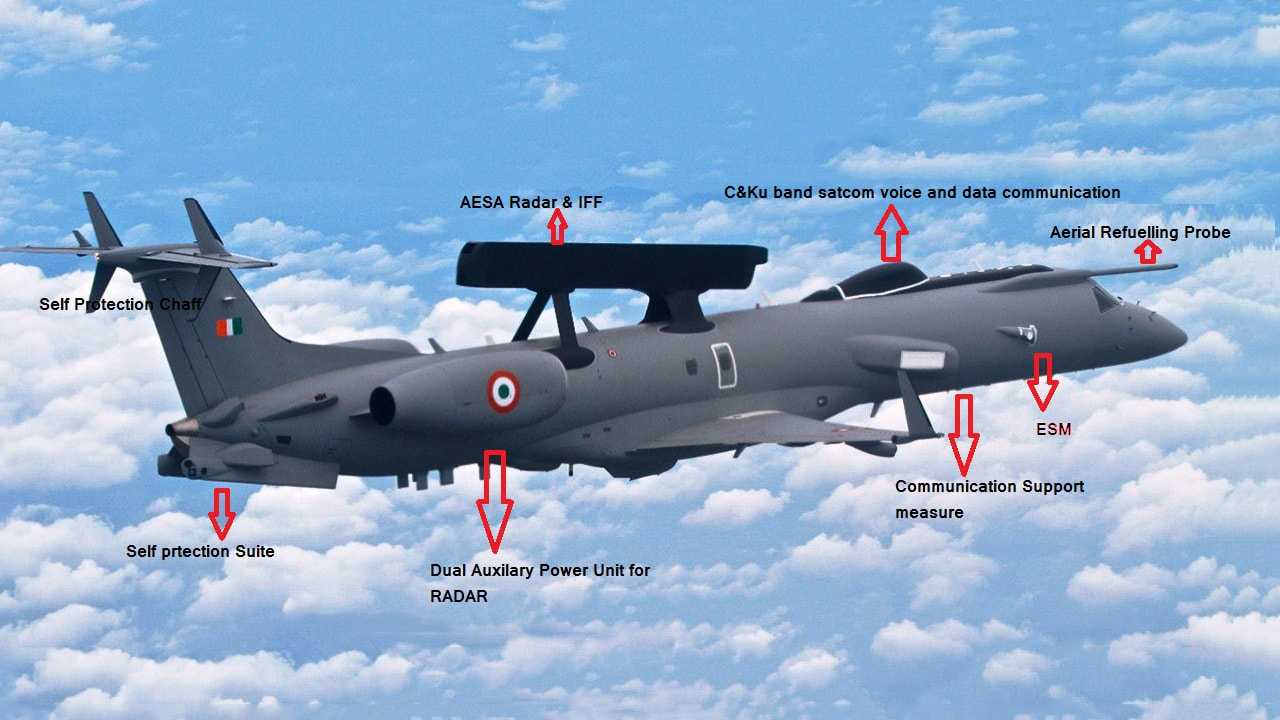
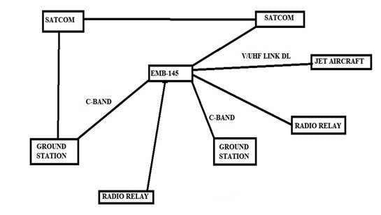
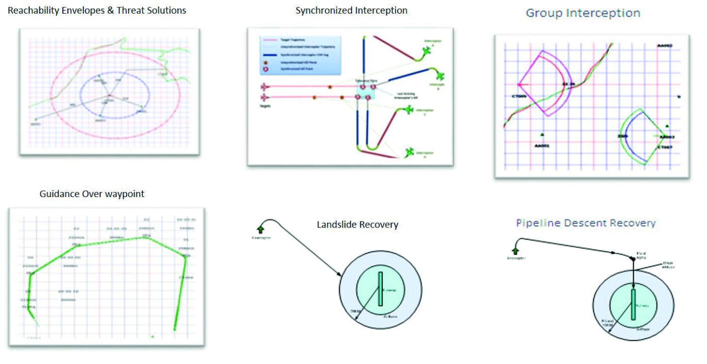
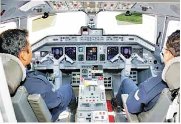
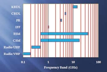
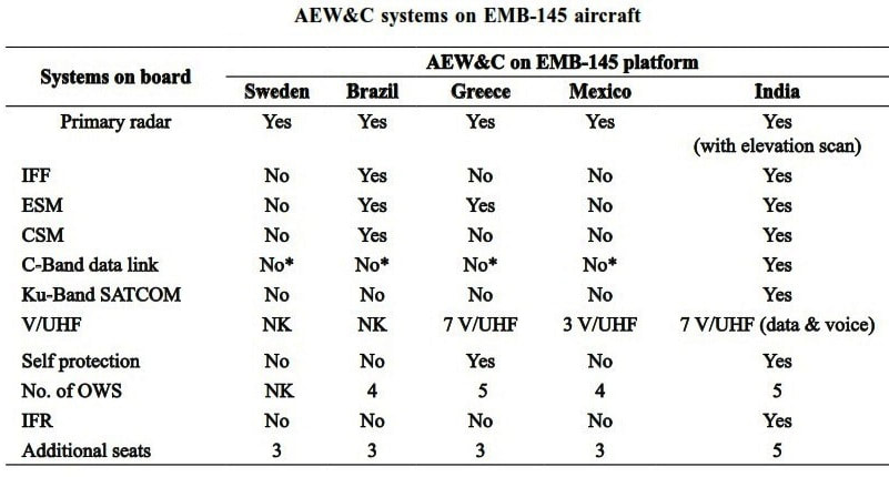
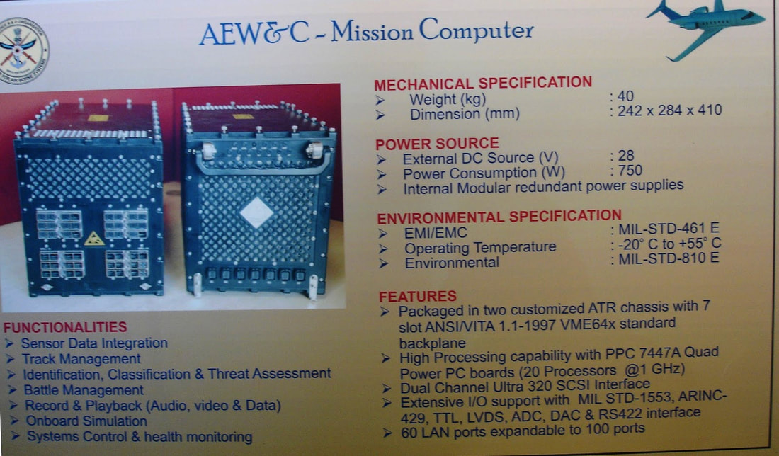
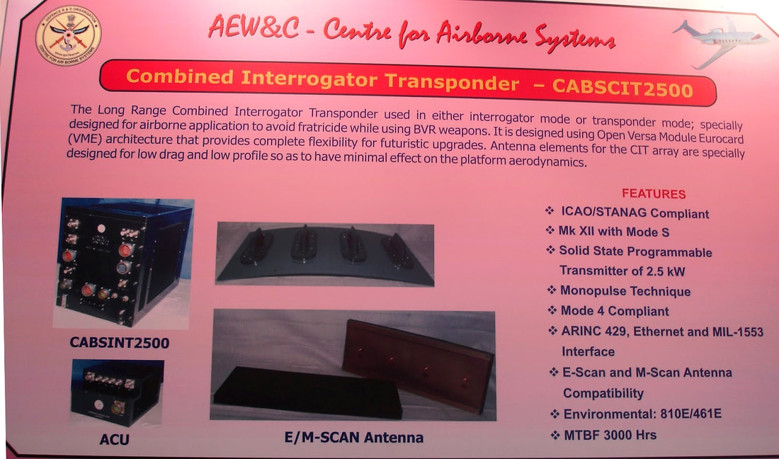
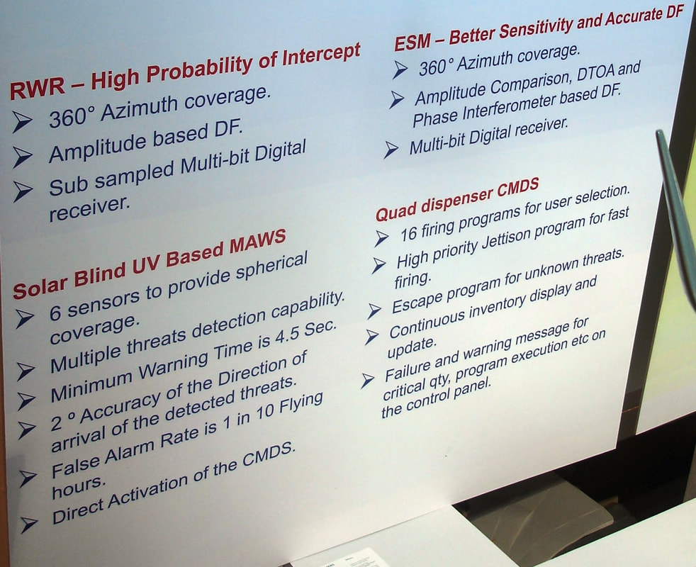
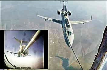
CATS Infinity As part of CATS, HAL is also developing a high-altitude pseudo satellite system CATS Infinity that can fly at about 70,000ft continuously for 2-3 months, to maintain surveillance on the ground below. This is a futuristic concept which no other country has yet developed. It will be a solar powered system. HAL is developing this jointly with a startup. CATS Infinity will act as a data link relay station between various assets of the CATS family. It will be equipped with advanced sensors such as synthetic aperture radar and other surveillance equipment's. CATS Infinity can cover larger areas with less interference. They could also help ease data transfer when used as an intermediate conduit between a satellite and UAVs. Infinity would help to coordinate attack missions of CATS, and also helps in providing Battle Damage Assessment (BDA) via live video feeds and images to determine if the mission was successful and to plan the next course of action. All research and development of the aircraft was done in-house, which is being validated by aerospace major Boeing. The first flight of High Altitude Pseudo Satellite was scheduled for 2019 but delayed. ACID (Air Combat Intelligence Development) To support the Manned and UnManned Teaming operations (MUM-T), an advance artificial intelligence (AI) based combat algorithm is being developed under a program called Air Combat Intelligence Development (ACID). Developed by The IAF and Bengaluru-based start- up New Space Research & Tech ACID utilizes deep reinforcement learning (DRL) to increase the efficiency of the algorithm based manned unmanned teaming implementation towards future ops. Jaguar max The glimpses of HALs manned unmanned team system was first broke cover in aero India 2019 as Jaguar max. CATS Hunter, a SCALP-like cruise missile, as is the CATS ALFA-S switchblade swarm drone was displayed at Aero India 2019 as a teaming system with a Jaguar weapons upgrade package by HAL. HAL displayed new avionics, a cockpit, and a model of the heavily armed upgraded Jaguar ground-attack aircraft. The Jaguar MAX primarily features an EL/M-2052 active electronically scanned array (AESA) radar from Elta, an AESA-based wide-band jammer, a combined interrogator transponder, a flight management system, a configurable cockpit with a larger area display, a voice command system, a helmet-mounted display, an L-band datalink for long-range missions, a GAGAN/GPS/GLONASS-aided INS (with IRNSS optional), a software defined V/UHF radio, and modernized engines (optional). The aircraft can be configured with a Radar Targeting Pod (2 seat-variant)/Laser Pod/Synthetic Aperture Radar (SAR) Pod/Electro-Optical (EO) Pod to meet various mission requirements. The Jaguar MAX is envisioned to carry and launch various next-generation air-launched weapons, including a gliding heavy-weight new-generation precision-guided monition; five sensor-based, multi-warhead, anti-tank smart bombs; a new-generation laser-guided bomb; 16 gliding, lightweight smart anti-airfield weapons; a sea skimming anti-ship missile; two new-generation short-range air-to-air missiles; four next-generation beyond visual-range air-to-air missiles; five advanced medium-range cruise missiles; and 12 swarming unmanned air vehicles. What is AEW&C? AEW&C system is a potent force multiplier, providing surveillance, tracking, identification and classification of the Airborne/Sea surface targets. The information from multiple sensors are collated, associated and fused to provide a cogent and comprehensive air situation picture on configurable consoles. Further capabilities include threat assessment and enabling the interception of the hostile targets through guidance of own interceptor. Introduction The development of an indigenous Airborne Early Warning and Control System (AEW&C) was taken up by DRDO & IAF in 2004. Development of indigenous AEW&C system as a mission mode programme commenced with appropriating Centre for Airborne Systems (CABS), Bengaluru, as the nodal agency. The development was taken up based on operational requirements evolved jointly by a team of DRDO and IAF. The platform for the development was specified by the IAF as EMB-145 executive jet manufactured by M/s Embraer of Brazil. After the sanction of the programme, IAF revised the operational requirements in tune with their emerging war fighting scenario. The revised operational requirement necessitated building of an AEW&C system on a small aircraft with all the systems and functionalities similar to that of the bigger AWACS being procured by IAF. DRDO took up the challenge and has made the systems a reality. The AEW&C aircraft is a derivative of Embraer ERJ-145 extensively modified and customized to house the indigenous mission systems developed in India. The complete integration of the mission system and its flight evaluation has been carried out in India. One of the main features of the aircraft is that it is the Embraer executive jet aircraft to have air to air refueling. The system was envisaged to have full net centric capability through multiple LOS and Satellite Communication Data links, on-board Mission Computer, which enables the operator to carry out the information fusion, mission control, and reconfigurable operator consoles for the operator to interact with the system and exploit the system capabilities in tune with the operational environment. The AEW&C system is a system of systems having primary radar (PR), secondary surveillance radar (SSR), electronic support measure, communication support measure (CSM), ‘C’- Band Data Link (CBDL), ‘Ku’- Band SATCOM data link (KBDL), V/UHF communication link working in the microwave region. These subsystems are mounted onboard an EMB 145 aircraft, the Indian AEW&C system is versatile in choice of the sub-systems and its capabilities. Equipment's
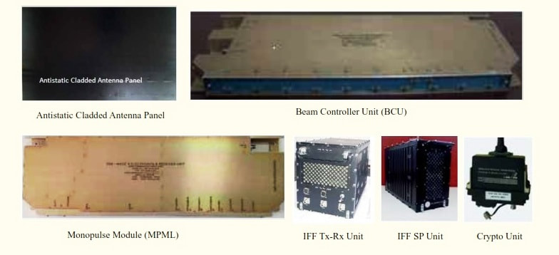
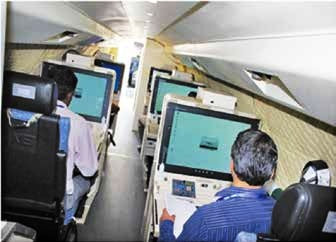
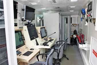
All the above systems are electrically and functionally integrated through a high speed LAN and complete suite of tactical software fully developed in house. This software provides functionalities such as multi sensor tracking and data fusion, multi target tracking, identification and classification, system control and monitoring interception and battle management functions, all of which are developed in house. A comprehensive Human Machine Interface again developed in house, projects the real-time air situation picture, into five reconfigurable consoles, in a manner required by the individual operators. In addition to the airborne complement, five major ground systems supporting all aspects of planning, training, maintenance, and integration with IAF Command and Control Centre also have been developed fully indigenously. These are:
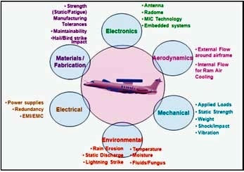
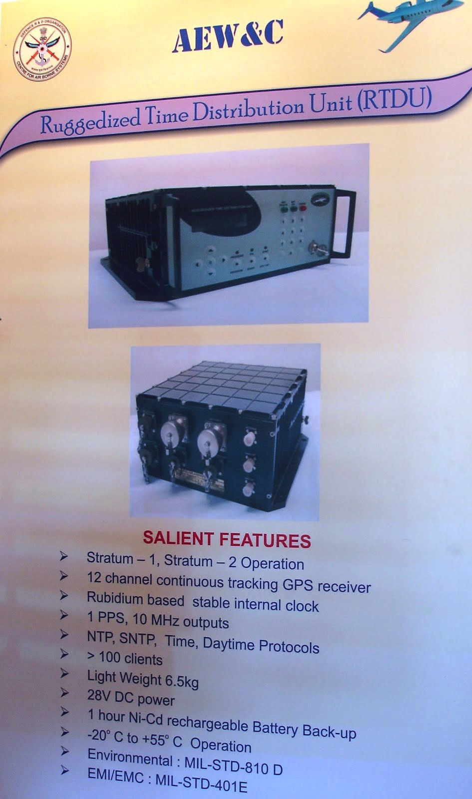
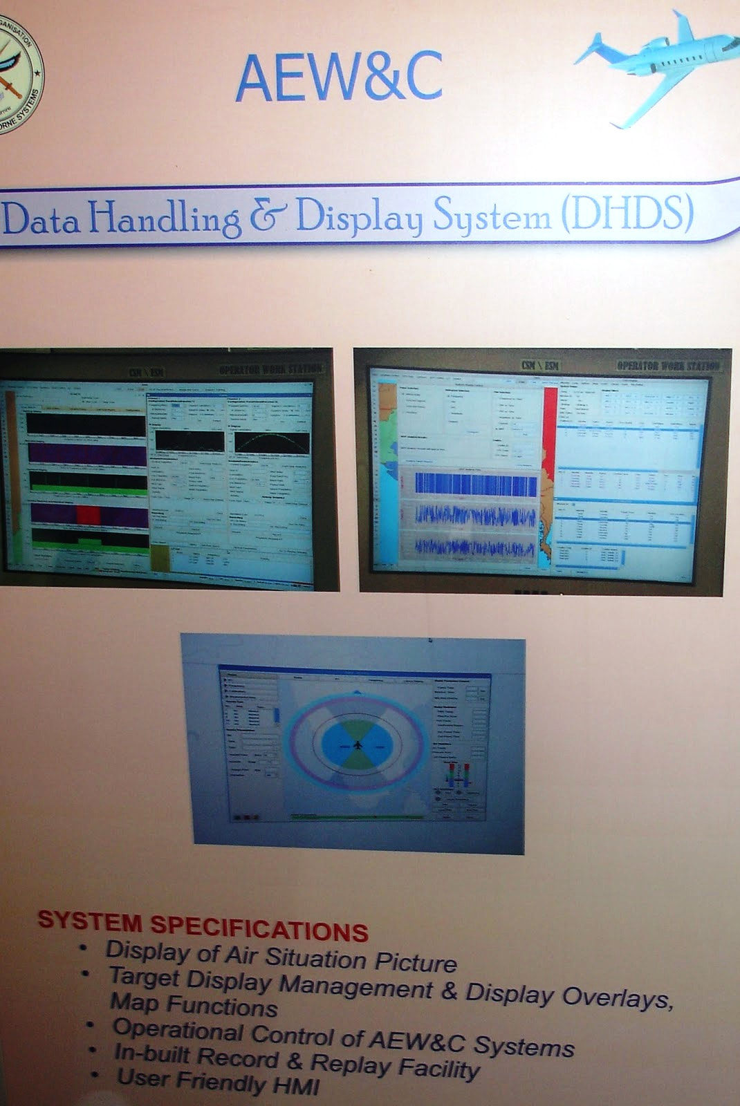
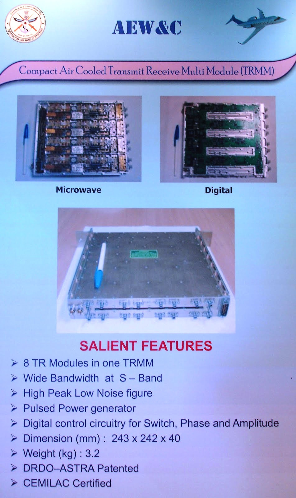
All of these are backed by a regular post development support project taken by CABS to enable operational and maintenance support to the IAF for a period of three years. The AEW&C system has undergone extensive flight evaluation flying close to 1500 hrs (700+ sorties). These include flying at Bengaluru, evaluation campaigns at various IAF bases such as Jamnagar, Bhatinda, Jodhpur, Gwalior, Agra, Chabua to state a few. Evaluation of the system also includes evaluation through conduct of Large Fleet Engagement exercise (more than 25 of them) to evaluate the complete performance capabilities of the AEW&C command, control, battle management, etc. The AEW&C system is being integrated with the IAF’s Command and Control System. Specifications Range: 250-300km Aircraft range: 3700km Service ceiling: 3700ft Maximum speed: Mach 0.8 Sensor arrangement In AEW&C, the real estate available on board the aircraft is limited and hence antennae are to be kept in close proximity to each other. On the exterior of the AEW&C aircraft, there are 89 antennae and sensors located in a cramped condition. In addition, aircraft body being metallic, the individual antenna radiation pattern gets distorted due to ‘body effect’. Hence, prior knowledge of the individual antenna radiation pattern alone cannot help while selecting suitable locations on the exterior of the aircraft for various antennae. Moreover, aircraft safety being of the highest priority, the ideal location requirement from antenna radiation pattern point of view has to take a back seat. The first step toward location identification is to predict the antenna radiation pattern with ‘body effects’. For this, one has to resort to any of the computational electro-magnetic methods. Commercial tools such as E-Mind have been used for this. This exercise is recitative and time consuming. Depending upon the number of locations tried for each antenna, one generates voluminous data. In general the antenna location process went through the following steps:
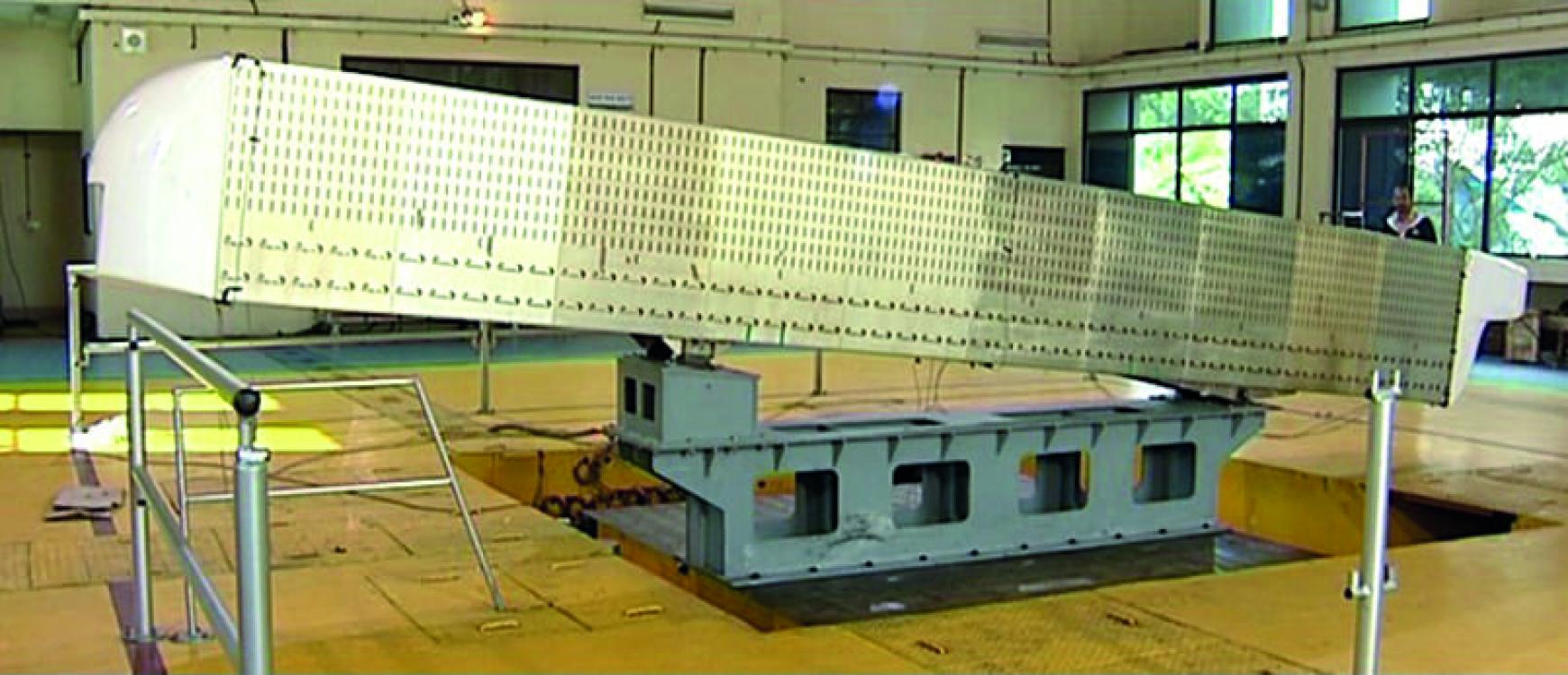
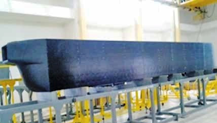
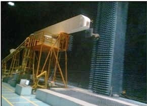
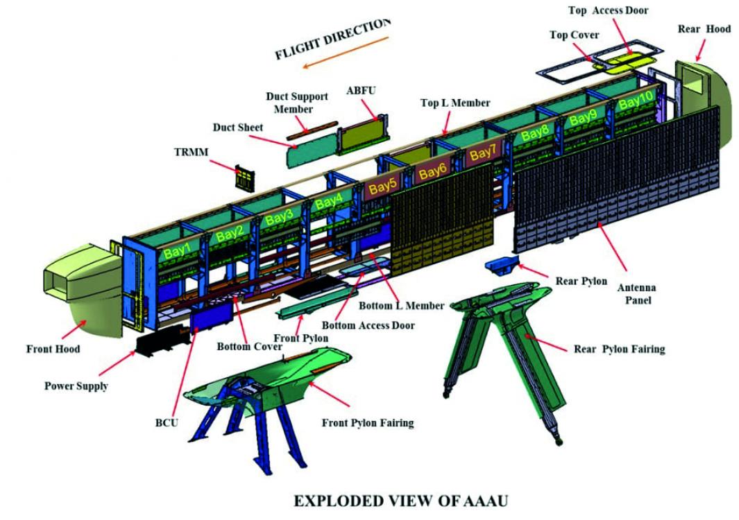
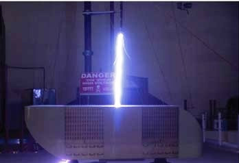
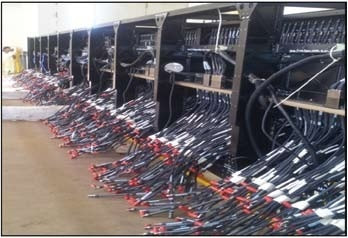
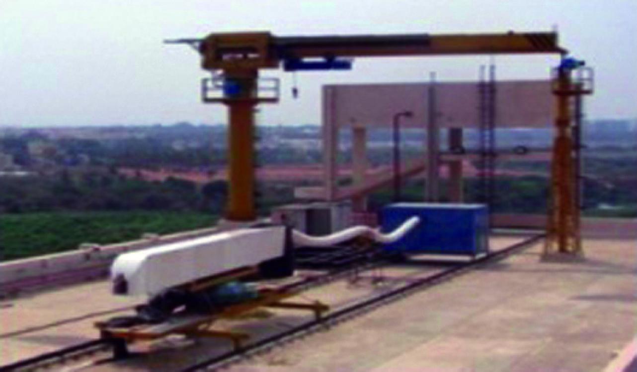
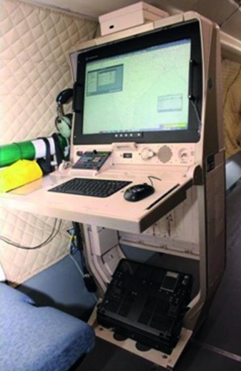
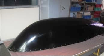
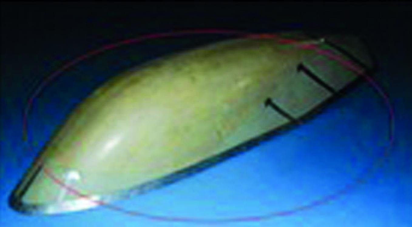
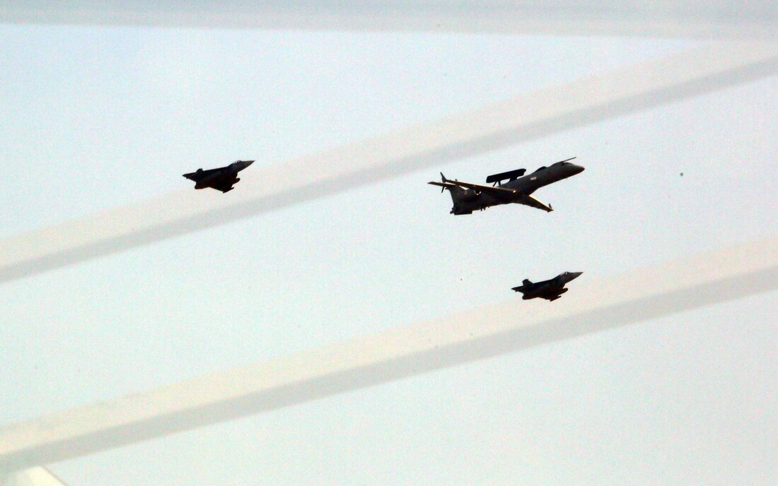
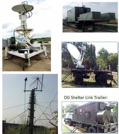
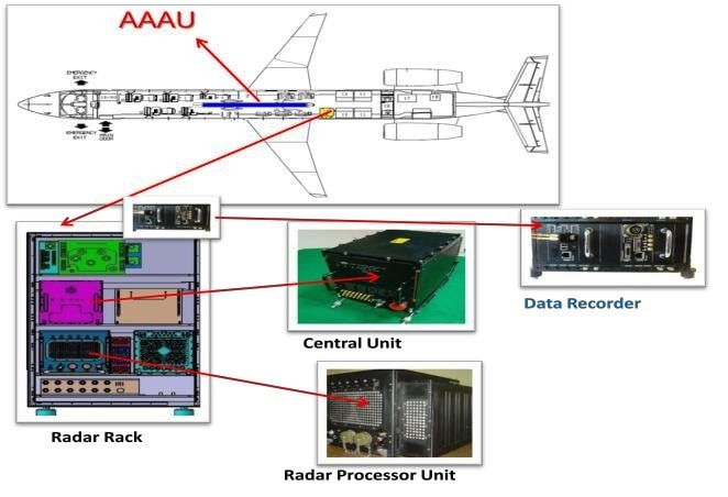
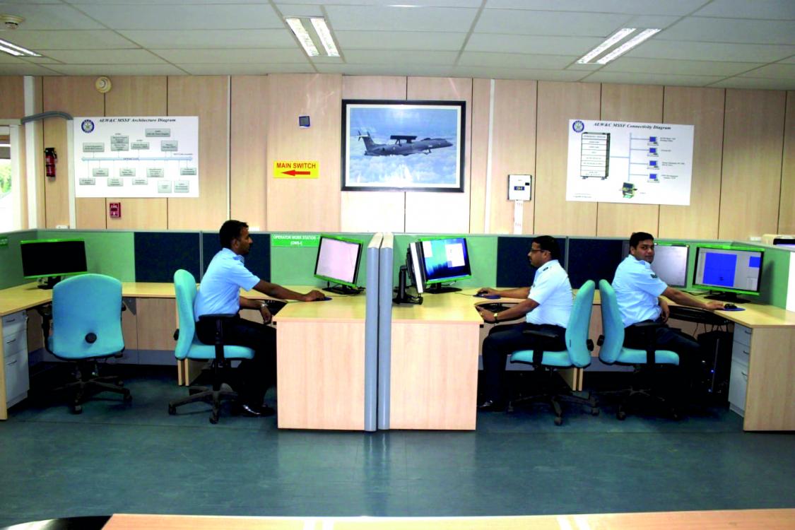
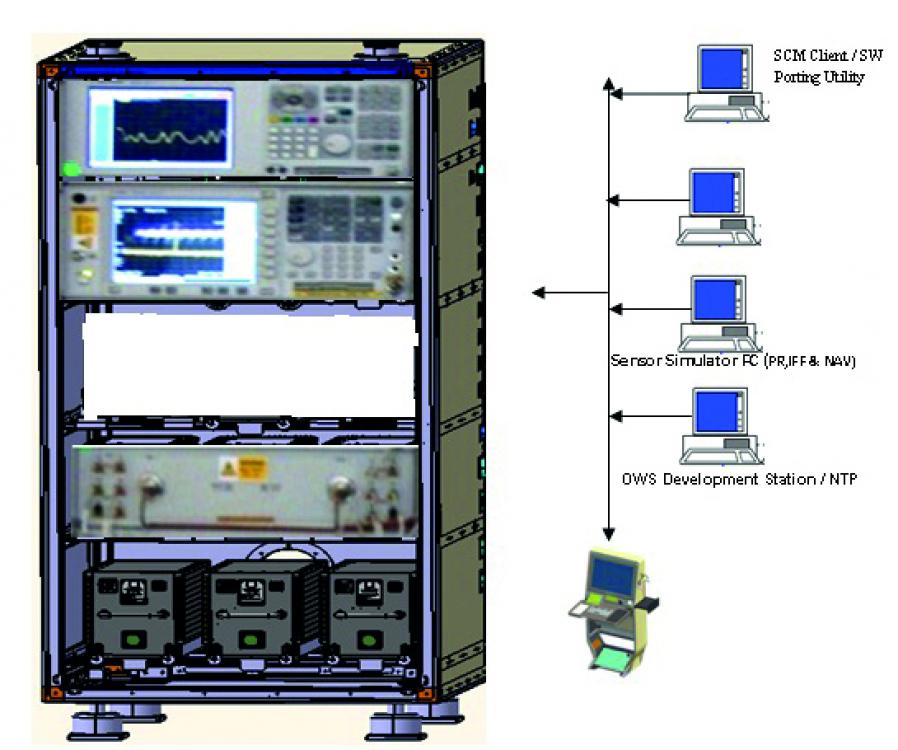
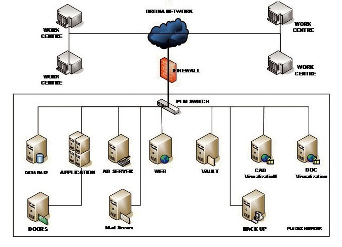
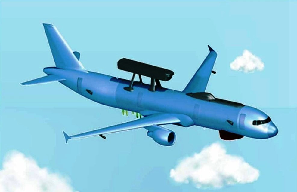
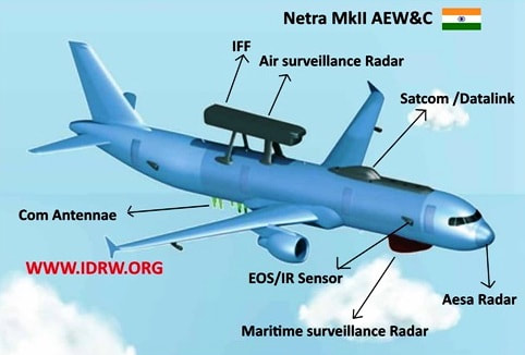
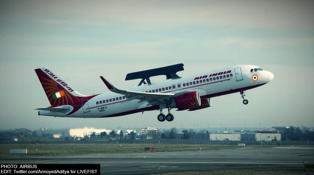
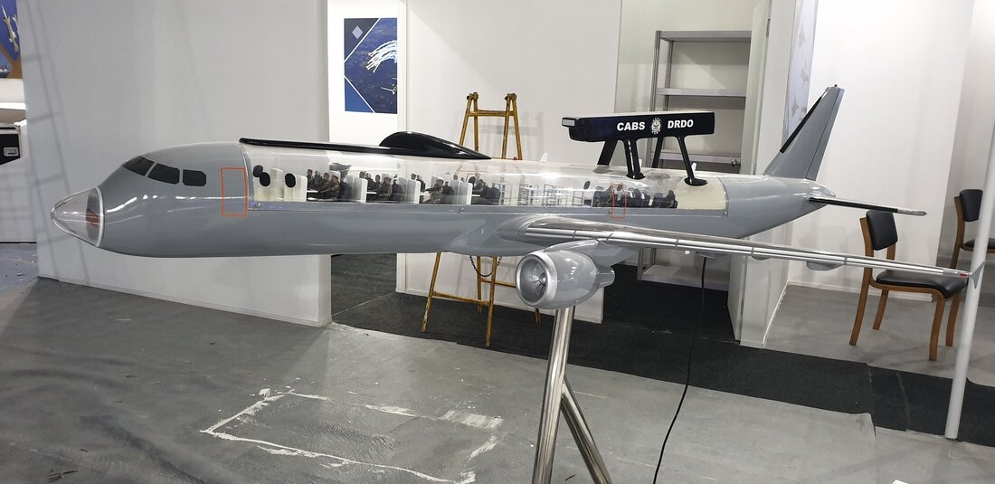
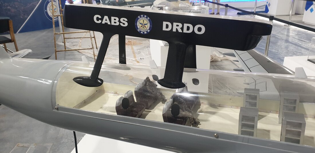
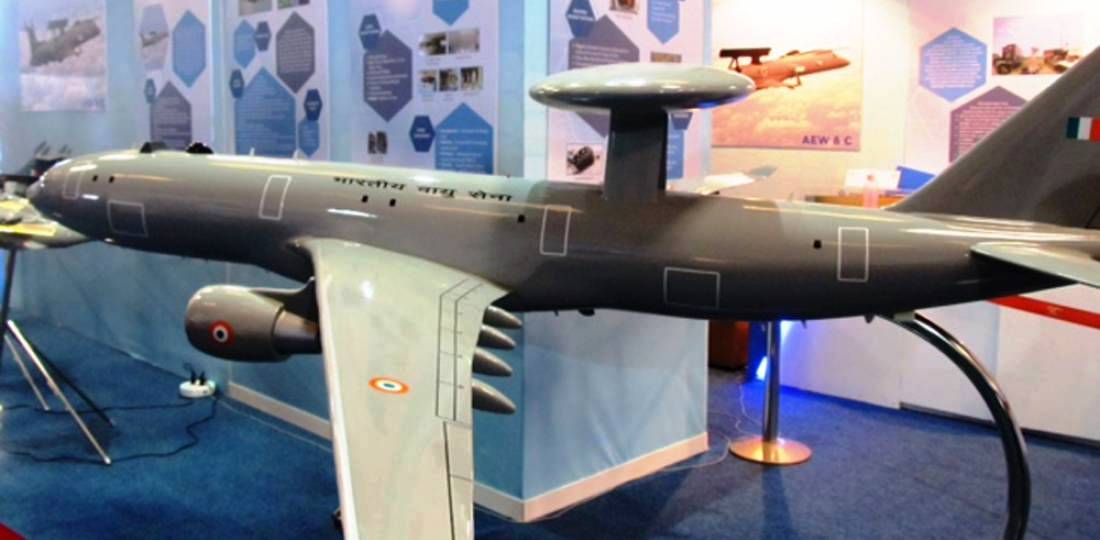
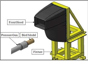
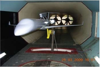
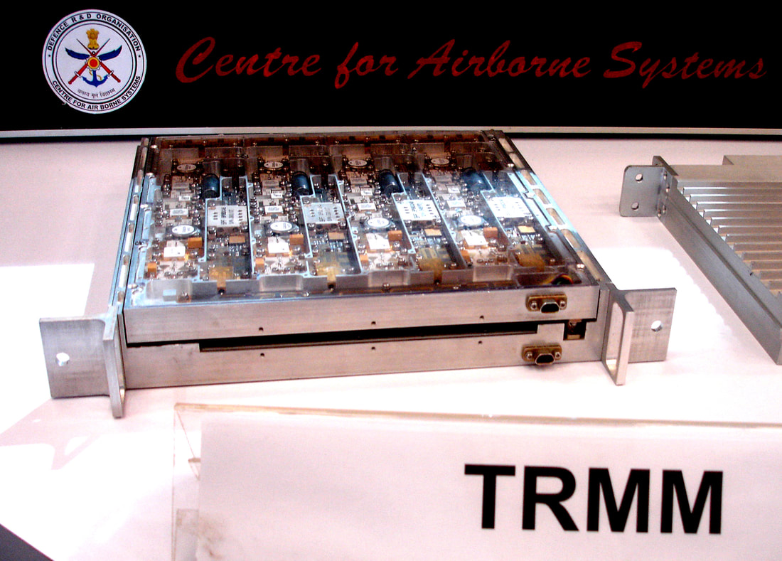
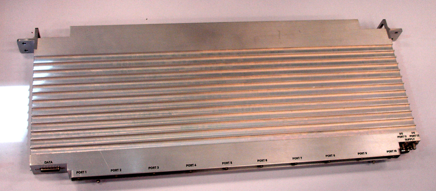
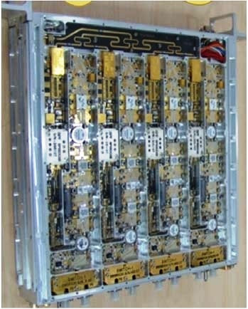
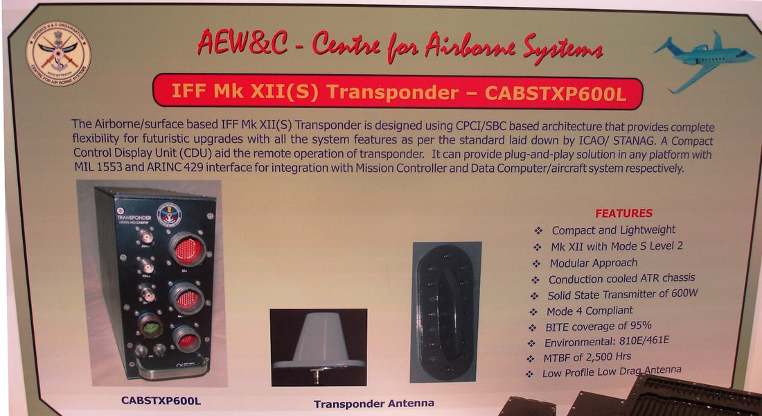
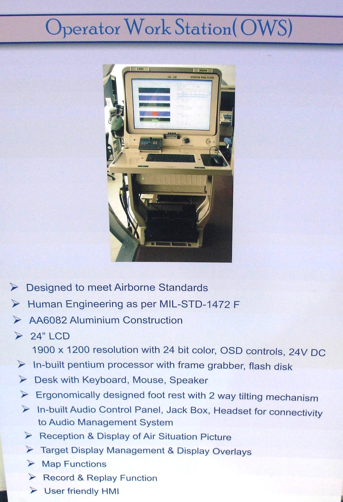
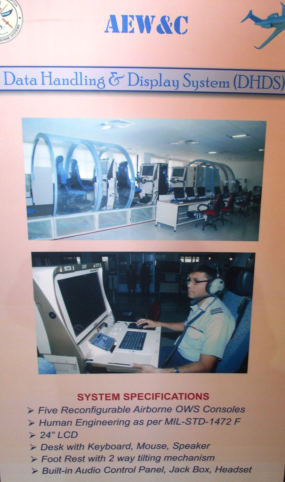
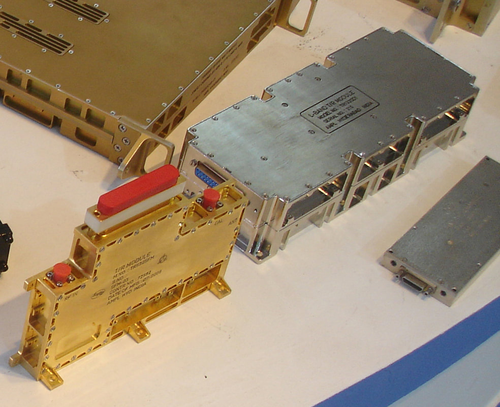
The location of the SATCOM radome adjusted forward to allow sufficient air for the active antenna array unit located in the rear under all ‘angle-of-attack’ conditions. Similarly, the AAAU itself was moved forward to avoid damage from a possible broken engine blade leading to a flight hazard. Additional fins had to be added to stabilize the aircraft under ‘side-slip’ conditions as there was a blockage of air to the control surface. Active electronically scanned array radar Active Antenna Array Unit (AAAU) is a major as well as critical component of the AEW&C system and has been indigenously developed state-of-the-art technology. AAAU is an active electronically scanned array (AESA)-based radar having more than 1,000 elements producing several tens of kilo watts of power. The AAAU is mounted on dorsal side of the aircraft fuselage using four pylons. Being an external structure of an aircraft with the dimensions of 8.2m X 0.9m X 0.5m, it qualified stringent airworthiness requirements. AAAU structure is designed for aerodynamic loads, inertia loads and aero-elastic requirements. The mechanical design of AAAU is designed considering easy accessibility for various electronic components (LRUs) inside the AAAU. The fool proof design of AAAU caters for antenna structure, thermal, microwave electronics & digital electronics. Wind tunnel tests and CFD studies were conducted for the AAAU to optimize the aerodynamic shape of front and rear hood and to estimate the internal and external aerodynamic loads. Structural tests such as Modal Analysis Test (MAT), Static Strength Test (SST) and Ground Vibration Test (GVT) were conducted and validated with Finite Element Analysis. Internal design is made to optimize the cable routing, for accommodation of front end electronics of primary & secondary surveillance radars and cooling of them. This design, using ram air for cooling the electronics inside the AAAU, drastically reduces the burden on the cooling system virtually to one third and consequently the power that is required for cooling is also reduced. The front hood and antenna panels were structurally optimized, tested and certified for bird impact requirements specified in Federal Aviation Regulation (FAR– 25). The radar offers multifunction, multi-mode capability with highly agile beam steering and electronic beam stabilization by the array. Radiating interface, the major subsystem of the PR Active Electronically Scanned Array (AESA), is first of its kind. To obtain higher sensitivity, the AAAU is designed with high power transmit capability and also achieved ultra-low side lobe level in the receive mode. The AAAU array has been developed with amalgamation of analog and digital electronics, microwave & electrical technologies. Its sophisticated electrical power distribution system comprises enough safety measures. The performance of the array is maintained by in-situ calibration system. Critical building block that supports all functional requirements of the radar and serves as heart of the AAAU system are TRMMs. The TRMM’s also have RF and digital manifolds to accommodate the size and weight due to its unique design. The unique design of integrated antenna aperture for both primary and secondary surveillance system along with cladded radome has reduced the weight and volume constraints. This uniqueness has also helped in bringing out the microwave losses thus making it a win-win from both structural and electronics aspects. With the aid of several stages of RF distributer and combiner networks single RF signal input is fed to all elements of planar array. The received signals from all elements are combined by TR modules and stages of RF combiners. To achieve the command & control of installed LRU’s of AAAU system a controller has been devised with required hardware and software. The unit accepts the control and commands information from central unit/IFF SP/MSC through specific interfaces and distributes the same to AAAU LRU’s. The bottom portion of the AAAU contains the Multi-output power supplies (MOPS) that require more cooling than the TR modules that are placed in the middle. The internal airflow for each of the 160 Transmit-receive multi-modules (TRMM) should be not less than 15 CFM even under blockage conditions due to the presence of SATCOM radome under all pitch- and yaw-conditions. To assess the required quantum of airflow, wind tunnel tests were carried out apart from CFD analysis. The system has about 2 km length of RF cables in the air passage. Safety against bird strikes is another vital requirement for AAAU being a large airborne antenna system. This calls for selection of proper material and structural design for the AAAU. The criteria are such that after the bird strike, there should not be a cause for any flight-safety concern. The debris from a damaged antenna beyond a certain size, for example, should not be able to enter the engine. The carbon composite front hood with aluminum mesh and the aluminum slotted array are designed for such a criterion. Apart from transient analysis, actual test is also conducted with frozen bird of 4-pound weight. Another special requirement for the airborne antenna is that it has to pass the lightning test for both direct and indirect effects. After zonal analysis, the lightning attachment points are identified and provided with paths for lightning to pass through without causing any structural damage. The indirect effects can be equally damaging like direct effects on items like the TRMM with sensitive electronics. The lightning must be discharged as much as possible by limiting the current flow in the skin. The waveguide slot array is best suited for this environment. Similarly, the SATCOM radome in the lightning prone zone has button/strip type lightning conductors to retard the lightning effect. Being external to the fuselage, the cross section of the AAAU perpendicular to the aircraft flight path should be minimal to have low additional drag. Hence, a low drag design was done by suitably designing the antenna panels as integral structural parts of the AAAU and eliminating the need for an additional protective radome. This has not only reduced the drag but also the total weight of the AAAU. After analysis, four antenna panels were joined to form a lager single panel to enhance torsional rigidity. FEM analysis was carried out on and found to be meeting the FAR-25 requirements. The most critical technology element for the radar is the Transmit-receive multi-module (TRMM). Design of the TRMM was carried out in the microwave lab and evaluated in detail. The most difficult part of the design was thermal management of the components in the TRMM without giving rise to hot spots by usage of ram-air-cooling. Secondary Surveillance Radar Secondary Surveillance Radar (SSR) is another important sensor in AEW&C system used for detecting targets, identification as a friend or foe while working in tandem with Primary Radar (PR). This information is very vital in the wartime and is also useful to form database during peace time surveillance. SSR system also called Identification Friend or Foe (IFF) system in military terminology comprises of an interrogator fitted with the main radar system on airborne platform and a transponder fitted on target aircraft. It operates as per the recommendations of the International Civil Aviation Organisation (ICAO) and STANAG 4193. The interrogator transmits pulsed signal in a particular mode of interrogation in a specified direction. Aircraft fitted with compatible transponder receives the interrogation signal and replies back in the form of another coded signal to the interrogator for processing and identification. The reply provides additional target details such as height, range and azimuth, and target status like communication failure, emergency and hijack. Mode 4 is an encrypted mode of operation that enhances its capability to be secured, jam resistant and resistant to spoofing. Operation in Mode S (level 2) gives capability of selective addressing and data link capability, which are very critical in dense air traffic. Based on the requirements of the user and platform constraint, the high power airborne IFF MK XII(S) interrogator has been developed for the AEW&C programme with a range of more than 375 km using modular approach. It comprises of Electronically Scanned Antenna Array (ESAA), solid-state transmitter, dual channel monopulse receiver and signal processor. All the LRUs of IFF system have been qualified as per the MIL STD 810E/461E/704D and certified for airworthiness by DGAQA/CEMILAC, and has been thoroughly tested in System Test & Integration Rig. More than 700 user evaluations were carried out by AFPT and ASTE including Large Fleet Engagement (LFE) sorties at various places in India. Formal ATP has been carried out by the IAF task team. Two IFF systems with adequate spare have been inducted into the IAF. Operator Work Station The face of the AEW&C system through which the operators interact with the Mission Systems onboard is the Operator Work Station (OWS). CABS OWS developed in-house to provide the operator a real-time display of the integrated tactical air situation picture on a powerful and ergonomically designed HMI, which enables the operators gain a better situational awareness of the region under surveillance. There are rugged and lightweight five front facing airborne qualified operator consoles onboard. Each OWS receives tracks, plots and emitter data from radar, IFF, ESM & CSM systems via the Mission System Controller (MSC) and provides an Air Situation Picture (ASP) to the operator. The OWS has a lightweight map engine capable of rendering both vector maps and raster maps. It supports multiple projection and coordinate systems and allows the operator to select the map layers such as coast lines, roads, and towns of his choice. The data received through the sensors are presented to the operator in different formats like symbols, textual windows, histograms, spectrum display, waterfall display etc, aiding in operations. An operator deals with complex and large amounts of data and OWS provides better data organization, processing and distribution of actionable information, improving efficiency and reducing the reaction time. The OWS provides capability of initiating interception of a hostile target, reception of the interceptor guidance solutions and commands from the MSC, facility for manual correlation of radar track data with ESM/CSM emitter data. It provides operational control facilities to all the AEW&C systems through keyboard and mouse. Emergency/Warning indications are provided via onscreen messages & audio beeps. The OWS receives the health information periodically from all sub-systems, via MSC and provides a comprehensive health status display of the systems onboard. Capability to view and monitor different areas of surveillance are provided through multiple Picture-in-Picture windows. Various tools help de-clutter the workspace and manage more electronic data. The five airborne qualified operator consoles comprise a 24” rugged LCD display integrated with a chassis housing multiple Intel-based Single Board Computer (SBC). The OWS has an audio interface through a control panel that enables the operator to access all the communication channels with press of a button while simultaneously operating the display along with headset and integrated speaker. A foldable desk with a keyboard & mouse, knob-tilting arrangement for the monitor, reading area with transparent glass, light for reading during low visibility, pedal control with PTT switch are some other features of the consoles. The operator consoles are designed as per the MIL-STD1472F ergonomics. The design also considered, in consultation with the Indian Institute of Aviation Medicine, the ergonomics of operators. The seats are adjustable according to the height and can be tilted. A two level adjustable foot rest facilitates operators with different heights to carry out operations. Each of the five operator consoles are software reconfigurable to work in one of the six modes according to the role of the operator who is operating on it. The 6 modes of operation are: Air Situation Picture (ASP) / Command & Control (C2) i.e., ASP/ C2; ASP/C2 + CSM; ASP/C2 + ESM; Global Air Situation Picture (GASP) Reconstruction & Playback; Image & Voice Playback(IVPB) and Onboard Training mode. Facility is available to the operator to switch modes as per operational requirements. This allows the operator to view the information according to his requirement. The ESM and CSM operators have been provided GUIs that provide more information on their respective sensors in the ESM and CSM mode. The data along with audio and video of each OWS is recorded and stored for analysis and playback. The GASP mode provides a reconstruction of the entire mission and allows the operator to interact with the display. The IVPB mode provides an audio video replay of the mission. The operators can playback at various speeds, pause and bookmark various entities of interest. The two different playback modes provide the operator with unique and enhanced tools to analyze data post mission. It helps them to further fine-tune their strategy and to suggest further improvements to system. The requirement to meet the audio video recording of the mission is catered to by a recording unit. The Onboard Training Mode provides the operators facility to designate instructor and trainee consoles for providing training onboard during the mission. Along with the onboard training mode, several training sessions have been provided by the CABS team to the command and control operators to train them on the system. OWS has been inducted in two AEW&C systems, at 200 Sqn of the IAF. Close to 1,000 hours of development flight testing had been carried out. Air Force has also carried out extensive evaluation of the system under realistic operational conditions and through simulated exercises at various bases including large-fleet engagement exercises. SATCOM Radome for AEW&C Satellite Communication (SATCOM) is one of the sub-systems of AEW&C system and is mounted on the top of fuselage of EMB145I aircraft. A radome protects the antenna from environmental effects in addition to transmit and receive electromagnetic radiations. This radome has been designed and developed by CABS and manufactured by a private partner. Radome meets MIL-R-7705B specifications. Electro-magnetic (EM) design of the radomes meets Ku band (for SATCOM) frequency 10.7 to 14.5 GHz radiation requirements. The radome is designed to withstand aerodynamic loads with minimum deflection under critical aerodynamic loading conditions. It is qualified for lightning protection as per MIL-STD-1757A and also meets bird strike requirements as per FAR 25.571 (e) (1). The size of SATCOM radome is 2702 mm x 703 mm x 563mm which is, as of now, one of largest GFRP radomes developed indigenously. The weight of the radome is about 20 kg. The radome has an EM transparent region having sandwich structure, and the interfacing area (to the metal base on the aircraft) made of monolithic structure. Aluminium alloy AA6061T6 strips are bonded in a specific pattern on the radome surface for lightning protection. Radome is also protected with special radome paint. GROUND COMPLEMENTS OF AEW&C System Test Integration Rig AEW&C System being a System of Systems poses greater challenges in integration. The integration gets challenging when these systems have to work in tandem to form an integrated system. The complexity increases when the same is to function in an airborne environment where there are constraints in terms of volume, power, cooling etc. The System Test and Integration (STIR) facility ensures a smooth integration and necessary clearances from the stakeholders before being put on the aircraft to reduce both the time and costly flight testing of the systems. This facility is equipped with simulators for checking the system for mechanical, electrical, digital, RF and software integration and providing an integrated environment for tandem working of the system. The Rig also facilitates in terms of carrying out the behavior of the systems under various scenarios that the mission is likely to encounter and caters for the stress testing of the system– especially when testing against 500 to 1000 targets, handling and ascertaining the lag in the systems for real time performances. The systems can be tested against the environments that are encountered in the operational situation ensuring the performances without subjecting resources in the forward areas for testing of the system. Mission Planning and Analysis Station The Mission Planning and Analysis Station (MIPAS) is a critical ground based system which supports pre-and post-mission activities of the AEW&C. The main task of MIPAS, at the pre-mission phase, is to prepare the Mission Parameter Data (MPD) Library to be uploaded to the AEW&C system. The uploaded MPD library serves as the technical and operational online database during the mission. The pre-mission phase outcome, which is the MPD library (a single MPD is for a specific, single mission sortie), consists of Pre Flight Messages (PFM) files and Tactical Mission Data (TMD) files. Each MPD consists of PFM for the subsystems, which include Radar, IFF, Mission Data Processor (MDP), CSM Communication Support Measures (CSM), Electronic Support Measures (ESM), Self-Protection Suite (SPS), Intercept Control Processor (ICP), Mission Recording and Playback (MRP), Operator Work Station (OWS), and Communication PFMs (V/UHF, C Band and SATCOM). TMD consists of Tactical Data Item (TDI), Weather Data, Mission Order, Mode Code Table, TYCO (Type and Configuration) and GRT (General Rule Table). Tactical Data Item include Fixed Points (like Airbases, Navigation aids, Radar sites, Surface to Air Missiles sites etc), Areas (like Defended areas, Danger zones, Flight corridors etc), and Flight Plans of known aircraft. The PFM and TMD files are needed for the initialization and operation of the airborne mission systems in a specific mission scenario. In a mission sortie, AEW&C generates and records various sensor data (like ESM, CSM), voice, video, RT calls, and navigation data. All these recorded data are required to be decoded and analyzed to improve the performance in future missions. For each sortie these recorded data and video recordings of each operator consoles are very huge. These voluminous data needs to be analyzed in short time. During post-mission, MIPAS supports data download, playback, analysis and report generation based on the downloaded data from the AEW&C. Facility to feed simulated data is also available. Ground Exploitation Station The Ground Exploitation Station is a transportable field deployable system, which can receive the information from AEW&C system both through a LOS and Satellite Data Links. The GES can be located in remote locations, thereby enabling the availability of the air situation picture around them in real time. The Ground Exploitation Station (GES) acts as an interface between the AEW&C and the IACCS. The real-time Recognizable Air Situation Picture (RASP) generated onboard AEW&C is transmitted to the GES, which is, interfaced with the IACCS through an interface unit for dissemination of tactical information to the decision makers on the ground. Similarly, the command from the IACCS to the AEW & C is routed through GES. GES enables the officers to see, live, the sensor data collected by the onboard AEW&C sensors. All this visualization happens on ground (in GES)/Mission Control Room (in IACCS room). The Communication between AEW&C and GES can happen in one of the three modes: CBDL Data link; Ku Band Data link; and V/UHF communication system. The communication between GES and IACCS happens through Ethernet link. Once the sensors data is on IACCS network, it provides seamless availability of the information at any place across India. GES, being a modular design, is easy for transportation and deployment. Multiple GES can be operational at the same time and the live sensor data can be monitored at different geographical locations. It comprises of mission system such as, Mission System Controller (MSC), Mission Communication System (MCS), C Band & Ku Band Data Link system and Operator Work Stations (OWS). All these systems are powered through a Diesel Generator (DG) system. As an entity it comprises of the following shelter / trailer based units, namely GES shelter, DG shelter, trailer mounted CBDL outdoor units, trailer mounted KBDL units and 18m VUHF antenna masts. GES facility has been established at CABS as well as at Air Force Station Bhatinda, Air Force station Jodhpur and Air Force Station Ambala. The main components of GES are as follows: GES Operator shelter: - houses all the indoor LRUs of mission system. It has been designed to accommodate four racks (for fitment of LRUs, UPS and batteries) two operator work station consoles, one CCTV console and power distribution panel. Racks are fitted with various mission system LRUs like system controller, base band units, tracking receivers, antenna control unit, radios, high power amplifiers, VAIU etc. C Band Data Link Trailer: - is fitted with a 1.8 meter dish antenna; with two feed (Main feed & Acquisition Aid Antenna). The antenna is fitted on a scissors lift; the scissors lift aids in the operation of the antenna at an elevated level. The CBDL trailer also houses a drive control unit, a RF system; a dehydrator and a scissors lift motor. Ku Band Data link trailer: - is fitted with a 2.4 meter dish antenna; with its offset feed. The KBDL trailer houses a RF system consisting of Block Up Converter (BUC), Low Noise Block Down Converter (LNBC), and Electronic Compass. Four hydraulic jacks are provided for the trailers, which aids in meeting pointing accuracy of ground KBDL antenna towards satellite. VUHF Masts two 18 meter masts are fitted near the shelter. VUHF antennas are fitted on top of these two masts, which help in attaining maximum range for communication. These are pneumatic masts which can be erected using air compressors. Operator Training Station Operator Training Station (OTS) is a ground-based system for training the operators in a realistic, simulated environment for providing tactical training, command & control and battle management by simulating the behavior of different airborne sensors under dynamically varying scenarios. It aids in providing hands on training to fighter controllers and judging the operational competence of the squadrons. It not only trains the operators in simulated scenarios comprising of Computer Generated Forces (CGF) but also by recreating previous mission sortie’s recorded large scale integrated exercise scenarios and thus providing exponential benefits. The facility enables enormous cost saving of training in flights of high value asset mission platforms such as AEW&C, thereby conserving precious flying missions. This facility has been extensively used by the Fighter controllers/ Mission Operators for training under different battlefield scenarios on ground. The OTS has capability to train either five Mission operators with five instructors controlling each one of them or one Instructor, training nine mission operators simultaneously. It also has capability of simulated pilot sitting on IOS controlling its own simulated entities. OTS basically comprises of the Instructor Operator Station (IOS), Trainee Operator Station (TOS) and Server Rack Automated Test Equipment The maintenance philosophy of the AEW&C system is maintenance at three levels, namely, I (Intermediate), O (Operational) and D (Depot). ‘O’ level maintenance tasks are performed at the operational base mostly in-situ for all the systems. CABS has designed & developed Automated Test Equipment for testing of Mission System LRUs towards I level maintenance of AEW&C. The purpose of the ATE is to provide the simulating input to the LRUs and measuring the response based on which decision can be made, whether LRU can be declared as OK or not. The testing of the faulty LRUs off loaded from the Mission System is also done in ATE. It also carries out tests on spare LRUs to the required level of confidence prior to mounting into the Mission System. The ATE comprises modular and standard commercially-off-the-shelf test equipment interconnected through PXI/PXIe/GPIB bus and also through a fully managed Ethernet Switch. Excitation and measurement is done by the test equipment in the ATE through ITA. The ATE software is built on industry standard platform- NI LabVIEW and NI Test Stand. NI Test Stand is ready-to-run test management software that is designed to develop automated test and validation. In addition, test sequences that integrate code modules written in any test programming language can also be developed. Sequences also specify execution flow, reporting, database logging, and connectivity to other enterprise systems. Mission Software Support Facility The Mission Software Support Facility (MSSF) is one of the Ground Segment of AEW&C & is used to provide software maintenance and configuration management of the AEW&C system. The AEW&C system software is maintained at CSCI (Computer Software Configuration Item) level in the MSSF facility. The MSSF is used as a secure and centralized repository to store the software work-products of AEW&C sub-systems. The advantage of such repository is to make available all the software for AEW&C at a single place over the life time of the system. A Software Configuration Management server is used to store the software work products. PLM Implementation for AEW&C PLM as conceptualized for the AEW&C programme has been implemented as a new way to think about product information towards execution of DRDO programmes within the time & cost constraints meeting all the user specified requirements. The design, development, integration & certification of the AEW&C system involves several partners geographically distributed. A need was felt to pull together interrelated and interdependent information and disparate applications into coherent processes and consolidate all the AEW&C Programme information & processes into a common system. It was felt necessary to provide a collaborative environment through deployment of state-of-the-art technologies both in hardware & software for managing the complex AEW&C Programme environment thereby enabling project teams to use tools, processes & methods that are unified under a heterogeneous environment. The PLM solution proposed was about taking a ‘Systems Approach’ with respect to the information generated to support faster & more informed decision-making throughout the programme lifecycle. The system so implemented have the ability to capture data in a holistic manner with respect to the technology, processes and people across the organization as well as the work-centres working for the AEW&C development. The software enabled an organized process for creation, updating, storage backup, archival, access control and retrieval of all data related with the AEW&C product & programme/ project. It also ensured the management and control of configuration for design data as well as to control the flow of work within and across work groups & workcentres in respect of product/project data of the organization. It enabled in controlling processes and ensuring regulatory compliances. The document management and control functionalities built in to support all documentations of the organization including various types of design data such as drawings, 3D models, analysis, software outputs, in-house software, text documents etc. Data validation procedures ensured consistency & correctness of data. Thus, the PLM solution provided a complete enterprise solution for all its present and future endeavors in the development of the AEW&C Programme. Netra 2.0 With the induction of the indigenous AEW&C into the Indian Air Force, DRDO move forward to the next generation system development for the Services, for which preliminary technology initiatives are already well underway. In Netra 2.0 project Defense Research Development Organization (DRDO) will develop six Airborne Early Warning and Control System (AWACS) aircraft for the Indian Air Force. Six airbus 320 will be acquired from, Air India, for the project. To modify the aircrafts for mounting sensors and AESA radar DRDO will send the aircraft to its European manufacturer. Netra 2.0 will be a scaled-up variant of the Netra Mk1 AEW&C. Netra Mk2 will use GaN based TRMs, and will have more than twice the range of Netra Mk1. A320 is a bigger platform than ERJ 145, so that DRDO can use bigger radar packed with more transmit receive modules(TRM). A320s bigger engines will meet additional power requirement of the new radar. According to CABS all six Netra Mk2 will be handed over to IAF within 2028. Netra Mk2 will cover more than 240° what mk1 capable of, Netra mk2 will cover 300° (according to some reports similar to mk1 ie; 240). The radar configuration will be similar to Netra Mk1, Two active antenna array unit (AAAU) assembled back-to-back and mounted on top of the fuselage. Netra Mk2 can also detect low observable platforms from long distances. Netra Mk2 can perform better in intense EW environment. Netra Mk2 may have synthetic aperture radar for Maritime and Ground Surveillance. The Maritime surveillance Radar will make mk2 capable of Detecting targets at sea and make it swing-role capable AEW&C. A330 based 360 degree AEW&C In 2015, the Indian MoD cleared an Rs 5113 crore program to build an Airbus A330 based AWACS system. While work on the dorsal radome has made progress at the DRDO’s Centre for Airborne Systems (CABS) in Bengaluru, a contract for the aircraft platforms has remained elusive five years after the DRDO was cleared to begin procurement procedures. The plan was to convert the aircraft and deliver them to the forces by 2024-25. It is not clear if Netra 2.0 supplants earlier plans by the DRDO to deliver an Airbus A330 based AWACS system, though the two systems are significantly different in capability and scope. A330 based AEW&C planned to provide 360-degree coverage deep inside the enemy territory during missions. The new AWACS would be equipped with advanced sensors and avionics, making them much superior surveillance platforms in the air. MORE PICTUERS
|
AuthorPalash Choudhari Archives
June 2021
Categories
All
|



 RSS Feed
