|
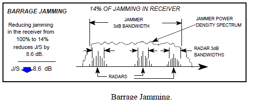
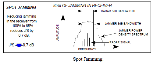
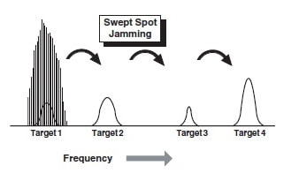
INTRODUCTION A radar noise jamming system is designed to generate a disturbance in a radar receiver to delay or deny target detection. Since thermal noise is always present in the radar receiver, noise jamming attempts to mask the presence of targets by substantially adding to this noise level. Radar noise jamming can be employed by support jamming assets or as a self-protection jamming technique. Radar noise jamming usually employs high-power jamming signals tuned to the frequency of the victim radar. RADAR NOISE JAMMING EFFECTIVENESS The effectiveness of radar noise jamming depends on numerous factors. These factors include the jamming-to-signaI (J/S) ratio, power density, the quality of the noise signal, and the polarization of the transmitted jamming signal. One of the most important factors that impacts the effectiveness of radar noise jamming is the J/S ratio .The power output of the noise jammer must be greater than the power in the target return, as measured at the output of the radar receiver. To achieve this level of jamming power, radar noise jammers usually generate high-power jamming signals. These high-power jamming signals can be introduced into the victim radar's main beam to deny range information and into the victim radar's sidelobes to deny azimuth information. Another factor which impacts the effectiveness of radar noise jamming is the power density. The power density of the noise jamming signal has a direct relation to the J/S ratio. If the noise jamming signal is centered on the frequency and bandwidth of the victim radar, the jamming signal has a high power density. The ability of a noise jammer to concentrate the jamming signal depends on the ability of the jammer to identify the exact frequency and bandwidth of the victim radar. If the generated noise jamming signal has to cover a wide bandwidth or frequency range, the power density at any one frequency is reduced. Radar systems that are frequency agile or that employ a wide bandwidth can reduce, or negate, the effectiveness of noise jamming by reducing the power density of the jamming signal. The quality of the noise jamming also determines its effectiveness. To effectively jam a radar receiver with noise, the jamming signal must emulate the thermal noise generated by the receiver. This ensures that the radar operator or automatic detection circuit cannot distinguish between the noise jamming and normal thermal noise. Thermal noise is referred to as white noise and has a uniform spectrum. All of the frequencies in the bandwidth of the receiver have the same spectrum and amplitude that varies based on Gaussian distribution. A Gaussian distribution is simply a bell-shaped distribution of amplitudes. In order to be effective, the jamming signal should exactly match the characteristics of the thermal noise signal of the victim radar receiver. Polarization of the noise jamming signal is another significant factor that impacts its effectiveness. As discussed in Chapter 2, if the polarization of the jamming signal does not match the antenna polarization of the victim radar, there is a significant power loss in the jamming signal. Noise jamming systems designed to counter multiple threat radars, with various polarizations, generally use a transmitting antenna with a 45° slant or use circular polarization. Most threat systems are horizontally or vertically polarized. This results in a 50% reduction in effective radiated power (ERP) for most threat systems. A more serious power loss, nearly 100%, in ERP occurs when the jamming antenna is orthogonally polarized with the victim antenna. The polarization of the noise jamming signal impacts the J/S ratio and the power density. in pic noise modulated jamming RADAR NOISE JAMMING GENERATION Noise jamming is produced by modulating an RF carrier wave with random amplitude or frequency changes, called noise, and retransmitting that wave at the victim radar's frequency. Since noise from numerous sources is always present and displayed on a radar scope, noise jamming adds to the problem of target detection. Reflected radar pulses from target aircraft are extremely weak. To detect these pulses, a radar receiver must be very sensitive and be able to amplify the weak target returns. Noise jamming takes advantage of this radar characteristic to delay or deny target detection. The simplest method of generating a high-power Gaussian noise jamming signal is to employ a highly amplified diode to generate a noise signal at the frequency of the victim radar. This signal is filtered and directly amplified to the maximum power that can be generated by the transmitter. This method is called direct noise amplification (DINA). The DINA method of noise generation has a serious limitation. The maximum power available from linear wideband power amplification is extremely limited. Employing any other form of power amplification would alter the Gaussian distribution of the jamming signal. This method of generating radar noise jamming was used extensively during WW II. Modern noise jamming systems generate noise jamming signals by frequency modulating a carrier wave at the frequency of the victim radar. FM noise jammers employ a receiving antenna to intercept the victim's radar signal. The antenna passes the victim radar signal to the receiver for identification. The receiver also tunes the jamming signal generator to the correct frequency. The receiver uses an automatic frequency control (AFC) circuit to tune the voltage controlled oscillator (VCO) to the frequency of the victim radar. A noise signal is generated by the jamming signal generator and added to the tuning voltage of the VCO to get an FM jamming signal. This signal is sent to a traveling wave tube (TWT) power transmitter. The TWT is normally operated in a saturated mode which produces a high-power jamming signal that covers a wider bandwidth than the victim radar. This reduces the power density of the signal, but the high power levels available from the TWT amplification of an FM signal compensate for this loss. The signal is sent to the transmitting antenna and directed toward the victim radar. An increasing of the noise will decrease the probability of detection and an increasing of the false alarm rate too. An important feature of a modern radar noise jamming system is, a look-through capability. A look-through mode allows the receiver to periodically sample the signal environment. The objective of the lookthrough mode is to allow the jammer to update victim radar parameters and change the jamming signal to respond to changes in the signal environment. This greatly enhances the effectiveness of noise jamming systems. One method used to provide a look-through capability is to isolate the transmit and receive antennas to allow continuous operation of the receiver to update signal parameters. Another method is to switch off the jammer for a brief period to allow the receiver to sample the signal environment. Since this latter look-through method eliminates the jamming signal, the amount of time the jammer is switched off must be kept to a minimum. BARRAGE JAMMING An important aspect of jamming power is power density. Noise jamming depends on power density for its effectiveness. Power density is a function of the frequency range, or bandwidth, of the jamming signal. If a jammer covers a narrow frequency range, it can concentrate energy in a narrow band. If a jammer covers a wide frequency range, the energy is spread over that entire range. Since the jammer has fixed radiated power, this lowers the effective jamming power at a given frequency. Barrage jamming is a jamming technique where high power is sacrificed for the continuous coverage of several radar frequencies. The jamming signal is spread over a wide frequency range, which lowers the ERP at any one frequency. This type of jamming is useful against frequency-agile radars, against a radar system that uses multiple beams, or against multiple radar systems operating in a specific frequency range. By spreading the jamming over a wide frequency range, there is some level of jamming no matter what frequency the radar uses. Barrage jamming was used extensively during World War II. Advantages of barrage jamming are its simplicity and ability to cover a wide portion of the electromagnetic spectrum. The primary disadvantage is the low power density, especially when a high J/S ratio is needed against modern radars. SPOT JAMMING One way to take advantage of the noise jammer's simplicity, but raise the jamming signal power, is to use a spot jammer. The earliest spot jammers were very narrow band jammers covering a bandwidth of 10 megahertz or less .This narrow band spot jammer was tuned to the anticipated frequency of the target radar. When it is necessary to jam a number of radars at different frequencies, more than one jammer is used. One problem that developed was of carrying the required number of spot jammers to counter a modern lADS. Also, radars that change their operating frequency, or are frequency-agile, defeat the spot jammer. Today, intercept panoramic receivers work with spot jammers to determine the frequency of the victim radar. A look-through capability is included in the system so that the target radar signal can be monitored to assess jamming effectiveness. The jamming signal can be adjusted for any changes in the operating frequency of the radar. The primary advantage of spot jamming is its power density. Radar or communications receivers can be countered at longer ranges than when using a barrage jammer of equal output power. A disadvantage of the spot jammer is its coverage of a narrow band of the frequency spectrum. An operator or computer in the receiver must constantly monitor and tune the jamming signal to the target radar's frequency. The complexity of this process increases when jamming frequency-agile radars that can change frequencies with every pulse. SWEPT-SPOT JAMMING When high power density is required over a large bandwidth, one solution is to take spot jamming and sweep it across a wide frequency range . This preserves the high power density but allows the jamming to cover a large bandwidth. The jamming spot is swept across a broad frequency range at varying speeds. With this technique, a number of radar systems can be covered. Because of their high jamming power, swept-spot jammers are able to cover a number of radars operating in a broad frequency range. However, jamming is not continuous. Fast swept-spot jamming can approximate continuous jamming by causing a phenomenon known as “ringing.” Fast sweeping spot noise is like a burst of energy which sets up vibrations within the receiver section. When these vibrations last until the next burst of energy is received, this is known as ringing. Three factors determine swept-spot jamming effectiveness. The first is the power in the spot. The next is the bandwidth, or frequency range, the spot covers. The last is the sweep rate. COVER PULSE JAMMING Cover pulse jamming is a modification of swept-spot jamming. This is a “smart noise” technique that is responsive for a short period of time . A repeater jammer acts as a transponder. It receives several radar pulses and determines the PRF (pulse repetition frequency) of the victim radar. It then uses this data to predict when the next radar pulse should arrive. Using an oscillator that is gated for a period of time based on predicted pulse arrival time, a noise-modulated signal is amplified and transmitted. This process works against a radar with a steady PRF, and allows a low-powered repeater to respond to a number of threats by time-sharing. Cover pulse jamming is used to initiate a range gate pull-off (RGPO) deception jamming technique. The deception jammer transmits a noise jamming signal, or cover pulse, which is much stronger than the target return. The cover pulse raises the automatic gain inside the range gate, and the range tracking loop initiates tracking on the cover pulse. The deception jammer then increases the time delay in the jamming pulse and moves the range tracking gate away from the real target. A form of cover pulse jamming is also used to initiate a velocity gate pulloff (VGPO) technique against continuous wave and pulse Doppler radars. The cover pulse, in this case, is a strong jamming signal with the same frequency shift as the aircraft return. This cover pulse steals the velocity tracking gate and sets up the velocity tracking loop to steal the velocity tracking gate based on false target Doppler shifts. MODULATED NOISE JAMMING
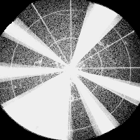
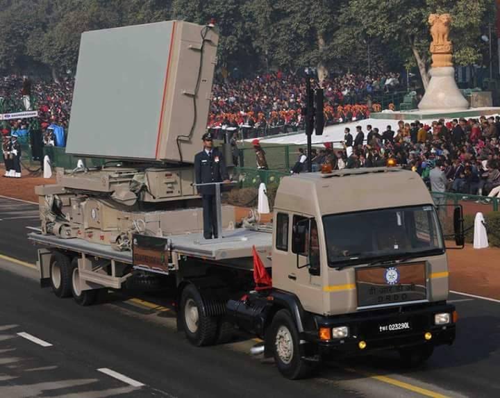
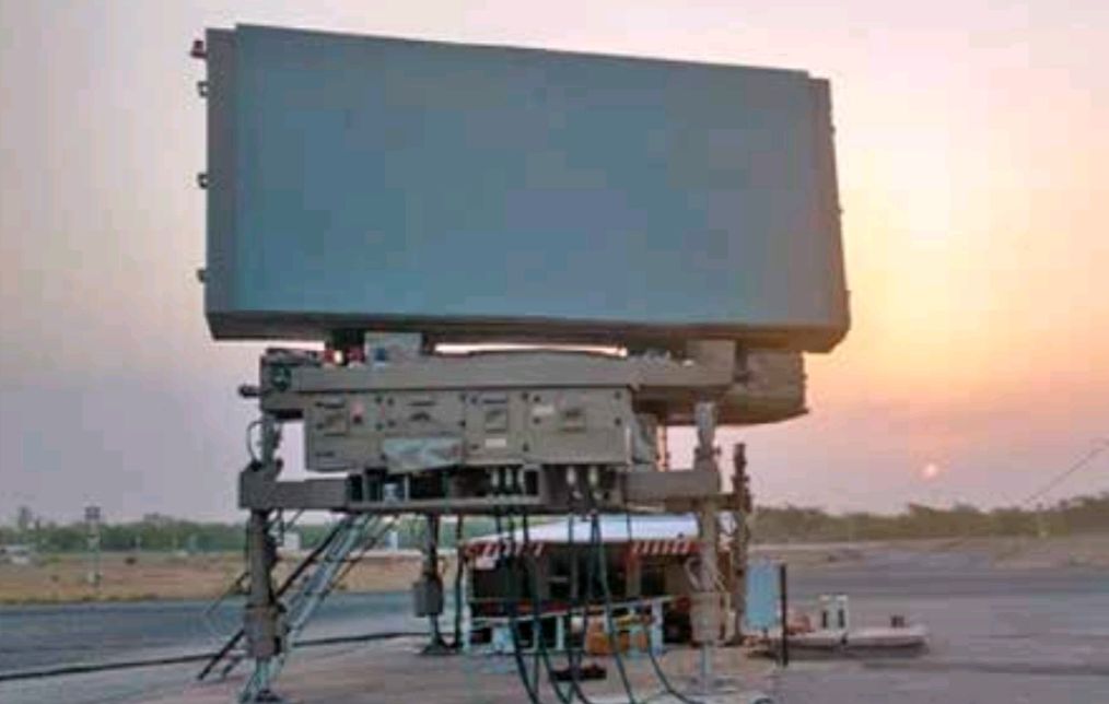
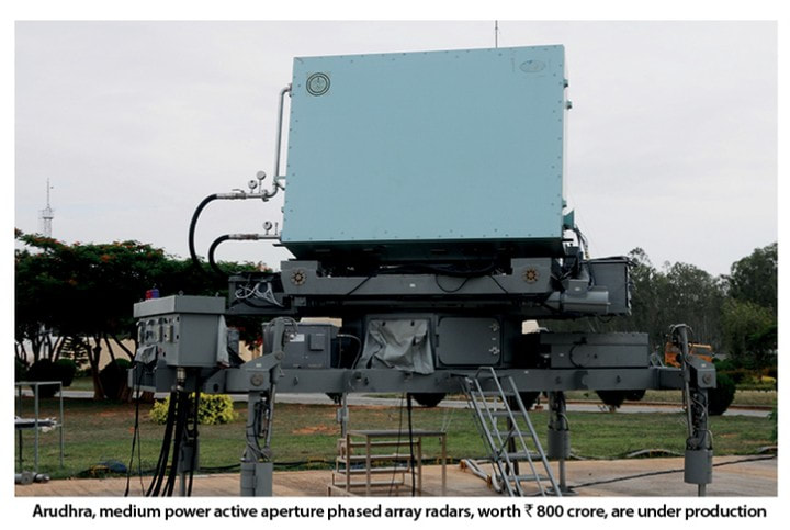
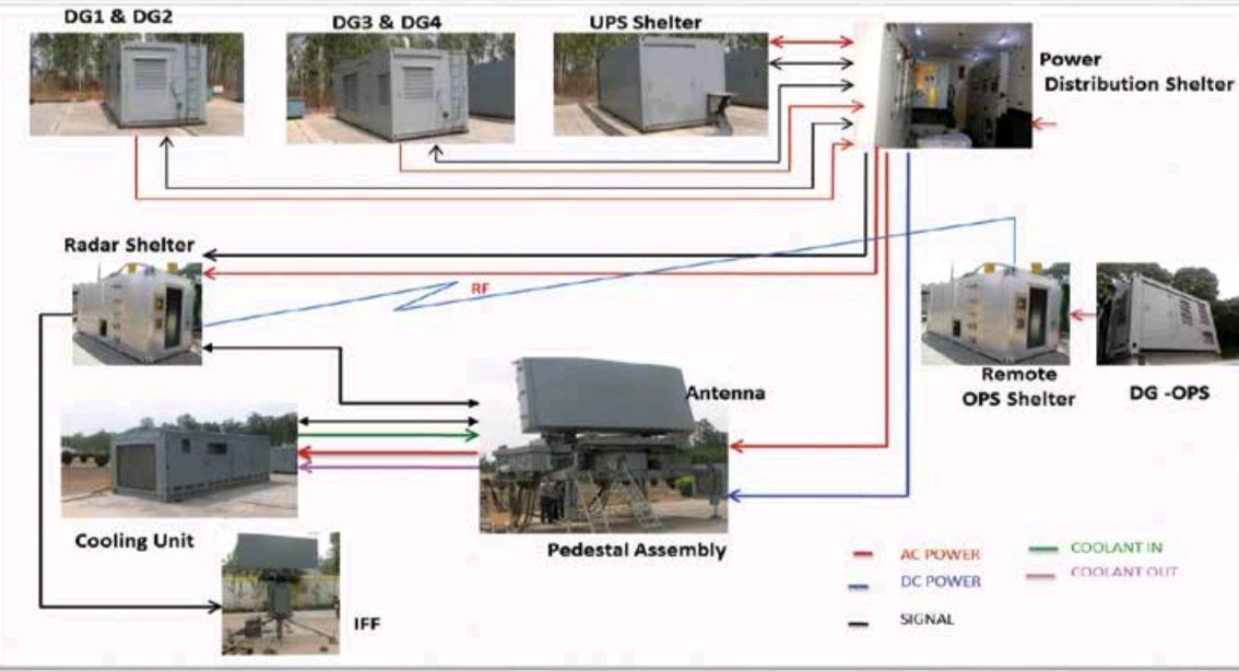
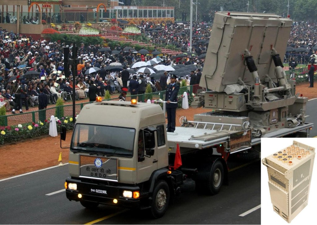
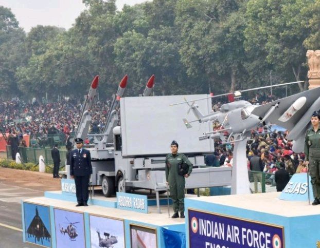
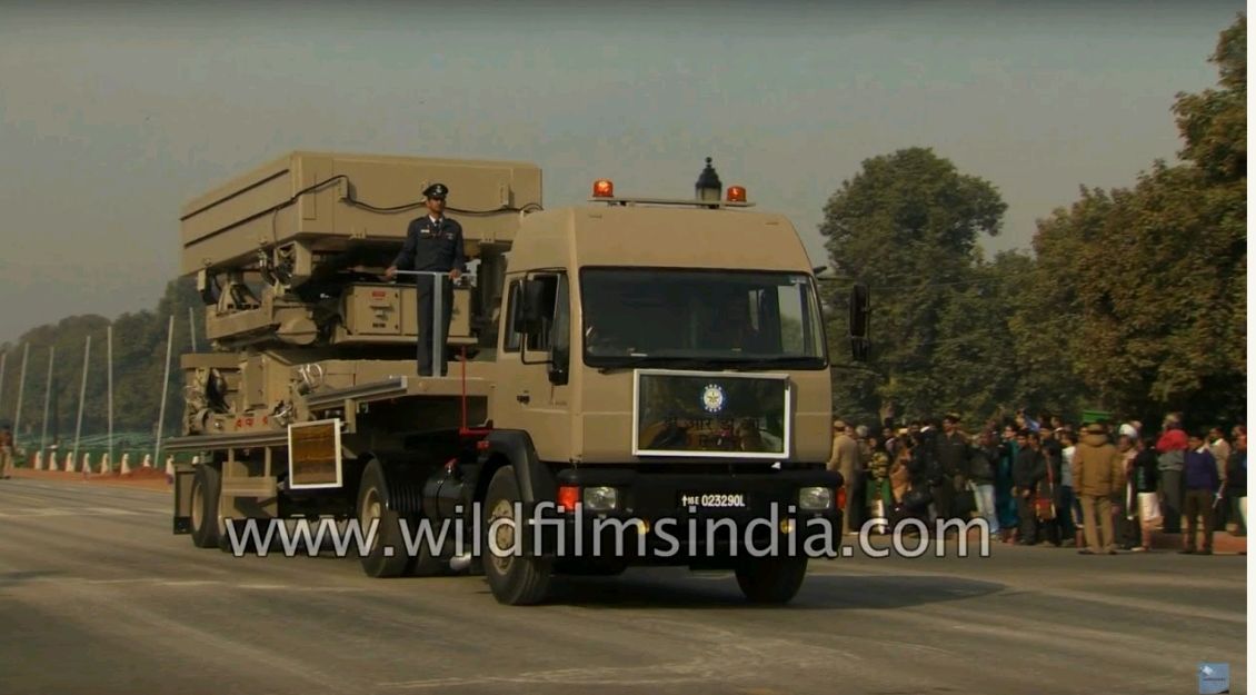
Modulated jammers are special hybrid jammers which employ noise jamming that is either amplitude or frequency modulated. The purpose of this modulated noise is to defeat target tracking radars (TTRs) rather than deny range information. Modulated noise jamming has proven effective against conical scan and trackwhile- scan (TWS) TTRs. Modulated jamming alters the noise jamming signal at a frequency that is related to the scan rate of the target radar. If modulated jamming is used against conical scan radar, a sine wave signal is used. The frequency of the sine wave is slightly higher than the scan rate of the victim radar. The amplitude difference results in a constantly varying phase between the radar and the jamming signal. This phase differential produces false targets with a strong signal amplitude everywhere the signals reinforce each other. This causes the conical scan radar to track the false returns and lose the real target return. For this technique to work, the scan rate of the intended victim radar must be known. Against TWS radar, a rectangular waveform is used to modulate the noise signal. The PRF of the modulation is set at some harmonic of the TWS rate. This synchronization results in a number of jamming strobes on the radar scope. Each jamming strobe is at a different azimuth or elevation depending on which radar beam is being jammed. The number of jamming strobes depends directly on the harmonic used to modulate the signal. In Figure, a modulating signal frequency that is four times the scan rate of the radar will produce four jamming strobes on the scope. If the jamming is slightly out of tune with the scan rate, the jamming strobes will appear to roll across the radar scope. SUMMARY Radar noise jamming is employed to deny target acquisition and target tracking data to victim radar. This is accomplished by injecting amplitude or frequency modulated noise jamming signals into the victim radar's receiver. The effectiveness of the above mentioned noise jamming techniques depends on the power density of the jamming signal compared to the power in the radar return, or the J/S ratio. Radar noise jammers are generally simple, high-power systems which can be effectively employed in a support or self-protection role. Radar noise jamming can be employed in conjunction with deception jamming techniques to maximize the impact of jamming on victim radars. With passage of time the adversary has grown stronger. If they want to, they won't directly launch a mass attack of ballistic missiles, but would rather use tactics, to saturate radar stations, employ jamming. Thus a need arises for unhindered surveillance of the airspace so that threat monitoring mechanisms can alert the respondents to quickly neutralise threats. The mission needs of Indian Air Force (IAF) is to have a gap free coverage for aerial threats from medium level height, 2 km, and above for a range up to 300 km. Until recently, these needs are met by PSM-33, P-40 and TRS-2215 kind of radars. However the service livesof these radars are over and any change in doctrine/tactics cannot overcome the void without any material solution. To overcome this void the Indian AirForce was in dire need of a next generational platform that can accurately detect the conditions of an alien object as well deal with any effort to neutralise the system. This led IAF to set up operational requirements keeping in mind newly available techs. The operational requirement was for the development of 4D rotating, phased array Medium Power Radar (MPR). The story of development of this advanced 4 Dimension radar is very interesting ,so is the technology involved. It is set to not just satisfy the security needs of IAF but also provide a and resistance to enemy tactics of creating any hindrance. Throughout the article we have provided carefully structured explanation of various terminologies involved in radar making as well as highly advanced technologies involved in this radar. Also provided a pinch of spicy history. INTRODUCTIONMedium Power Radar Arudhra is a 4D rotating phased array radar. It can automatically detect and track targets ranging from fighter aircrafts to ballistic missiles to slow moving targets. It can either be stable and stare or be rotated for 360° coverage. In rotation mode, the antenna rotates at 7.5 / 15 rpm with surveillance coverage of 360° in azimuth and 30° in elevation. In staring mode of operation the antenna stares in specified azimuth with surveillance coverage of ±60° in azimuth and 30° in elevation. Design, development and production of MPRs were categorized as ‘Make’ category. Electronics and Radar Development Establishment (LRDE), a Bengaluru-based DRDO establishment, took up the task and developed a fully engineered MPR for the IAF. The system has an instrumented range of 400 Km and is able to detect 2sqm RCS targets as far as 300 Km in range with the altitude coverage from 100 meters to 30 Kms. NOTE :- ‘Buy and Make’ means buying a portion of demand, obtaining ToT and production in India for remaining demand. ‘Make’ means developed by DRDO laboratories through indigenous efforts and manufactured by an Indian production agency. Medium Power Radar (MPR) is capable of automatic detection and tracking air intrusions at an altitude of about 100 meters up to a range of 30 km. IAF projected (November 2002) a requirement of 23 MPRs with active phased array radar technology for replacement [between X (2002-07) and XII (2012-17) Five Year Plan] of existing radars (PSM-33 radars, P-40 and TRS-2215 radars), which had completed their service life of 20 years.In active phased array each antenna has transmit / receive (T/R) modules to boost up output power of the transmitted signals required for maximum detection range. Based on Air HQ ORs (November 2004) and due to non-availability of technology, MoD approved (April 2006) import of 15 MPRs by IAF and indigenous development of eight MPRs by LRDE with a delivery schedule of 60 months (April 2011). LRDE submitted (November 2006) a proposal to Air HQ for development of MPR using imported antenna through direct import of MAP antenna from M/s Thales, France at a cost of `97.84crore to meet IAF time frame of 36 months. However, Air HQ insisted (June 2007) LRDE to develop a fully indigenous MPR including its antenna using latest technology. Accordingly, LRDE submitted (September 2007) revised proposal to develop active phased array technology based MPR with Digital Beam Forming (DBF) feature, Digital Beam Forming is employed to synthesize multiple signals received in the form of a beam, the Ministry sanctioned (November 2008) the project MPR ‘Arudhra’ under MM at a cost of `134.14 crore with a time frame of 54 months (May 2013) which was extended to October 2014. OPERATIONThe Arudhra is a 4D rotating antenna active phased array radar. It can also be stable and stare only in one direction. It uses cross pattern of five beams in azimuth and elevation is used for dedicated tracking of detected targets with good accuracy. What are these patterns? We know that AESA radars are made up of not one single antenna, but an array of multiple antennas. A radar needs to radiate waves in a single direction so that the waves strike target and get back making the antenna realise target location. But in reality it is impractical to make an antenna which is fully coherent and radiates all the waves in one direction only. An antenna even that of a radar radiates waves in all directions, but these antennas are designed in such a manner that maximum amount of waves are radiated in the desired direction. The radiation pattern of an antenna is dependent on it's shape. The pattern would be largely symmetrical to the shape of antenna. In an array of antennas the radiation coming from sides or undesired directions interferes at some angles and being out phase with each other they cancel each other out. If this is plot on a graph, the plot will show maxima at the desired direction. This Maxima is called a lobe and for an array of antennas their will be multiple lobes. Practically their will be lobes in all directions but the largest love would be in the desired direction, a direction where we intend to radiate waves. The larger the antenna is compared to a wavelength, the more lobes there will be. In a directive antenna in which the objective is to direct the radio waves in one particular direction, the lobe in that direction is larger than the others; this is called the "main lobe". Arudhra radar has a cross pattern of 5 beams in azimuth and elevation, means that 5 beams independently scan the surrounding airspace sideways and up and down ways to locate the target, one targets are located they are tracked while still more targets are searched. The coverage is attained using wide transmit beam and multiple receive beams in both azimuth and elevation. The system is able to survive intense ECM environment and possible electromagnetic interference. Arudhra is fully programmable from the local Operator Work Station and from remote Operator Work Station Unit. Arudhra being a 4D radar can determine range (straight distance from radar), azimuth (angular position from a reference direction), altitude (distance from ground) as well as velocity vector (representation of direction of motion) of a target. The Radar is based on solid state active aperture phased array with Digital Beam Forming and has electronic scanning capability in both azimuth and elevation. Digital Beamforming a certain number signals first pass through an analogue to digital converter to create equal number of data streams. Then these data streams are added up digitally, with appropriate scale-factors or phase-shifts, to get the composite signals.Digital beamforming has the advantage that the digital data streams (100 in this example) can be manipulated and combined in many possible ways in parallel, to get many different output signals in parallel. The signals from every direction can be measured simultaneously, and the signals can be integrated for a longer time when studying far-off objects and simultaneously integrated for a shorter time to study fast-moving close objects, and so on. Beamforming is achieved by combining elements in an antenna array in such a way that signals at particular angles experience constructive interference while others experience destructive interference. Beamforming can be used at both the transmitting and receiving ends in order to achieve spatial selectivity. The Arudhra is also capable of things like multi target tracking and target classification. While reconnaissance missions spy on enemy's assets they carefully record the 'reflector components’. The information about these reflector components is stored inside threat libraries of Arudhra as some picture of target already available. Then while normal operations the radar computer tries to match the reflector components of the target being tracked with the known reflector components (their are various techniques to do so) and calculate the probability of correct classification PCC if the PCC is high then the previously known designation of target is displayed on screen. NEW TECHNOLOGIESRotating Active Phased Array Rotating APARs are a new thing and an attractive alternative to having four arrays fixed at four directions. Many people who call Arudhra as a developed version of EL/M 2084 do not realise that the array of both hugely differ. Time synchronization of multiple receivers. Multiple receivers may not be receiving their own particular waves at a same time than each other. Their are variations in the amount of time needed for doing the entire operation of send and receive, synchronization problem consists of four parts: send time, access time, propagation time, and receive time. So when different receivers are observing the same thing but at different a different time which would be relativly true to their own self but may not match with other fellow receivers. To accurately determine location, proximity,speed of a target all the data received by different receivers must be synchronised with respect to time standard to all. The concept of time and time synchronization is needed in all such wireless devices. 2D Digital Beam-forming. We have seen what is beam forming in above text, in digital beamforming amplitude and phase variation is applied before digital to analogue conversion so that a desired wave can be formed through that particular T/R module. And after receiving the signals they are converted down to digital form and then summation is done. This is amazing and unlike analogue beamforming where received analogue signals are summed up and then converted from analogue to digital. This is why AESA radars can emit waves of multiple frequencies at a smart time. DBF based active array calibration. For digital beam forming the calibration of phase is necessary so that the entire beam could be coherent whenever needed. For this their are various procedures and protocols to calibrate and fine tune the active array, it is very difficult process and has been done in Arudhra at a big level. Multi-Beam processing. The processing of beams radiated and received by antenna array focuses on presentation of data on a 2D screen of that of a 3D airspace, classification and categorisation of threats etc. Critical real-time software and firmware. The real time computing guarantees the response within specified time constrained all the functions from start of scan to display of target must happen in real time, means their shouldn't be any delays for target detection Real-time responses are often understood to be in the order of milliseconds, and sometimes microseconds. If the response even taken more than one second it cannot be called real time. Development of such an advanced technology is a huge challenge overcome during AESA radar development. Independently rotating IFF radar. Usually the identification friend or foe IFF radar is integrated with main array itself. Friendly aircrafts are equipped radar transponder, that replies to each interrogation signal (sent by IFF radar) by transmitting a response containing encoded data. The encoded data is secretive and coded on friendlies so that radars like Arudhra interrogates the targets it is tracking and then classifies them into friend or foe. Mechanical Packaging (Engineering, Thermal, etc.,) Packaging focuses on mobility and quick deployment of Arudhra system. The system could be able to quickly pack and unpack so that it could be deployed in short notice. Thermal packaging is designed for temperature sensitive products that require a defined temperature to be maintained during transportation to the end user. Special thermally insulated packages need to be developed , tested, validated and produced for this purpose. All the necessary packaging systems were developed in-house by DRDO. INDUCTION INTO SERVICE.Arudhra is the first indigenous rotating Active Phase Array Multifunction 4D radar capable of employing state-of- the-art DBF technology with multi beam processing for the first time in India. Radar has undergone extensive user evaluation at various locations and has been accepted by IAF for induction and is ready for production. MPR technology can be to be used for any ship borne radar applications. The technology will be used for mountain radar and in future family of radars of LRDE for various application. Presently MPR technology is used for similar class of radars for Indian Army. Field trails of the radar in integrated mode have carried out successfully in various locations. Usually scientists are criticised for delaying stuff and the critics have no idea about what job they have to do, when they start it they can only assume the completion of time,but while doing an entirely new thing a person never knows for sure at what time it would get completed. Fullaftetburner has always focussed on presenting selected technical data that would be a treatise to the readers interested in defence, but endless bickering won't be tolerated. For image Sources click on respective images. Info Sources :- https://www.google.co.in/url?sa=t&source=web&rct=j&url=https://www.drdo.gov.in/drdo/English/mpr.pdf&ved=2ahUKEwii1aTMr5jaAhVGPY8KHZhsBnAQFjANegQIBBAB&usg=AOvVaw3c1vVNl2rJe8vmFTGeZPlt https://drdo.gov.in/drdo/pub/newsletter/2018/mar_18.pdf www.radartutorial.eu Wikipedia. We create top class content sparing time from our personal lives. It is difficult to make such content as it involves a lot of Background Research.We will continue to do so for a forseeable future as we are planning to buy our own website domain. It is absolutely important that we should remain financially strong to bring such content. We request readers to contribute some amount for our cause. |
AuthorPalash Choudhari Archives
June 2021
Categories
All
|

 RSS Feed
