|
XPoSat is a dedicated Indian polarimetry mission to study various dynamics of astronomical sources in extreme conditions. It works in medium energy band and long duration spectroscopic observation in soft energy X-ray band. The mission will help to understand the emission mechanism from a variety of X-ray sources. 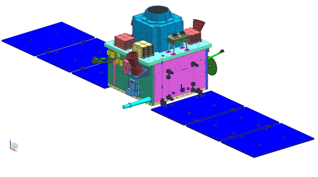 The spacecraft will carry two scientific payloads in a low earth orbit with preference for a low inclination orbit. The primary payload POLIX (Polarimeter Instrument in X-rays) will measure the polarimetry parameters (degree and angle of polarization) of astronomical sources in medium X-ray energy of 8-30 keV photons. The XSPECT (X-ray Spectroscopy and Timing) payload will give spectroscopic information of soft X-rays in the energy range of 0.8-15 keV. The spacecraft is planned to be launched in 2021 but due to Chinese Wuhan virus pandemic the launch may get delayed. XPOSAT will provide a service time of at least five years. The observatory will be placed in a circular low Earth orbit of 500 to 700 km. 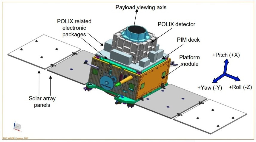 Deployed View of XpoSAT Introduction Since the birth of X-ray astronomy in early 1960s, there has been tremendous improvement in the sensitivity of the X-ray astronomical observations. As a result, three of the four dimensions of X-ray astronomy viz. photometry, imaging and spectroscopy are very well developed and fully mature subjects. However, the fourth dimension, namely polarimetry, so far has been almost untouched observationally. There has been only one measurement of polarization in X-ray astronomy, which was carried out for Crab nebula about 30 years ago. The OSO-8 satellite carrying an X-ray polarimeter was launched by NASA in 1976 which measured ~19% polarization at 2.6 keV and 5.2 keV for the Crab nebula. The only other polarimeter ever launched onboard satellite Arial-5 and few earlier rocket and balloon-borne experiments did not result in successful measurement. The main reason for the lack of X-ray polarization measurements so far is their extremely photon hungry nature that severely limits the sensitivity of the instruments. This coupled with the limitations of the measurement techniques resulted in almost three decade void in X-ray polarization measurements. Polarization is a very important property of radiation from astrophysical sources. It carries unique information regarding the emission mechanism, physical conditions as well as emission geometry at the origin. Polarization measurements in X-rays can provide unique opportunity to study the behavior of matter and radiation under extreme magnetic fields and extreme gravitational fields. Unfortunately, over past two decades, when X-ray astronomy witnessed multiple order of magnitude improvement in temporal, spatial and spectral sensitivities, there is no (or very little) progress in the field of polarization measurements of astrophysical X-rays. Recently, a proposal has been submitted to Indian Space Research Organization (ISRO) for a dedicated small satellite based experiment to carry out X-ray polarization measurement, which aims to provide the first X-ray polarization measurements since 1976. The X-ray polarization measurements are very important because they provide two independent parameters i.e. degree and angle of polarization to constrain the physical model for the X-ray source. Such measurements can provide unique opportunity to study the behavior of matter and radiation under extreme magnetic and gravitational fields. Prime targets for X-ray polarimetric observations are neutron stars (isolated neutron stars as well as neutron stars in binary systems) where the X-ray polarization measurements can provide direct information of the intensity and geometry of the magnetic field. Polarimetric observations of accreting Galactic Black Hole systems are also very interesting because they provide unique opportunity to test some of the predictions of general relativity which are inaccessible by any other means. Another set of interesting targets for polarization observations are the cosmic acceleration sites such as supernovae remnants and jets in Active Galactic Nuclei (AGN) or micro-quasars. Polarization observations of these sites will provide direct information about the geometry of the shocked sites as well as the structure and intensity of magnetic fields therein. The importance of X-ray polarimetric observations was realized for long time. There have been many reports on theoretical prediction of X-ray polarization from various types of X-ray sources even during early years of X-ray astronomy. Particularly in recent times, requirement of X-ray polarimetric observations has been strongly realized, mainly because, in various classes of X-ray sources, even the best spectroscopic or photometric observations cannot remove the degeneracy in the theoretical models. As a result, several groups worldwide have been attempting experiments which can provide the meaningful Xray polarimetric observations. X-ray polarization measurements can give valuable insights about
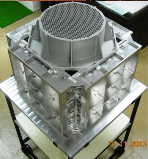
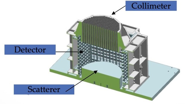
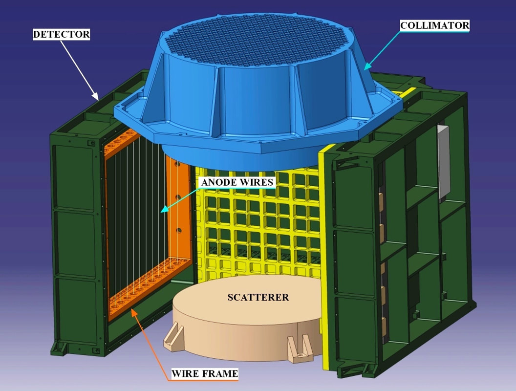 Configuration of POLIX POLIX The X-ray polarimeter (POLIX) is a scientific payload currently being built at Raman Research Institute to detect polarized X-rays from celestial sources. It is the only Thomson X-ray polarimeter currently being built worldwide and has an energy range of 5-30 keV. The instrument is designed, developed and tested at the Raman Research Institute POLIX is poised to be the first dedicated X-ray polarimeter mission in the world and to open a new window in high energy astrophysics by measuring X-ray polarization in about 50 bright X-ray sources, ahead of the NASA and ESA space mission proposals for launching X-ray polarimeters. The primary payload POLIX (Polarimeter Instrument in X-rays) will measure the polarimetry parameters (degree and angle of polarization) of astronomical sources in the medium X-ray energy of 5-30 keV photons. POLIX is a Thomson X-ray polarimeter for. The instrument consists of a collimator, a scatterer and a set proportional counters to detect the scattered X-rays. This instrument will provide unprecedented opportunity to measure X-ray polarisation in the medium energy range in a large number of sources of different classes with a minimum detectable linear polarisation degree of 2-3%. The prime objects for observation with this instrument are the X-ray bright accretion powered neutron stars, accreting black holes in different spectral states, rotation powered pulsars, magnetars, and active galactic nuclei. This instrument will be a bridge between the soft X-ray polarimeters and the Compton polarimeters. 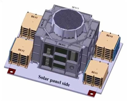 POLIX mechanical configuration including electronic package 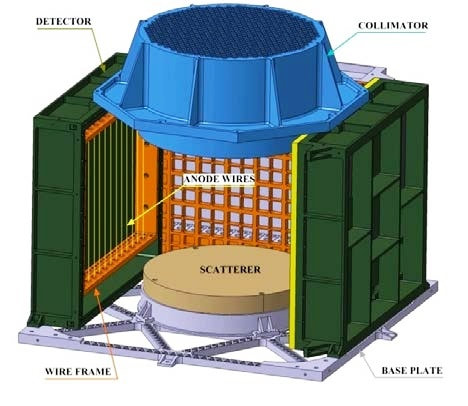 Principle of operation The instrument is based on anisotropic Thomson scattering of X-ray photons. X-rays from the source are made to undergo Thomson scattering and the intensity distribution of the scattered photons is measured as a function of azimuthal angle. Polarised X-rays will produce an azimuthal modulation in the count rate as opposed to uniform azimuthal distribution of count rate for unpolarised X-rays. 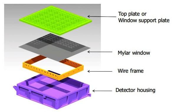 Structure of POLIX Detector Instrument Configuration The mechanical configuration of the polarimeter consists of X-ray detectors, placed on all sides of a scattering element. X-rays from cosmic sources are allowed to fall on this scatterer through a collimator which restricts the field of view of the instrument. The total configuration will be rotated about the viewing axis. In order to compensate for inaccuracy in satellite pointing and to attain constant effective area, a collimator with a flat topped response is required. To minimize the effect of photoelectric absorption of photons in the scattering element, a low atomic mass scatterer (lithium/beryllium) is preferred. POLIX consists of four independent detectors, each with its own front end and processing electronics. Localization of the X-ray photon in the detectors is carried out by the method of charge division in a set of resistive anode wires connected in series. The analog electronics of POLIX include high voltage generation and control for operation of the detectors, amplification of the charge pulses, threshold comparisons and digitization of the housekeeping parameters. Electronics Engineering Group of RRI has carried out the design and development of both the analog and digital electronics systems for this instrument, meeting stringent requirements of a typical space mission. EEG has developed in-house a complete electronics system for (i) detector operation, (ii) pulse processing and digitization, (iii) on-board data handling, (iv) housekeeping, and (v) control The digital electronics consists of anti-coincidence logic, digitation of the pulse amplitudes, data generation in multiple modes and combining of data from the four detectors.RRI- EEG has successfully developed a digital signal processing system for POLIX which is more complex than schemes used in other space experiments based on proportional counters. The telecommand and telemetry interface of the POLIX payload with the satellite bus is developed jointly with the Space Astronomy Group of ISRO. The POLIX detectors are designed and fabricated in collaboration with the MES and are wired and assembled in EEG. Each detector has about 400 wires of 25 and 50 micron diameters precisely wired and soldered onto a frame. EEG has developed expertise over several years, of making it reliable so that the large number of wires sustains satellite launch vibration and thermal cycling in space for several years 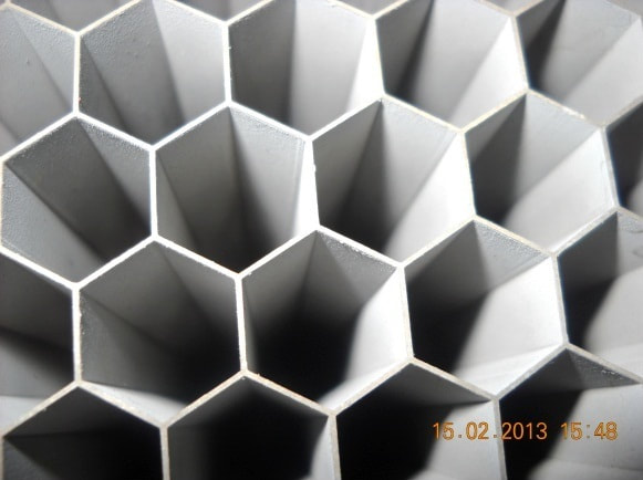 Collimator  Close-up view of Collimator Rationale for choosing polarimeter design based on Thomson scattering There are three basic techniques for measuring linear polarization of the X-ray photons, namely Bragg reflection, Thomson scattering and photo-electron imaging. Bragg reflection is one of the oldest and clean techniques to measure polarization of X-rays. Both the X-ray polarimeters flown to space so far (onboard Arial-5 and OSO-8) were of this type. However, the major drawback of this technique is that it works only at discrete energies. This results in very low sensitivity. Photo-electron tracking is the latest technique for measuring polarization of X-rays. Very high resolution position sensitive X-ray detector required to image the photo-electron tracks (a few hundred microns in a gaseous medium) are becoming available only recently and have not been used so far in any space experiment. The main disadvantage of this technique, particularly in the context of the present ISRO announcement of opportunity is that they have very small collecting area. Therefore these detectors must be used with the X-ray focusing optics. This combination might provide the best sensitivity for X-ray polarization measurement. However, it requires a full fledge X-ray astronomy mission which is out of scope for the present opportunity. Therefore, adopted a pragmatic approach to limit the sensitivity goal and use the well established technique of X-ray polarization measurement based on Thomson scattering. Though the most sensitive polarisation measurement devices are based on photoelectron track imaging, they require to be coupled with high throughput X-ray mirrors due to a small detector size. They also cover a softer energy range. The proposed scattering experiment is based on the well established technique of X-ray polarisation measurement using Thomson scattering which has moderate sensitivity over a relatively large bandwidth suited in the energy band of our interest. The experiment configuration consists of a central low Z (Lithium, Lithium Hydride or Beryllium) scatterer surrounded by xenon filled X-ray proportional counters as X-ray detectors which collects the scattered X-ray photons. The instrument is rotated along the viewing axis leading to the measurement of the the azimuthal distribution of the scattered X-ray photons which gives information on polarisation. The sensitivity of this experiment is dependent on a) collecting area b) scattering and detection efficiency c) detector background and d) modulation factor of the instrument. 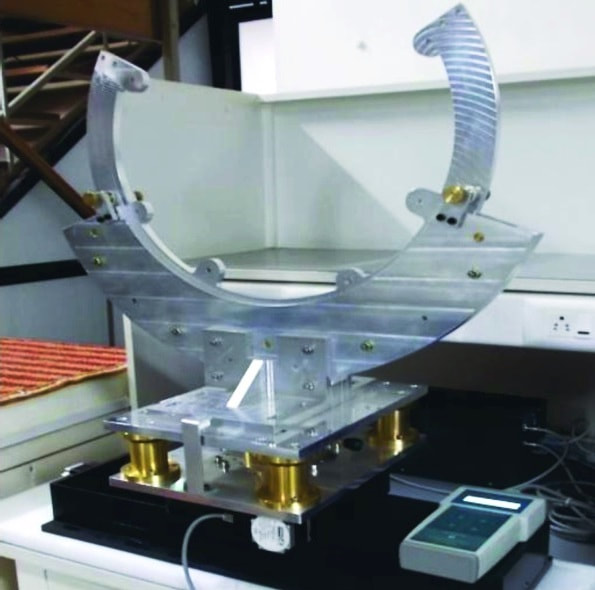 jig for calibration of collimator of the x-ray polarimeter Progress of POLIX during the years 2018
 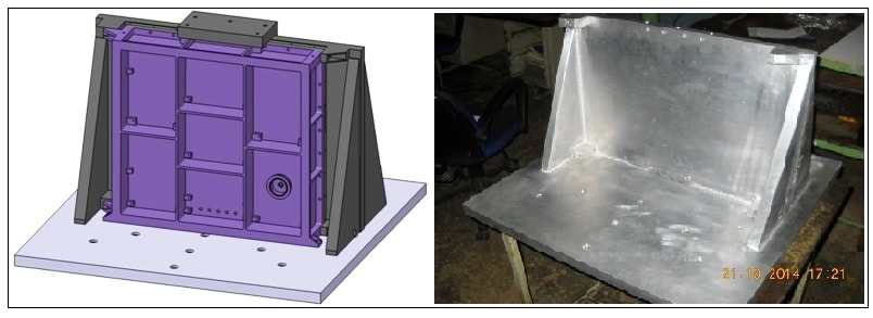 Detector of Polix 2019 During 2018-19, significant progress has been made in making the Qualification Model of POLIX and fabrication of some of the Flight Model components of POLIX has been initiated. The MOU between RRI and ISRO for POLIX was revised and second phase of funding for POLIX was released to initiate the Flight Model of POLIX.
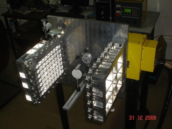 Engineering Model of POLIX detector at lab 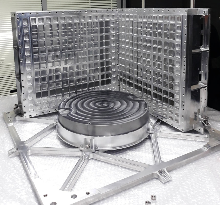 POLIX detector system 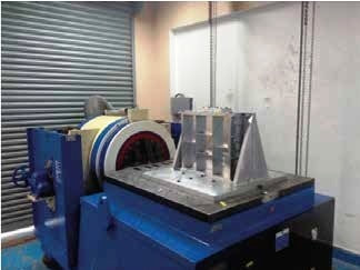 POLIX detector undergoing vibration test on mechanical shaker 2020 During 2019-20, significant progress has been made towards completion of the Qualification Model (QM) and Flight Model (FM) of POLIX.
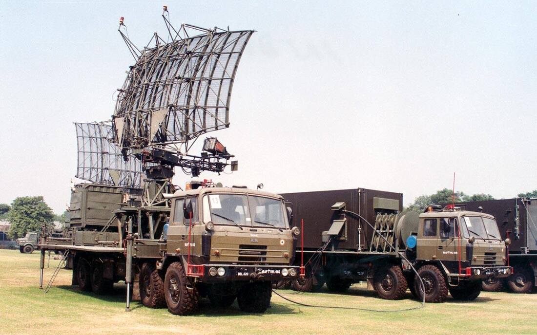
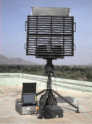
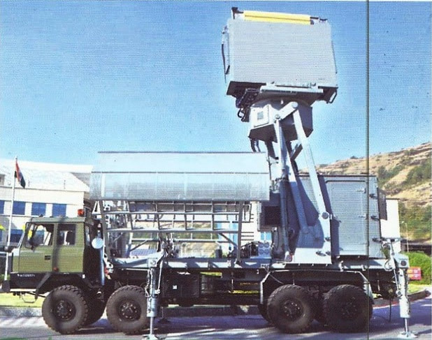
 POLIX payload detector inner view 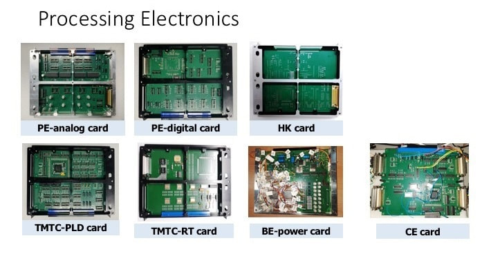 Processing electronics of XPOSAT XSPECT (X-ray Spectroscopy and Timing) The XSPECT (X-ray Spectroscopy and Timing) payload will give spectroscopic information of soft X-rays. X-ray Polarimeter Satellite mission carrying Polarimetry in X-rays (POLIX) and X-ray Spectroscopy and Timing (XSPECT) experiments with their viewing angles aligned with each other. In the aftermath of India's first multi-wavelength astronomy mission, a small payload (XSPECT) is proposed to address complementary timing and spectroscopy at low-energy X-rays. XSPECT provide unique opportunity to observe astrophysical sources for long durations to study their spectral and temporal variability in 0.8 to 15 keV X-ray band. The energy resolution of <200 eV @ 5.9keV and at -20°C and timing resolution of ~ 2 msec is planned. The proposed detector achieves modest effective area without the use of focusing optics using the new large area Swept Charge Devices (SCDs; CCD-236) which are a variant of X-ray CCDs. SCDs permit fast readouts (10-100 kHz) and moderately good spectral resolution at the cost of a position sensitivity. These devices are unique in requiring very benign cooling requirement (uses only passive cooling) unlike traditional X-ray CCDs. XSPECT with a passive collimator of 1 deg × 1 deg field-of-view, is ideally suited to pursue soft x-ray timing studies, complementary to what LAXPC does at high energies on ASTROSAT while simultaneously providing good resolution spectrum in the 1-20 keV band. Key science objectives include understanding long-term behavior of x-ray sources through correlation of timing characteristics with spectral state changes and emission line variations. Alongside x-ray polarimeter, this can provide a near-complete system to address photon energy, timing and polarization simultaneously. The instrument is under development and expected to be delivered in 2021. 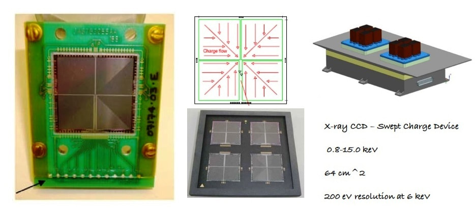 X-ray SPECtroscopy and Timing (XSPECT) Payload 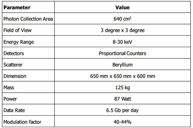 POLIX Specifications 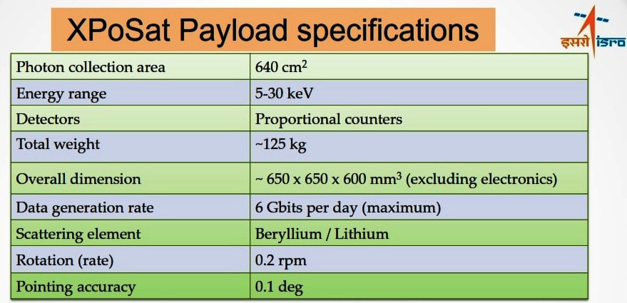 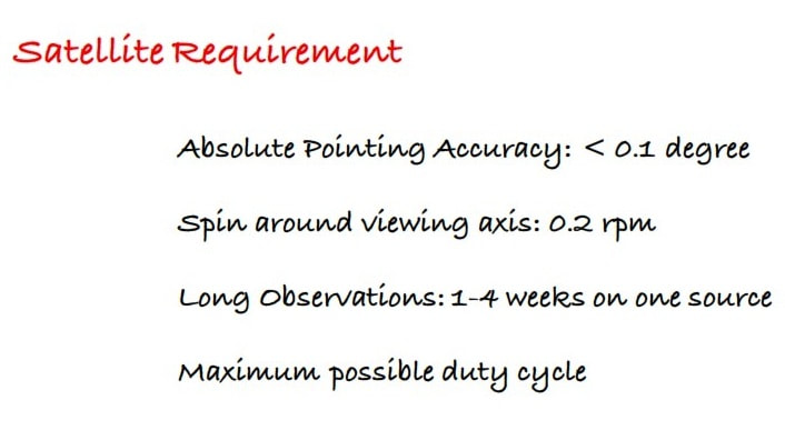 Satellite Requirement 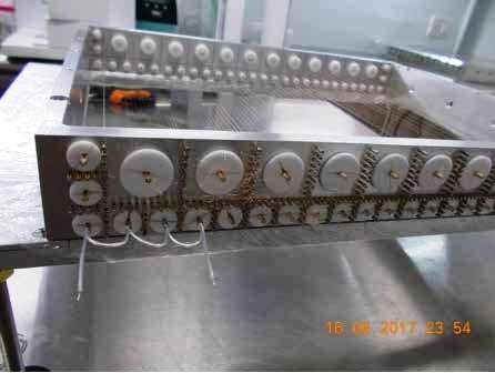 Proportional counter detector wiring 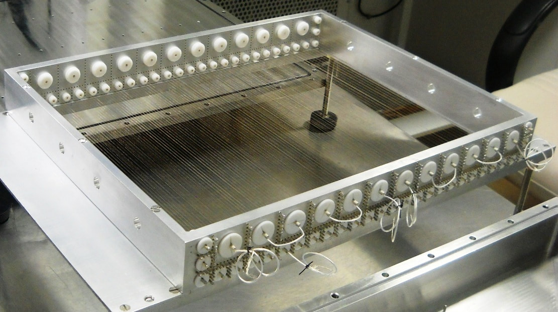 A fully wired wireframe 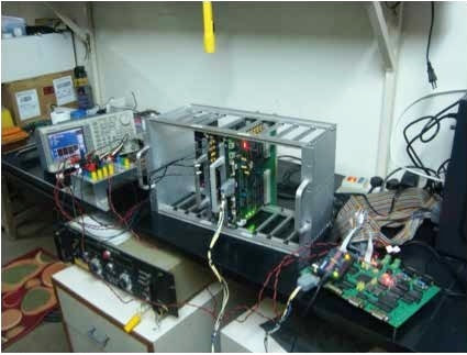 Pre-engineering model of POLIX signal processing electronics 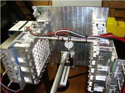 The rotary stage with the detectors mounted for testing 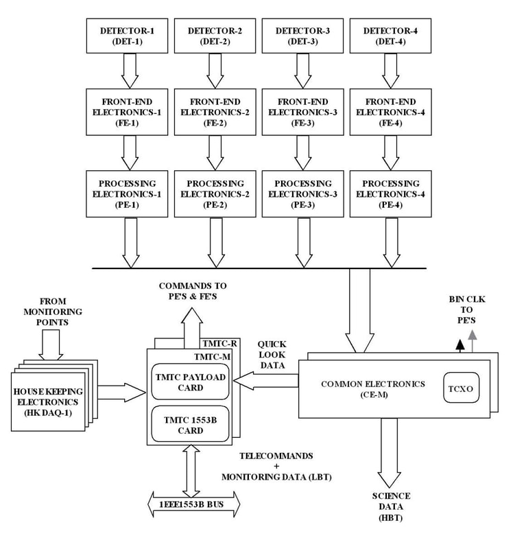 POLIX Electronics INDRA 1 The Indian Doppler Radar (INDRA) 2D radars were developed by India’s DRDO for the Army and Air Force. The INDRA-I is mobile surveillance radar for low level target detection. INDRA meets Air Defence requirements of the Air Force. It is transportable by Rail, Road and Air. The radar is housed in two wheeled vehicles. Indra is operating in it can deploy for point and area defense or as gap filler for the air defense, especially against aircraft threat at very low altitudes. Indra uses a mechanically scanning doubly curved reflector antenna. It has high gain with fairly low sidelobes. The radiating element is a corrugated horn which supports dual polarization. The radar has an integrated Friend or Foe in the main antenna. Indra 1 is a classical keyed on/off pulsed radar and is distributed on only two trucks. Indra II uses pulse compression and is distributed on three trucks. It is connected to an air defense network using computer systems via satellite, fiber optics and microwave links. INDRA is transportable by rail, road and air. DRDO, along with private sector Indian industry, has developed upgrade packages for the existing Indra-1 (GRL-600). At least 30 INDRA 1 upgraded. All these radars can now function as 3-D solid-state digital radars. 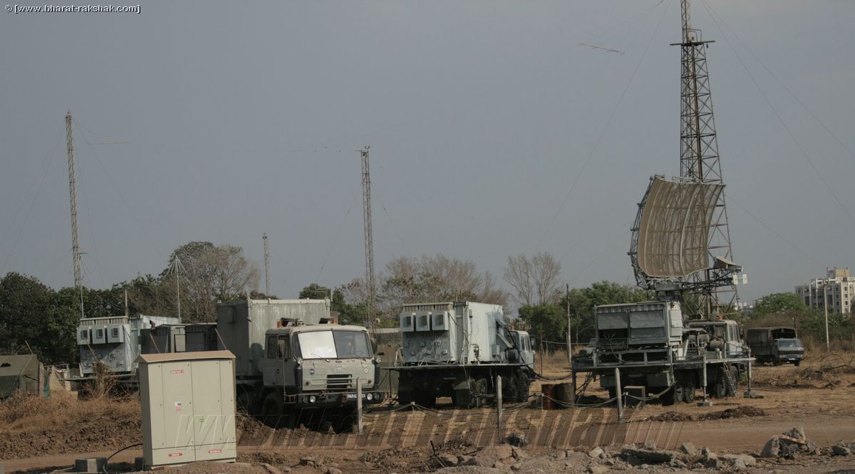 INDRA 2 It is a variant of INDRA radar for ground controlled interception of targets. INDRA II is L Band low-flying detection radar that caters to the vital gap filling role in an air defense environment. It is a transportable and self-contained system with easy mobility and deployment features. The system consists mainly of an Antenna, Transmitter cabin and Display cabin mounted on three separate vehicles. The radar uses pulse compression for detection of low flying aircraft in heavy ground clutter with high range resolution and ECCM capabilities. The system consists mainly of an Antenna, Transmitter cabin and Display cabin mounted on three separate vehicles. The radar uses pulse compression for detection of low flying aircraft in heavy ground clutter with high range resolution and ECCM capabilities. The radar has been produced by Bharat Electronics Limited and is used by Indian Air Force and Army. Seven INDRA-IIs have been ordered by the Indian Air Force. Features
System characteristics
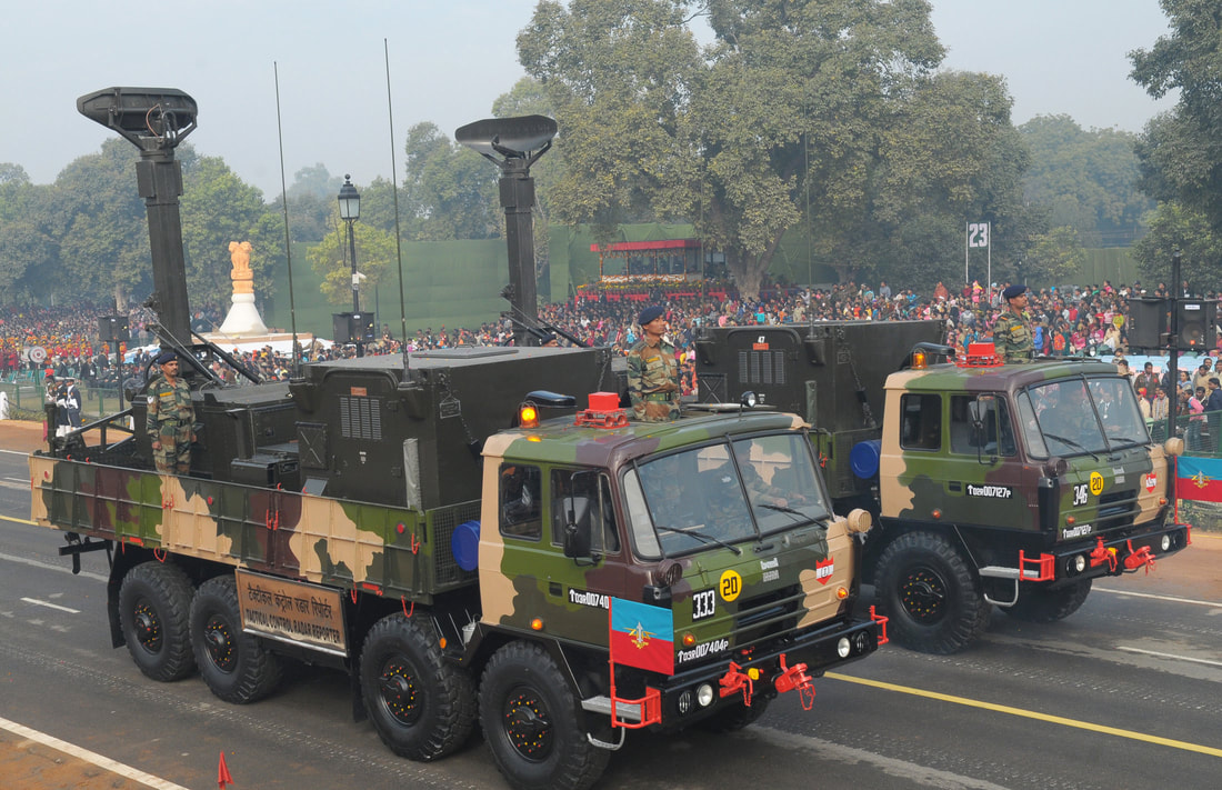
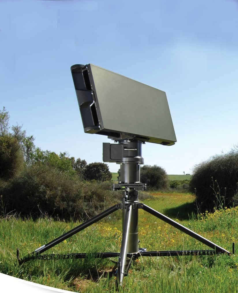
 Reporter Radar This is an early warning, alerting and cueing system, including weapon control functions. It is specially designed to be highly mobile and easily transportable, by air as well as on the ground. This radar minimizes mutual interference of tasks of both air defenders and friendly air space users. The command and control capabilities of the RADAR in combination with an effective ground based air Defense provide maximum operational effectiveness with a safe, efficient and flexible use of the airspace. Reporter radars are used as early warning system for Air Defense systems such as ZSU-23, L70 etc. Atulya Fire-Control-Radar will replace the Reporter radars. Features
 High Power Radar: THD-1955 India operates more than six High power THD 1955 3D long range surveillance Radars, can track targets nearly 1000 Kilometers, for stable and controlled watch IAF down powered the Radar to track targets upto some 400 kilometers. This radar, originally of French design, has been licence-built in India for a number of years. The radar has comprehensive ECM/ECCM capabilities and has no real detection altitude limitation. They are using E/F Band, though somewhat elderly, still has sterling performance characteristics. THD 1955 uses the S band for communication for faster refresh and data Transfer. The THD-1955 has a peak operating power of up to 20MW, though its normal operating power is usually 2MW. The Indian Air Force has undertaken to upgrade these radars with digital signal processing and clutter removal techniques. The ADGES communication system is also being updated by the digitalization of the analogue links and back-up satellite and fibre-optic communications. It also upgraded for improved survivability in dense EMP and Electronic Jamming. The upgrades were done by French firm Thales. THD 1955 are replaced / replacing by Medium Power Radars. 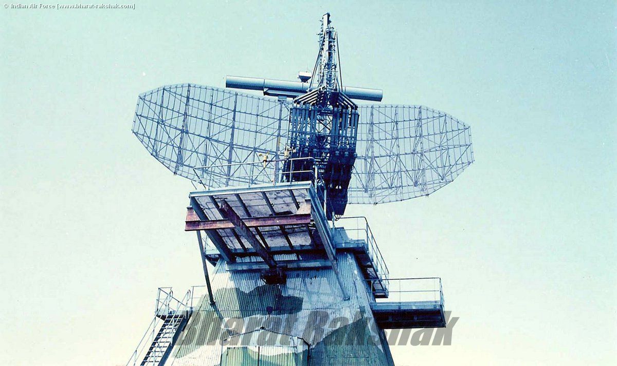 Flycatcher radar Flycatcher is weapon control radar for air defense fire control system for tanks, guns and missiles. It consists of two radars providing the acquisition and tracking element. The search antenna is of slotted waveguide type with a length of 1.5 m. It is deployed co-axially with the parabolic dish antenna in the Flycatcher system. The tracking radar antenna is situated center/front turret while the search radar antenna is mounted rear/top turret. Both antennas uses its own receiver. The transmitter of the search radar is operating in I-Band and uses a magnetron. In some versions this one transmitter provides also the tracking radar. In other versions the tracking radar uses its own transmitter operating in K-Band.TV tracking is an integral part of the Flycatcher system. This camera uses an optical zoom of 30 - 300 mm. Flycatcher has a range of 20Km. The Indian Defence Ministry floated a global RFP for the purchase of 66 Successor of Flycatcher and USFM radars in April 2008. In 2017 India inked the Rs 4,577 crore deal with Israeli Aerospace Industries for 66 fire control radars, with maintenance transfer of technology. This 3-D surveillance and tracking radars are intended to replace the aging Flycatcher radar systems present with the Army’s Air Defence Corps. However, the delivery was delayed because the Indian Ministry of Defense continued to pursue an even cheaper option for the program. As per tender norms, IAI will discharge 30 percent of the contract value as offsets to Indian companies. Most probably it was ELM-2026B which India selected to replace flycatcher. ELM 2026B is a highly accurate 3D Tactical Air Defense Radar that detects and tracks airborne targets, including: low RCS drones and UAVs, helicopters and fighter aircraft. The radar operates in X-Band and employs solid-state Active Electronically Scanning Array (AESA) technology. The radar is dual mode providing air surveillance and tracking with precise range, azimuth and elevation angles for anti-aircraft guns fire control. The radar employs multi-beam elevation coverage through Digital Beam Forming (DBF) and 360° azimuth coverage by antenna rotation. This radar is most probably part of ADFCR (See ADFCR & ELM 2026 B Section) India produced 120 flycatcher radar under license. 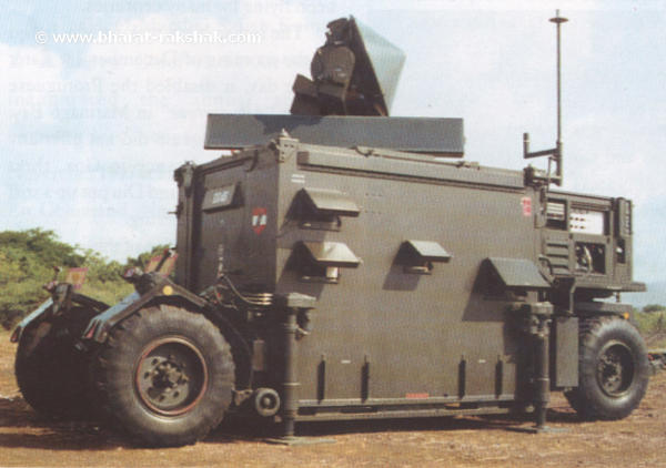 Super Fledermaus FCR The Super Fledermaus, is a pulse-radar fire control system which comprises a towed trailer, a Doppler radar in the E / F-band with a range of 15 kilometers and a pulse Doppler Rader in the J band, again with a 15 kilometer range. India used Super Fledermaus radar, in 35mm air defence batteries and designed to detect low-flying objects, such as unmanned air vehicles (UAVs). The digital system contains a built-in simulator as well as a signal jammer. The radar was acquired in the early 1980s and produced by BEL under license from the radar's designer, Ericsson Radar Electronics of Sweden. Upgraded by BEL in 2001(USFM-Upgraded Super Fledermaus), the Super Fledermaus now features highly capable tracking radar with significant capability against difficult, low-flying targets such as cruise missiles. The upgraded radar has a range of 56 miles (90 km) and is fitted with a new digital fire control computer. These systems were replaced /Replacing by Atulya Air Defense Fire Control Radar. 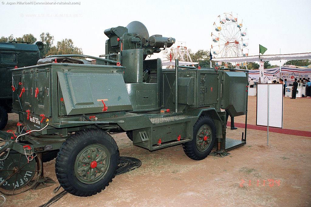 ADTCR ADTCR is the Army version of the Indian Air Force’s (IAF) Ashwini LLTR. It is a S band fully distributed active phased array radar mounted on a 8x8 HMV and is meant to be used for volumetric surveillance, detection, tracking and friend/foe identification of aerial targets of different types, and transmission of prioritized target data to multiple command posts/ weapon systems. It has fully automated surveillance and tracking capability. The radar is capable of detecting very small targets and low flying targets. The system employs Active Phased Array Technology with Digital Beam Forming, distributed Digital Receivers and IFF Mark XII. The Radar System, power and cooling systems, operator shelter, communication equipment etc is configured on 2 8x8 High Mobility Vehicles. The Radar can be deployed in plain lands, deserts and in the mountain regions for the purpose of tactical early warning for Ground based Weapon Systems. High altitude deployment at up to 4500m. It is road, rail and air transportable. Range : 90 km (1 m2) Altitude : 10 km No of tracks : 100  ADFCR (Atulya) Air Defense Fire Control Radar (ADFCR) in conjunction with Anti Aircraft Artillery forms a Ground Based Air Defense system whose main purpose is effective point defense against air threats at short and very short ranges during day and night under all weather conditions and in the presence of heavy enemy jamming (ECM). The system comprises of 1. X-Band Active Array Antenna based 3D Search Radar 2. Ka Band Tracking Radar 3. Electro Optical Sensors for passive 2D tracking and LRF for Radar independent ranging All the above and including the Gun Control Unit, Power Generator, and a suitably equipped Commander's cabin is mounted on a single High Mobility Vehicle. X band search radar Detection range 40 km for 1 m2 target, 20 km for 0.1 m2 targets, Altitude 30 m to 10 km. Ka band track radar Detection range 20 km for 1m2 targets, 10 km for 0.1 m2 targets. EO system: TV/TI camera 12/10 km for fighters/helicopters, LRF 12 km. The system is capable of controlling more than two AAA guns simultaneously. Operational altitude 10000 feet. The ADFCR is able to transmit data to MANPADs in a range of 8km over line and radio. The entire system is mounted on a single trailer in a modular configuration with its own captive power supply. The system can self-sustain for up to 8 hours. A NBC air-conditioned shelter is provided for the personnel as well as electronics. Key features:
 3D Surveillance Radar – Rohini Rohini is state-of-art radar designed to effectively play the role of medium range surveillance radar. It is mounted on a mobile platform. The radar operates in S-band. It can track targets up to a range more than 180 km and is capable of detecting low-altitude targets, and also supersonic aircraft flying at over Mach 3 speed, even under hostile EW operational environment. The radar scans the air space 360° in azimuth and 30° in elevation up to 18 km height. Rohini uses a passive phased-array antenna providing seven stacked pencil beams to discern the height of the target accurately. It consists of 32 rows of each 48 radiating elements distributed in four segments. On top of the primary radar antenna there is a Mode-S compatible IFF antenna. It is capable of handling multiple targets simultaneously and also precisely calculate the height at which projectiles are flying The radar features digital receiver, programmable signal processor providing high resolution, accuracy, response and information availability. The radar is packaged on two high mobility TATRA vehicles to meet operational and battlefield mobility requirements, one for the antenna and radar electronic (Radar Sensor Vehicle, RSV), one for a shelter containing the operator consoles (Data Center Vehicle, DCV) and supported by an auxiliary mobile power unit (125 kVA), it enables the Rohini to be easily transported to the battlefront. The radar can be deployed and decamped in less than 30 minutes. The radar employs an array of Electronic Counter Counter Measure (ECCM) features including frequency agility and jammer analysis. A Secondary Surveillance Radar, IFF, is integrated with the primary radar Rohini, which distinguishes friendly and hostile aircraft. During the course of development and trials of the ‘Rohini’, the IAF had placed two supply orders (in March 2006 and July 2009, respectively) with BEL for the manufacture and supply of 37 ‘Rohini’ 3-D CARs, while the Army has since ordered 14. About 100 Rohini radars are expected to be built, with around 20 radars being manufactured every year. Features
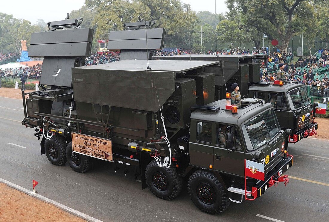
Variants Naval Variant : Revathy Air force Variant : Rohini 3D CAR : Akash Missile System 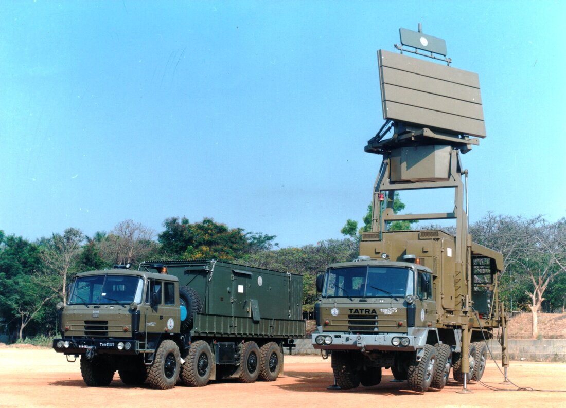 3D Tactical Control Radar (Indian Army) The 3D Tactical Control Radar is state-of-art medium range Surveillance & Tracking radar designed to effectively play the role of medium range surveillance radar mounted on a mobile platform. The radar operates in S-band 3D TCR is stand-alone and can operate in all weather conditions. 3D TCR can detect and identify various aerial targets, and can transmit pertinent data to Target Data Receiver. The Radar is capable of Track While Scan of airborne targets up to 90Kms, with advanced technologies like digital receiver, programmable signal processor providing high resolution, accuracy, response and information availability. Features
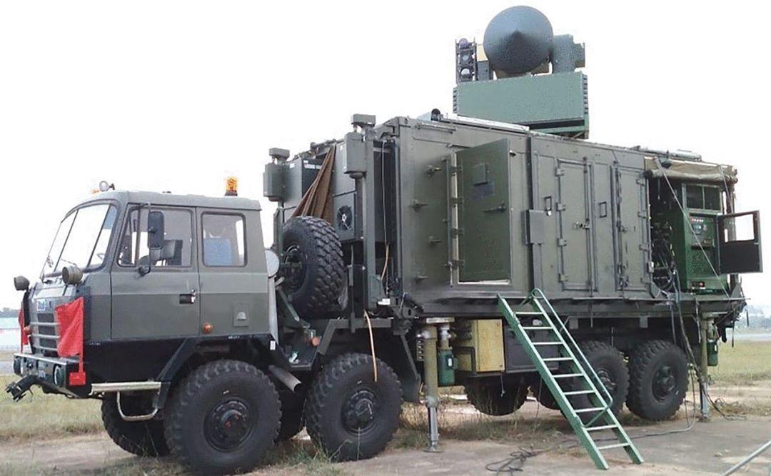
 EL/M-2084 MPR (Arudhra) IAF had imported EL/M-2084 MPR from Israel which is also known as Arudhra. ELM-2084 is ground-based mobile 3D AESA multi-mission radar (MMR). ELM 2084 featuring an advanced 3D Active Electronically Steered Array (AESA) for Air Defense (AD) and Artillery Weapon Location (WLR) missions. In the AD mode, the radar detects and classifies all types of airborne targets and generates a real-time Air Situation Picture (ASP). The WLR mode detects incoming mortars, artillery shells, and missiles and informs hostile weapon firing location as well as real-time calculation of impact point and friendly fire ranging. In addition, the Fire Control Radar (FCR) functionality enables control via uplink to anti-missile interception systems and Surface-to-Air (SAM) missile systems. ELM 2084 is mobile allows it can be transported quickly based on possible infiltration area's, such as Deep valley's blind zones,etc. India uses the Israeli made EL/M 2084 Multi mode radar, which is medium, powered which works as Surveillance but can Guide the Interceptor missiles to the detected Threat. 2084 can work with surface to air missiles like SpyDer , MR-SAM and Barak 8, can guide those missile if it detects and identified it's a Hostile threat. It can also be assigned to eliminate Ballistic missile too. ELM 2084 and Indian made Arudhra MPR replacing the older TRS-2215 and PSM-33 radars. These radars are more difficult to detect, jam or target with anti-radiation missiles. Detection range of up to 500 Km for Air Surveillance purposes or up to 100 km for Weapon Location purposes Azimuth coverage of 120° or rotating 360° for Air Surveillance purposes or 120° for Weapon Location purposes Elevation coverage of up to 50° & 100 kft for Air Surveillance purposes or up to 50° for Weapon Location purposes High accuracy 3D measurement for Air Surveillance purposes or 0.3% CEP for Weapon Location purposes Target capacity of up to 1100 targets for Air Surveillance purposes or 200 targets/min for Weapon Location purposes Features
Performance
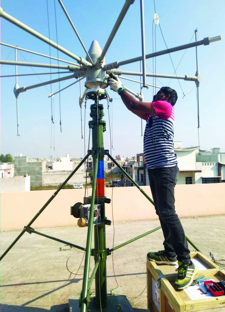
ELM-2248 MF-STAR: - is believed to be a variant of ELM 2084(need confirmation), made up of four MMR modules mounted around a pyramid shaped mast. The radar provides full 360º coverage for air surveillance, hostile weapons locating and fire guidance capabilities for naval platforms. The ELM-2248 is in service in the Israeli and Indian navies. The ELM-2248 is the fire control radar for the Barak 8 system. 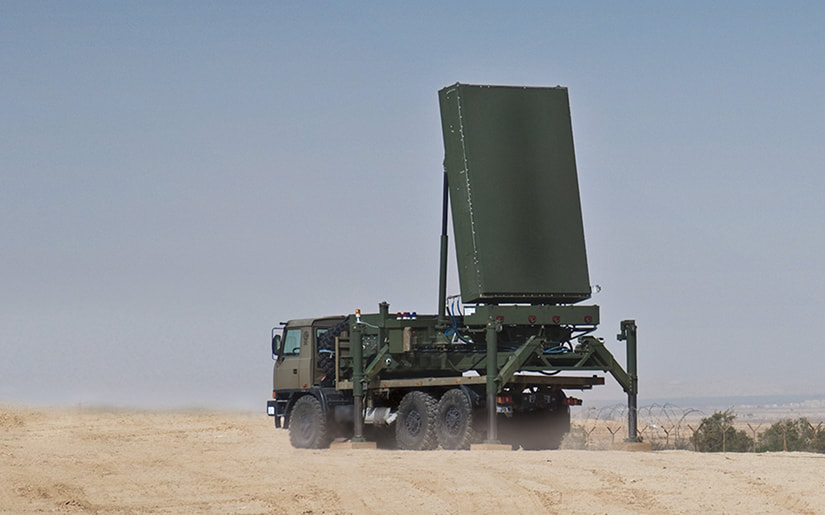 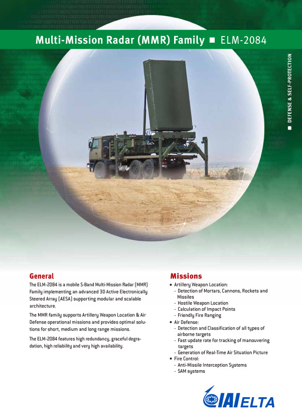 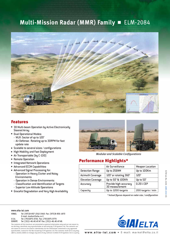 Medium Power Radar – Arudhra( Anirudha?) Arudhra, is a state-of-the-art radar, with 4D rotating phased array radar. It can automatically detect and track targets ranging from fighter aircrafts to ballistic missiles to slow moving targets. It can either be stable & stare or be rotated for 360° coverage. In rotation mode, the antenna rotates at 7.5 / 15 rpm with surveillance coverage of 360° in azimuth and 30° in elevation. In staring mode of operation the antenna stares in specified azimuth with surveillance coverage of ±60° in azimuth and 30° in elevation. The system has an instrumented range of 400 Km and is able to detect 2sqm RCS targets as far as 300 Km in range with the altitude coverage from 100 meters to 30 Kms. Arudhra will Replace the existing radars like PSM-33 radars, P-40 and TRS-2215 radars, which had completed their service life of 20 years. For More visit: - http://fullafterburner.weebly.com/next-gen-weapons/drdobel-arudhra-medium-power-radar-the-sacred-wave 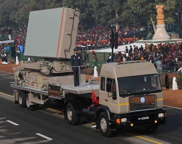 DRDO HIGH POWER RADAR (HPR) (Under Development) The HPR is Active Aperture Phased Array radar based on solid state Transrecieve Modules. It will have 4 large fixed radar panels and one rotating IFF antenna. Additionally necessary SATCOM and communication antennas will be installed to enable network centric operations. The Active Phased Array technology allows electronic scanning in azimuth as well as elevation. These radars have non-rotating design with planar arrays and provide 360 degree coverage without the requirement of mechanical rotation. There is seamless transition of tracks from one planar array to another planar array. The HPR is able to detect targets of 2m2 RCS at a distance of more than 450 km. The radar will classify targets automatically and it has organic ECCM features. It is able to resolve targets in four dimensions (4D) namely Range, Azimuth, Height and Doppler Velocity. The radar is equipped with ICAO & STANAG 4193 compliant IFF (interrogator friend or foe) system with provisions to operate independent of primary radar. The radar will be installed and integrated at high altitudes deployment sites. It is capable of being sited up to an altitude of 3000m Above Mean Sea Level. It can withstand severe environment conditions and will also be integrated to the IACCS Network of IAF. Sanction was given for initial 12 HPR radars in order to develop the same for providing long range, medium and high altitude cover while detecting and tracking low and high speed airborne targets. The radars will have the capability to scan 360 degrees without mechanical rotation of antenna and will operate on 24X7 basis with minimal maintenance requirements. These HPR radar site's will also have associated self defense systems both passive and active in order to combat threats from PGMs, LGBs, cruise missiles etc 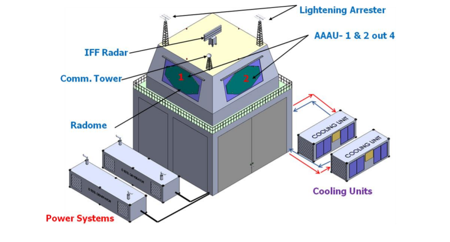 Low Level Light Weight Radars - LLLWR) These are gap fillers which provide coverage in difficult terrains where MPR might get masked. Bharani MK-1 LLWR 2D LLWR is a light weight battery powered compact sensor which provides 2D surveillance in mountainous terrain against hostile aerial targets like UAVs, RPVs, Helicopters and fixed wing aircraft flying at low and medium altitudes. It will act as an early warner to air defense weapon systems employed to provide protection to vulnerable areas or vulnerable points. The radar detects and tracks short-range with a high probability of detection. The radar has an integrated IFF that can detect confirm, classify and attain IFF status on every target in the battle space under surveillance. The radar has an integral GPS and it supports display tracks over tactical map overlay. Bharani can track up to 100 airborne targets. Bharanis meant to be used in conjunction with VSHORADS/MANPADS. Bharani are man-portable & can also be broken down into components for transportation by Yaks. Bharani can even be mounted on ATVs if needed. Features
Variants Army variant Air force Variant 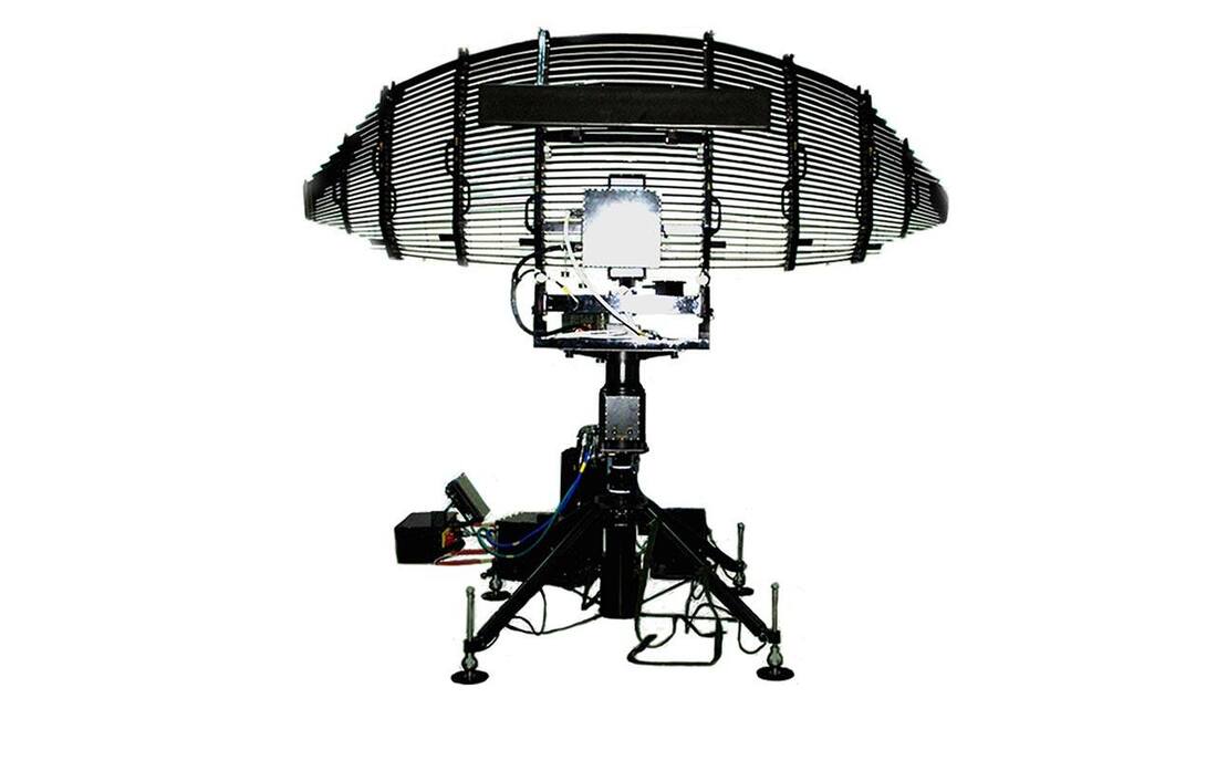 Bharani MK2 Bharani Mk.2 was envisaged as a 3-D surveillance radar with better low-altitude target detection capability and improved operational and performance characteristics. In April 2013 the Board of Directors of BEL approved a proposal to develop one prototype of Bharani Mk.2 having features similar to the IAF’s S-band Aslesha LLLWR, the Probable Date of Completion of design and development was October 2014. However, progress in the project was delayed due to finalization of the design by the LRDE and subsequently conducting the Preliminary Design Review with the end-user and BEL. In September 2016 LRDE designated design agency, had proposed Bharani Mk.2 using semi-active phased-array technology in L-band. Current status of MK2 is unknown 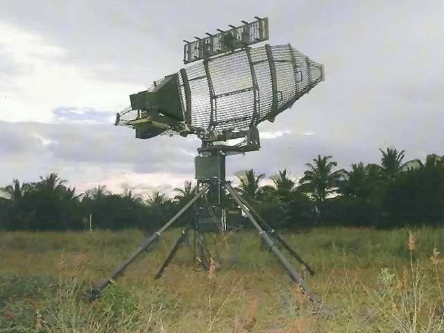 Aslesha Radar Low Level Light-Weight Radar (LLLWR) is an S-Band, 3D, light weight, battery powered and compact sensor which provides 3D surveillance. This radar is with multiple beams and electronic scanning capability in elevation and can be rapidly deployed in various terrains like mountain tops, deserts and even high rise buildings in urban areas to help carryout aerial surveillance at low and medium altitudes. The radar would provide for detection and tracking of all kinds of hostile aerial targets like fighter aircrafts, UAVs and helicopters. Aslesha, which weighs 250kg, uses low-probability-of-intercept frequencies to look out for terrain-hugging tactical UAVs over mountainous terrain out to 50km. This radar detects and tracks heterogeneous air targets including helicopters, fighters and UAVs at low & medium altitudes. This semi-distributed active aperture radar uses advanced VLSI and high-speed digital technologies like high efficiency TRMs, DDS, digital receiver and programmable signal processor to provide 3D air space awareness with high accuracy, resolution and reliability. Aslesha are man-portable & can also be broken down into components for transportation by Yaks. Aslesha can even be mounted on ATVs if needed. Features
 Aslesha MK2 Aslesha MK2 is an upgraded version of Aslesha Mk1. We believe development of Aslesha MK2 was completed. Most probably this radar has AESA technology. Details of this radar are not publically available. 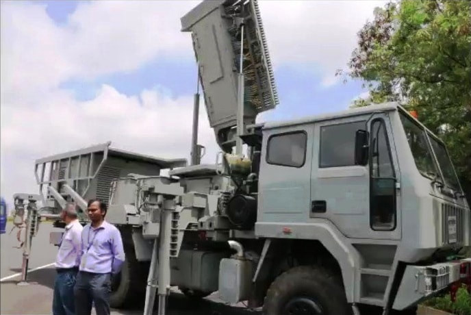 EL/M-2026B India Acquired 36 EL/M 2026B LLLWR from Israel. ELTA-supplied 15 EL/M-2026B X-band LLLWRs, balance 21 being acquired through indigenous development by the LRDE. ELM-2026B is designed for detection and tracking of airborne targets, including a wide variety of low RCS and low flying targets such as fighter aircraft, ultra-lights and UAVs. It employs fifth generation of 3D Tactical Air Defense Radars featuring a lightweight transportable, X-Band, pulse-Doppler solid-state electronically scanned array. The radar also employs multi-beam elevation coverage through Digital Beam Forming (DBF) and 360° azimuth coverage by antenna rotation, providing accurate target measurements of velocity, range, azimuth and elevation angles target detection and tracking and support of surface-to-air missile weapon systems. The ELM-2026B can be deployed as a local Air Defense system providing early warning and target track to surface-to-air weapon systems. Installation of the radar can be either fixed on the ground or tower, or transportable on a vehicle. Specifications Instrumental detection range: 25 km Detection range (fighter aircraft): 15 km Detected target velocity: 0 - 600 m/sec Update Rate: 2 sec (30 rpm) Range accuracy: 30 m Azimuth accuracy: 0.3° Elevation accuracy: 0.5° Elevation coverage: 60° Azimuth coverage: 360° No. of tracked targets: 100 by TWS Resolution:
Weight (antenna + pedestal): 75 kg (approx.) Power consumption: 500 W (approx.) Operating voltage: 28 Vdc (nominal) Features
 GS-100 LLTRs Indian Air Force (IAF) ordered 19 GS-100 Radars from Thales. Six of the 19 radars built at its Limours facility, southwest of Paris, the remaining 13 units Built by BEL in India. GS 100 (Ground Smarter 100) is operating in S-Band, mobile, modular and multifunctional sensor designed to track complex target manoeuvres at very low altitudes. It can be used as gap filler in very difficult terrain. Each low level transportable radar system comprises the GS 100 radar, operational and communications shelters, an energy subsystem, mobility subsystem and quarters for personnel. The radars gave the Indian military the capability to spy up to 60 km into enemy airspace and are ideal for detecting intrusions over mountainous terrain. It offers operational performance out to 180 km. GS 100 radar is using Gallium Nitride based T/R modules. Gallium Nitride based T/R modules are smaller, lighter and consume less power compared to the alternatives. 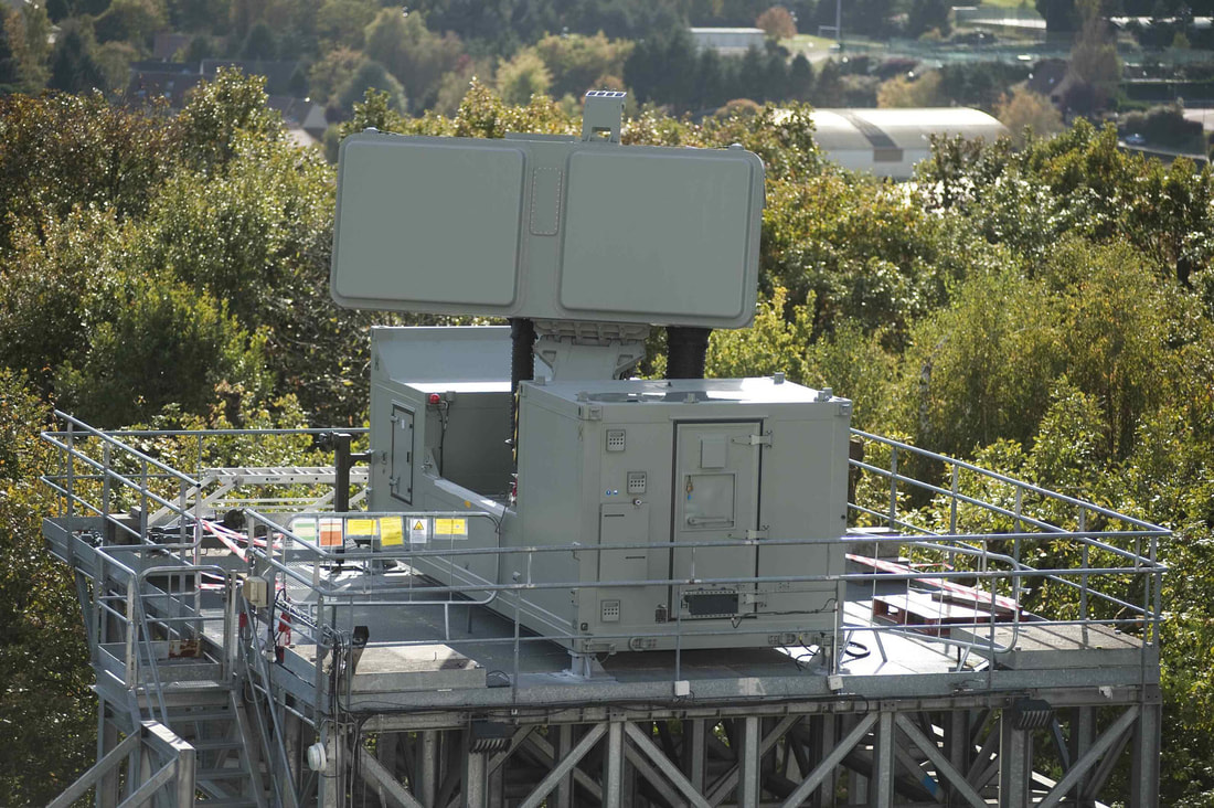 LLTR Ashwini The Indian Air Force (IAF) Ashwini is a Low Level Transportable Radar (LLTR) is a 4D, active array technology, multifunctional radar being developed to pinpoint with outstanding accuracy for highly maneuverable targets. It can work even under hostile EW operational environments. Ashwini LLTR is capable of automatic detection and tracking of aerial targets ranging from fighter aircrafts to slow moving targets. In addition to the range, azimuth and height, the new radar provides the velocity vector of the incoming target (4D). The system has an instrumented range of 200 Km and is able to detect 2sqm RCS targets as far as 200 Km, 0.2sqm RCS targets as far as 50Km in range with the altitude coverage from 30 meters to 15Kms. The radar operates either in Staring or Rotation Mode. In rotation mode, the antenna rotates at 7.5 / 15 rpm with surveillance coverage of 360o in azimuth and 40o in elevation. In staring mode of operation the antenna stares in specified azimuth with surveillance coverage of ±60o in azimuth and 40o in elevation. The Radar is based on solid state active aperture phased array with Digital Beam Forming and has electronic scanning capability in both azimuth and elevation. The coverage is attained using wide transmit beam and multiple receive beams in both azimuth and elevation. The following are the technologies established as part of ASHWINI radar and it has spin-off for all future similar class of radar projects of LRDE.
 ST-68 'Tin Shield' The ST-68/U is known by NATO as the Tin Shield radar and has a maximum range of some 217 miles (350km). It is optimised for the detection of low-flying aircraft and cruise missiles employing electronic countermeasures (ECM). This radar station is a true 3 D-radar with a frequency scanning array. The ST-68 'Tin Shield' Radar equips mobile 'TRU's or Transportable Radar Units in the Indian Air Force. The ST-68/U has a maximum range of some 350 km with a peak power output of 1.23MW, operating in the S/E/F bands. it can be deployed or stowed in one hour, or two with the mast. The design uses a large paraboloid cylindrical section primary reflector and a linear element array deployed on a pair of booms to provide electronic beam steering in elevation from -20 to +30 degrees, the antenna can perform a full 360 degree sweep in 5 to 10 seconds. With a transmitter peak power rating cited between 1.23 MegaWatts and 350 kiloWatts, the manufacturer claims the ability to detect a 0.1 square metre RCS target at 300 ft above ground level out to 46 Km, and at medium to high altitudes to 175Km. Clutter rejection is claimed to exceed 48 dB, and the system can track 100 targets. An IFF system is integrated in the radar. Some of these radars are upgraded but details not Known. 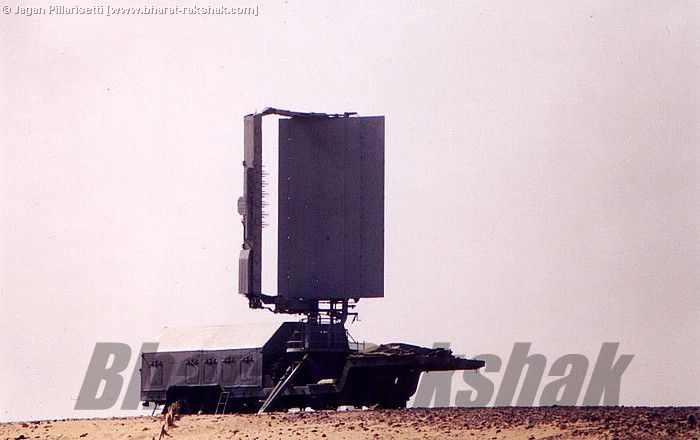 P-40 Radar (MI) One Signal Unit of the IAF still operates the 1963 vintage P-40(MI) Radar. This is tracked vehicle mounted 3D radar used for interception. TRS-2215D TRS 2215D is E/F-Band air defence 3-D radars, employing electronic phase scanning in elevation. The primary radar antenna is a direct radiation array of stacked linear subarrays fed by two vertical distributors used to form the sum and the elevation difference channels. Each linear subarray contains elementary sources radiating a circularly polarised wave. The two waveguides low monopulse operation to perform the height-finding function. Digital electronic phase shift networks inserted between the elementary feeds and the corresponding directive couplers control the pointing of the beams. The transmitter is an amplifying chain transmitter using a crossed field amplifier as its final tube. It permits the use of the pulse compression technique and that of pulse-to-pulse frequency agility. TRS 2215D has a Range of 510km. PSM-33 MK2 India has been producing the French-designed TRS-2215D 3-D surveillance radar under license for a number of years and has derived from that indigenously built radar - PSM-33 Mk 2. The TRS-2215D and PSM-33 Mk.2 have surveillance ranges of up to 510km with a peak power output of 660-700kW operating in the E/F bands and possess a very significant ECCM capability. Arudhra medium-power radar (MPR) replacing/replaced ageing TRS-2215 and PSM-33 radars on the inventory of IAF. 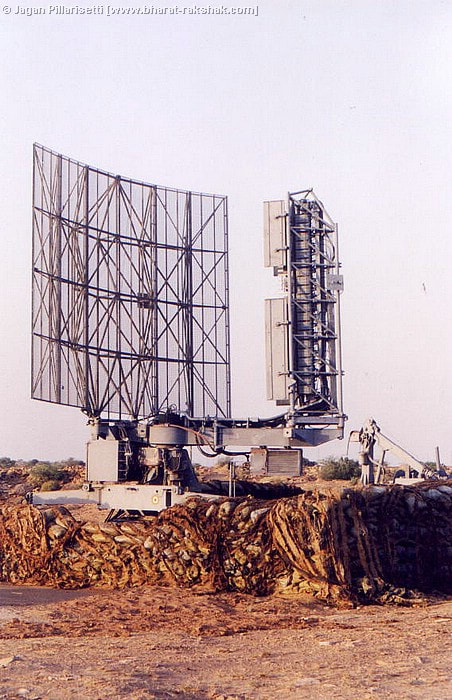 PSM 33 Passive Radar BEL in joint venture with Thales France developed and successfully demonstrated. Indian Air force installed these radars (Details and Numbers not Known). In addition to the Indian Air Force, the company is pursuing opportunities with prospective customers such as Cabinet Secretariat National Technical Research Organization etc. Passive Radar uses transmitters of opportunity from commercial broadcasting to detect and track aerial targets in real time, as this radar technology does not emit any electromagnetic transmission hence completely undetectable. This is FM based Passive radar. Features
Key Features
 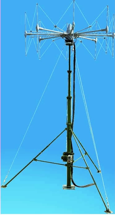 Long Range Radars India developed and deployed several long range radars. Information about these radars almost nill. Sword Fish Radar (LRTR) Swordfish is an Indian Long range tracking radar specifically developed to counter ballistic missile threat. It is a part of India’s ballistic missile program. Swordfish is a derivative of the Israeli Green Pine long range radar. However, it differs from the Israeli system as it employs Indian Transmit Receive modules; signal processing, computers and power supplies. It is also more powerful than the base Green Pine system and was developed to meet India’s specific BMD needs. India had acquired and deployed two Green Pine radars around July 2002 and another one in August 2005. Swordfish is a Target acquisition and fire control radar for the BMD system which is able to track and detect missile launches 600-800 km from its radar site. It was installed near Indian borders.  GreenPine Radar LRTR-2 LRTR-2 is an upgraded variant of LRTR and its come under the aegis of IAF. Long Range Tracking Radar can detect 0.1 m RCS targets at 1500 Km. A typical warhead of Chinese DF 17 has an RCS of 0.6m2(Calculated using Software’s) that means LRTR can easily detect and can intercept any Chinese SRBM , MRBM warheads. At least two LRTR-2 Radar systems have successfully been tested in real-world conditions where LRTR has initiated successful auto launches of Interceptor missiles towards its target. The land is been identified in the Eastern sector for the Radar deployment as well so Ballistic Missile Defense can extend coverage to both sides for possible coordinated and simultaneous missile attacks. Some experts believes , with long wavelength LRTR-2 can spot the re-entry vehicles as they rise above the horizon (while they are still 5,000km or six minutes away) and provide range, velocity and angular discrimination of the targets(Need Confirmation). LRTR-3 LRTR-3 is further upgraded version of LRTR-2. LRTR 3 has 2500+km range. Very Long Range Tracking Radar (VLRTR) VLRTR is the successor of LRTR series of radars. Very Long Range Tracking Radar VLRTR has a range of more than 3000 KM. Very Long Range Tracking Radar may be Using GaN based TRMs. VLRTR is used for Missile Monitoring System for detection of space borne threats in aid of Ballistic Missile Defence. The first Very Long Range Tracking Radar (VLRTR) became operational in 2017 following government approving induction of two new units of VLRTR under MoU between NTRO and IAF for realizing Missile Monitoring System to detect space-borne threats in aid of Ballistic Missile Defence (BMD). May be LRTR-3 and VLRTR are same thing, may be different versions which we can’t confirm now. Over The Horizon Radar DRDO working on over-the-horizon radar but the details are not known. BEL and Thales working jointly on over the horizon radar. According to unconfirmed reports India also operating over the horizon radar acquired from foreign country. Indian navy want its own OTHR facility as part of its project Varsha.  Ground Based Long Range Early Warning Radar Few years back in an interview DRDO chairman said about development of very large radar which probably have more than 100 meters length, probably it would be the Ground Based Long Range Early Warning Radar similar to US & Chinese early warning radars. We are not sure about the development of Ground Based Long Range Early Warning Radar may be it’s just a wrong assumption from our part. India is more interested in mobile long range radar systems. Most of the Indian radars are easily transportable. Integrated air command, control and communications system (IACCCS) With one of the largest segments of airspace in the Asia-Pacific region, the Indian Air Force relies upon the Integrated Air Command and Control System (IACCS) to safeguard the country’s skies. The Integrated Air Command and Control Systems (IACCS) is a significant step taken by the IAF towards Net Centric Warfare. The primary objective of IACCS is to integrate and present air situation derived from different types of sensors viz the IAF, army, navy, civil radars, AWACS/ AEW aircraft and mobile observation posts (MOPs). IACC S has been designed as a robust, survivable network-centric C4I3 infrastructure that will receive direct real-time feeds from existing space-based overhead reconnaissance satellites, data from the air bases, civil agencies received through air force movement cell/ATCs ground-based and aerostat-mounted ballistic missile early warning radars and high-altitude-long-endurance unmanned aerial vehicles, and manned airborne early warning & control (AEW & C) platforms. IACCS even have intelligence inputs – live videos from the Unmanned Aerial Vehicles (UAVs) and images from AWACS are transferred seamlessly to present a comprehensive air picture at the IAF’s central locations. The combined air situation picture is made available at several central places at strategic (Air HQ), operational (Command HQ) and tactical level (Field Level) for appropriate decision taking. The IACCS facilitates real-time transport of images, data and voice, amongst satellites, aircraft and ground stations. The IACCCS will also coordinate the early warning and response aspects of a layered, ground-based, two-tier ballistic missile defense (BMD) network that is now at an advanced stage of development. This is done to ensure that any intrusion by airborne object viz; hostile aircraft, helicopter, drone or micro-light, balloon etc. can be detected and tackled as soon as it takes place. IACCS is completely a homegrown project. It is indigenously developed and designed by Bharat Electronics Limited (BEL) and is supported by air defense stalwarts who shared their domain knowledge during its development. The IACCCS—being established under a two-phase programme costing Rs16, 000 crore . In September 2015, The Indian Air Force has established 5 nodes of the IACCS in the western sector facing Pakistan at Barnala (Punjab), Wadsar (Gujarat), Aya Nagar (Delhi), Jodhpur (Rajasthan) and Ambala (Haryana). The system has since then been connected with vital AD nodes and has provided network-centric capability to the air defense forces in the Northern and Western sector along Pakistan and China border and steadily extending it to other vital areas for pan India coverage. The 4 new major nodes and 10 new sub-nodes will come up under Phase-II of the IACCS project. While 3 nodes will be deployed in eastern, central and southern India, the fourth is meant for the strategically-located Andaman and Nicobar Islands archipelago in the Bay of Bengal, watching over Malacca Strait. IACCS was operationalized in Southern India in October 2019. In October 2019 the Bengaluru node of the Integrated Air Command and Control System was declared functional. The Bengaluru node exercises air defense control over the whole Southern Peninsula. In 2018, the Modi government sanctioned INR 8000 crore for the integration of the radars under IAF, the IN, the IA and civilian air traffic control to provide unified air surveillance and reconnaissance. The Indian air force controls most of IACCS activities; the Integrated Space Cell envisages cooperation and coordination between the three services as well as civilian agencies dealing with space. GSAT-7A of the Indian Air Force which is similar to Indian navy's GSAT-7 enables IAF to interlink different ground radar stations, ground airbase and Airborne early warning and control AWACS, airborne UAVs and surveillance aircraft. The IAF will also get another satellite GSAT-7C within couple of years which will further boost its network-centric operations. The IACCS is currently undergoing a major enhancement led by Bharat Electronics Limited (BEL) with a $1.3 billion contract awarded to the company in early October 2015 and is expected to complete soon(Phase 2). The expansion of the IACCS will also include the establishment of new radar posts near India’s border. 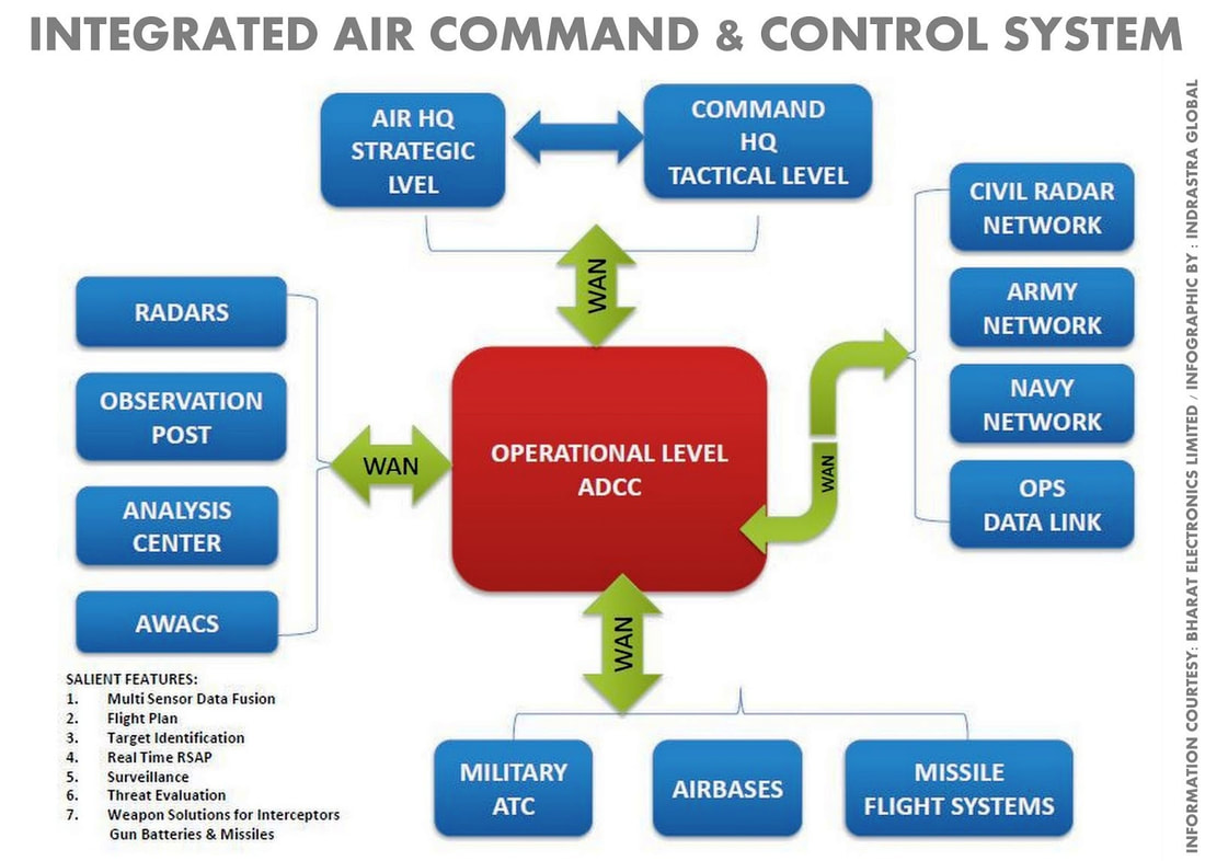 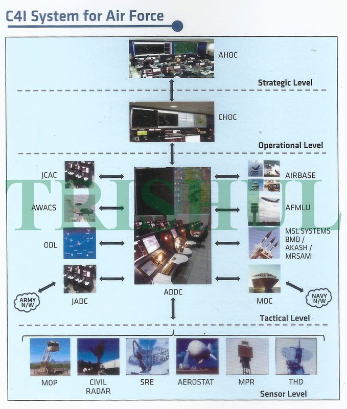 IACCCS Network Diagram Network For Spectrum Network For Spectrum (NFS) has been planned as an Exclusive Optical Fibre based ‘Nationwide Communication Network’ for Defence Services. This will be a Countrywide Secure, Multi service and Multi protocol Converged Next Generation Network based on Exclusive and Dedicated Tri-services Optical Transport Backbone. NFS will be a “Next Generation Network” based on Highly Resilient and Virtualized IP/ MPLS backbone and Gigabit Optical Access Networks based on Fault Tolerant Carrier Ethernet transport technologies. The complete network will be controlled from Geo Redundant Central and Regional Network Operating Centres. The Department of Telecom laid 57,515 kilometers of optical fibre cable connecting 219 Army stations, 33 Navy stations and 162 points for the Air Force. It set up an exclusive defence band and Defence Interest Zone along 100 km of the international border, where spectrum will be reserved only for use by the Armed Forces. AFNet is Indian Air Force component of Digital Information Grid under "Network for Spectrum" project and the AFNet is likely to be extended and connected to the Digital Information Grid Project under implementation for the Indian Navy and the Indian Army. The country is divided into seven regions to carry out the network for spectrum project. In May 2018 the Cabinet Committee on Economic Affairs (CCEA), chaired by the Prime Minister Narendra Modi has given its approval for enhancement of budget by Rs 11,330 crore for NFS project. Air Force Network Air Force Network (AFNet) is an Indian Air Force (IAF) owned, operated and managed digital information grid. The fibre-optic network-based AFNet, replaced the IAF’s troposcatter-based communications network. Developed at a cost of Rs10.77 billion in collaboration with US-based Cisco Systems Inc, HCL Infosystems Ltd and Bharat Sanchar Nigam Ltd (BSNL), the AFNet incorporates the latest traffic transportation technology in form of internet protocol (IP) packets over the network using multi-protocol label switching (MPLS). A large voice-over-internet-protocol (VoIP) layer with stringent quality of service enforcement will facilitate robust, high quality voice, video and conferencing solutions. With these two critical elements IACCCS can plug in large number of new-generation ground-based radars , be it for airspace surveillance in search of airborne targets (like manned aircraft, ballistic and cruise missiles, attack helicopters and unmanned aerial vehicles), or coastal surveillance or ground surveillance. Integrated Air Command and Control System (IACCS), an automated command and control system for Air Defence (AD) operations will ride the AFNet . AFNet prove to be an effective force multiplier for intelligence analysis, mission planning and control, post-mission feedback and related activities like maintenance, logistics and administration. A comprehensive design with multi-layer security precautions for “Defence in Depth” have been planned by incorporating encryption technologies, Intrusion Prevention Systems to ensure the resistance of the IT system against information manipulation and eavesdropping. The network is secured with a host of advanced state-of-the-art encryption technologies. It is designed for high reliability with redundancy built into the network design itself. The AFNet is also expected to facilitate accelerated economic growth by providing radio frequency spectrum for telecommunication purposes. AFNET will be the largest Multi-protocol Label Switching (MPLS) network in the defence segment. At the AFNet launch, the IAF showcased a practice interception of simulated enemy targets by a pair of Mig-29 fighter aircraft airborne from an advanced airbase in the Punjab sector using the gigabyte digital information grid. During the AFNet-assisted operations, the Indian fighter jets neutralised intruding targets in the western sector, which was played out live on the giant screens at the Air Force auditorium offering a glimpse of the harnessed potential of the system. Various other functionalities contributing towards Network Centric Warfare were also showcased. These consisted of facilitating video from Unmanned Aerial Vehicle (UAV), pictures from an AWACS aircraft to the decision-makers on ground sitting hundreds of kilometres away, providing intelligence inputs from far-flung areas at central locations seamlessly. This was possible mainly with the robust networking platform provided by AFNet AFNET 1.0: AFNET 1.0 forms the backbone for the overall ICT infrastructure of the IAF. The Indian Air Force (IAF) developed the AFNET 1.0 in 2010. AFNET 1.0 project lifecycle got completed in 2017, but the IAF opted for subsequent extension of support upto 2020. AFNET 2.0: Owing to its future-ready architecture and high level of automation, AFNET 2.0 can be a game-changer. AFNET 2.0 will bolster the strength of the IAF on the following accounts:
Air Defence Command India’s first Air Defence Command will be operational by 2021 August 15. The Air Defence Command will be based out of Allahabad and will control air assets of the Indian Air Force (IAF), Army and Navy. It will be responsible for protecting military assets from airborne enemies and will be commanded by a three-star officer of the IAF. Apart from theatre commands, India will get three or four integrated commands to secure the Pakistan and China fronts. Sources said there could be two theatre commands on the China front which in turn will report to a higher command. On the Pakistan front, there will be one theatre command for Jammu and Kashmir which will include the Line of Control and the International Border. Theatre Commands are a long delayed step in reorganising India’s military and bringing jointness in the three services to increase efficiency. Essentially it is a compact unit that will control all military assets in a theatre of war and report to a single commander. General Bipin Rawat, India’s first Chief of Defence Staff, is mandated with wrapping up the project by the end of 2022. Conclusion Both India and china have long range radars, advanced SAM systems and Integrated Air Defense System. India currently lacks long range SAM Systems, which is certainly a weak point in Indian air defense capability. Induction of S-400 and XR-SAM will make up for this weak link. China already inducted S-400 and indigenous HQ-9 and its variants. Even though that’s the case the effectiveness of long-range SAMs depends on the country where they are deployed and how that country uses them. Their ranges allow them to target key enemy assets, such as aerial refueling tankers and airborne early warning and control aircraft. 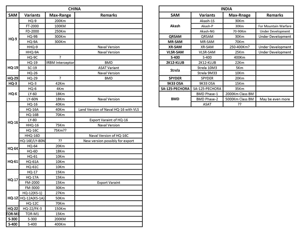 Indian & Chinese SAMs 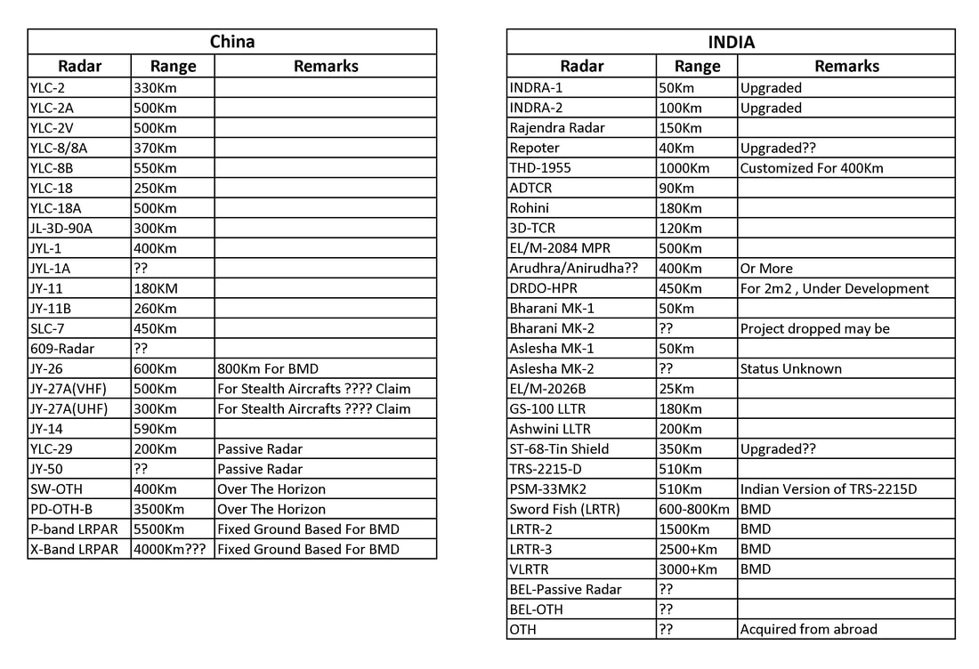 Indian & Chinese Radars Modern long-range SAMs such as the S-400 are only as good as the context. A standalone SAM System can’t do much to counter a formidable enemy such as Chinese PLAAF & Rocket force. A full S-400 battalion only has around eight missile launchers, typically with four missiles each. 32 missiles are certainly enough to cause serious harm to a limited attack but if an S-400 battalion is acting in isolation or is not backed up by other modern air defenses, it likely doesn't have enough missiles to withstand a determined onslaught. SAM systems are most effective as part of an integrated air defense system (IADS). Geographical factors affects heavily on a system's usefulness. Himalayan mountain region is one of the most unforgiving terrains on the planet. Mountainous features able to block the systems' sensors. A low-flying target can take advantage of geographical features and the curvature of the earth to avoid an interception. China deployed a variety of Radars and SAM systems across Indian borders but the effectiveness of these systems are highly doubtful. Most of the Chinese radar in Indian border is fixed ground based radars which are vulnerable to Indian attack. On the other hand India developed a variety of radars exclusively for mountain regions which can transport by road, rail, air and even by men. These radars can easily deploy any mountain top within few hours. At the same time Chinese long range radars are almost sitting ducks in the mountainous regions which will face serious limitations in its capabilities, most of these radars are operating in Tibetan plateau. (We will upload a separate article on this). China also deployed surface-to-air missiles, including the HQ- 9 and HQ-22, close to the Indian border during the on-going skirmish and is still deployed there. HQ-22 is one of the most capable China's air defense missile systems. HQ-22 has a range of up to 170 km and can reach targets at an altitude of up to 27 km. The effectiveness of these SAM systems is also doubtful mainly because of the terrain. China may be using these SAMs to protect their bases from Indian Air force attack. But with the terrain hugging capability India can give surprises to HQ-22 & HQ-9. One thing to note that is Indian SAM Systems such as MR-SAM is more capable than Chinese SAM Systems. Most of the Indian systems are tested and tested and proved in these mountain regions. This will certainly give India an edge over Chinese. Another problem with the Chinese systems is its reliability. Even though these systems look formidable in paper but not that much capable in the battle field. As an example, according to some reports Pakistan who bought LY-80(HQ-16) air defense systems from china are not much happy with the performance of the system. It is facing issues with the maintenance and more importantly with the rough terrain of Kashmir. Another example is the destruction of Chinese-made JY-27 radar of the Syrian Air Defense at Damascus airport. Which china claims to have stealth aircraft detecting capabilities up to 500 Km. We are not saying that Chinese systems are not capable but in the mountainous Himalayan region the Chinese systems may fail, while the Indian systems are testing in those mountain areas rigorously and making it perfect gives India an edge in air defense. |
AuthorPalash Choudhari Archives
June 2021
Categories
All
|
 RSS Feed
