|
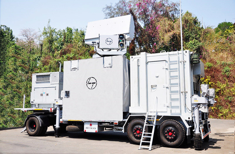
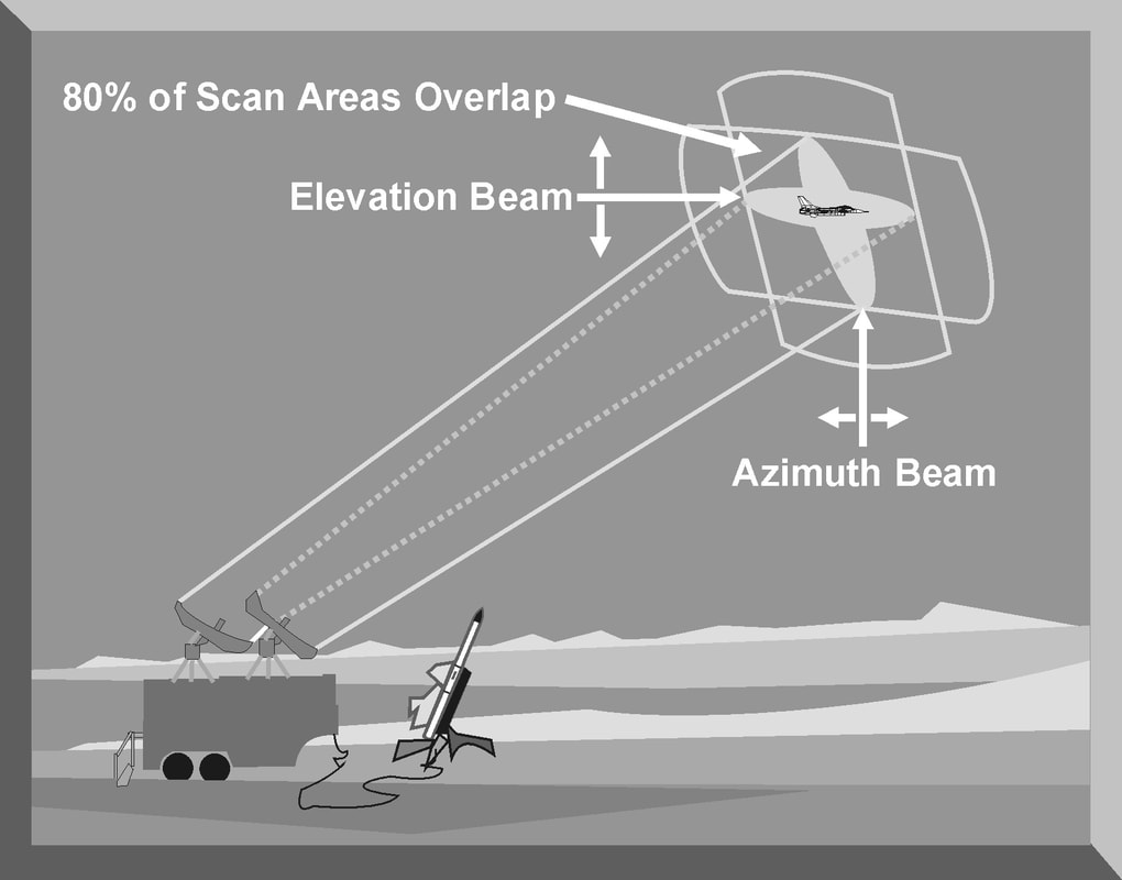
A target tracking radar (TTR) or Fire-control radar is designed to provide all the necessary information to guide a missile or aim a gun to destroy an aircraft. Once a target has been detected, either by dedicated search radar or by using an acquisition mode, the TTR is designed to provide accurate target range, azimuth, elevation, or velocity information to a fire control computer. A typical TTR has individual tracking loops to track a target in range, azimuth, elevation, or velocity. The antenna of the TTR is pointed at a single target, and the radar initiates acquisition and target track. TTRs normally employ automatic trackers to continuously measure target data. The range tracking loop employs an early gate/late gate range tracker to maintain automatic range tracking. The azimuth and elevation tracking loops generate error signals to position the antenna and maintain constant target illumination. The velocity tracking loop found on pulse Doppler and CW radars is used to reject clutter and generate accurate target radial velocity information. All this critical information is passed to a fire control computer for weapons employment. The fire control computer is programmed with critical information on the capability of the weapon to be employed. For a missile, the fire control computer is programmed with the aerodynamic and range capabilities of the missile. For antiaircraft artillery (AAA), the fire control computer is programmed with the ballistics for the gun, rate of fire, and tracking rate. The fire control computer uses the precise target information from the TTR and the programmed weapon's parameters to compute a firing solution. Once a firing solution has been computed, the fire control computer either fires the weapon automatically or alerts the operator, who fires the weapon. For missile employment, the fire control computer may continue to provide missile guidance and fusing commands until missile impact or initiation of an active missile guidance mode. For AAA engagement, the fire control computer computes the required lead angle, aims the guns, and initiates firing. To provide the required azimuth and elevation resolution, most TTRs use a high frequency to provide narrow antenna beamwidths for accurate target tracking. High frequency operation also allows the radar to transmit wide bandwidths. To provide the required range resolution, most TTRs employ narrow pulse widths and high pulse repetition frequencies (PRFs) to rapidly update target information. RANGE TRACKING In most TTR applications, the target is continuously tracked in range, azimuth, and elevation. Range tracking can be accomplished by an operator who watches an “A” scope presentation and manually positions a hand wheel to maintain a marker over the desired target return. The setting of the hand wheel is a measure of target range and is converted to a voltage used by the fire control computer. As target speeds and maneuvers increase, the operator may have extreme difficulty maintaining manual target range tracking. To avoid this situation, most TTRs employ an automatic range tracking loop. All pulse TTRs, which includes conical scan, track-while-scan, monopulse, and pulse Doppler radars, employ either a split gate or leading-edge automatic range tracking system. In a TTR, automatic range tracking serves two essential functions: (1) it provides the critical value of target range, and (2) it provides a target acceptance range gate that excludes clutter and interference from other returns. Since radar range is normally the first target discriminator used to initiate automatic target tracking, the second function is essential to the proper operation of the other tracking loops. A range gate circuit is simply an electronic switch that is turned on for a period of time after a pulse has been transmitted. The time delay for switch activation corresponds to a specific range. Any target return that appears inside this range gate is automatically tracked. The most common type of automatic range tracking is accomplished by a split-gate tracker. The automatic range tracking loop attempts to keep the amount of energy from the target return in the early gate and late gate equal. The range tracking error is computed by subtracting the output of the late gate from the output of the early gate. The amount of the range tracking error signal is the difference between the center of the pulse and the center of the range gate. The sign of the error signal determines the direction in which the gates must be repositioned to continue to track the target. Leading-edge range tracking is an electronic protection (EP) technique used to defeat range-gate-pull-off (RGPO) jamming. The leading-edge tracker obtains all range data from the leading edge of the target return. All RGPO cover pulse jamming tends to lag the target return by some increment of time. By differentiating the entire return with respect to time, the target return can be separated from the jamming pulse. Employing a split-gate tracker electronically positioned at the initial pan, or leading edge, of the returning pulse, the range tracking loop can track the target return and ignore any jamming signals. The range tracking loop then uses split-gate tracking logic to determine the magnitude and direction of range tracking errors and reposition the range gate. The width of the tracking gate is an important radar design consideration. The range gate should be sufficiently narrow to effectively isolate the target from other returns at different ranges. It should be wide enough to allow sufficient energy from the target echo to be displayed. The width of the range tracking gate is normally equal to the pulse width of the radar. Nearly all range tracking gates employ some form of automatic gain control (AGC). AGC is designed to limit target clutter and glint. It is also designed to avoid excessive false alarms. TRACK-WHILE-SCAN (TWS) TWS is a combined search and tracking mode that sacrifices the continuous target observation capability of the dedicated tracker in return for the ability to monitor a finite sector of airspace. This is accomplished while maintaining tracks on multiple targets moving through the covered airspace. There are two types of radar systems capable of TWS operation: conventional and phased array. Conventional track-while-scan threat radars use two separate antennas to generate two separate beams. These beams operate at two different frequencies and are sectored so they overlap the same region of space. This overlap area provides a tracking area for a single target. One beam is sectored in the vertical plane to give range and elevation. The other beam is sectored in the horizontal plane to provide range and azimuth. Each beam scans its sector at a rate of 5 to 50 times per second. This provides a rapid update on target range, azimuth, and elevation. TRACK-WHILE-SCAN (TWS) TWS is a combined search and tracking mode that sacrifices the continuous target observation capability of the dedicated tracker in return for the ability to monitor a finite sector of airspace. This is accomplished while maintaining tracks on multiple targets moving through the covered airspace. There are two types of radar systems capable of TWS operation: conventional and phased array. Conventional track-while-scan threat radars use two separate antennas to generate two separate beams. These beams operate at two different frequencies and are sectored so they overlap the same region of space. This overlap area provides a tracking area for a single target. One beam is sectored in the vertical plane to give range and elevation. The other beam is sectored in the horizontal plane to provide range and azimuth. Each beam scans its sector at a rate of 5 to 50 times per second. This provides a rapid update on target range, azimuth, and elevation. The two TWS antennas generate their beams using an electromechanical principle. Each antenna provides inputs to its own display and provides angle and range information for all targets in the coverage of the radar. The display from the elevation beam is calibrated in range and elevation, while the display from the azimuth beam is calibrated in azimuth and range. Operators position a cursor over the returns on these displays using range as the primary parameter. Once a target has been designated for engagement, the radar automatically attempts to keep the tracking axis of the radar beams centered on the target. Once the target is designated by the operator, the range gate is enabled and tracks the target using a split-gate tracker. The azimuth and elevation tracking loops receive information only from targets inside the range gate. As the beams scan across the target, a burst of pulse returns is received that have an amplitude envelope corresponding to the beam pattern. The azimuth tracker is typically a split-gate tracker, identical in concept to a split-gate range tracker. However, range delay time is replaced by azimuth scan time. The azimuth tracker uses a left gate and right gate. Each gate integrates its share of the target return to generate a voltage/time value. When the azimuth gate is centered on the target, the areas are equal and the error signal (right gate minus left gate) is zero. The azimuth tracking loop sends signals to the antenna servos to keep the target centered in the scan area. Elevation tracking is accomplished in the same manner by using an up gate and a down gate. The elevation tracking loop also sends signals to the antenna servos to keep the target centered in the scan area. Once the target is designated and the radar is automatically keeping the radar return centered in the tracking area, target range, azimuth, and elevation information is sent to a fire control computer. The radar continues to provide information on other targets in the scan area. The fire control computer indicates the firing solution has been achieved for the designated target, and a missile is launched. The radar tracks the target and the missile and provides in-flight corrections to the missile right up to the moment of missile impact. These corrections are based on both target and missile azimuth, range, and elevation information. Information is passed to the missile from a dedicated antenna on the radar to special antennas on the missile. Commands from the radar to the missile are called uplink guidance commands. Information from the missile back to the radar and fire control computer is called downlink information. The advantages of a conventional TWS radar include the following:
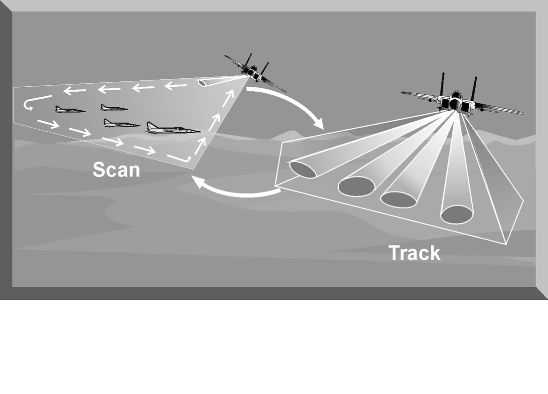
The primary disadvantages of a conventional TWS radar include: (1) A large resolution cell due to the wide azimuth and elevation beams, and (2) Vulnerability to modulation jamming based on the scan rate of the independent beams. Many modern radars employing a planar or phased array antenna system have a TWS mode. The radar does not really track and scan simultaneously, but rapidly switches between search and track The most common air-to-air radar system uses a planar array antenna. In the scan mode, the radar antenna generates a pencil beam and uses a raster scan to detect targets in the search area. Targets detected are presented to the pilot on the aircraft's radar display. In the track mode, the antenna generates multiple beams to illuminate individual targets. The radar typically uses monopulse or pulse Doppler techniques to update target range, azimuth, elevation or velocity.The radar initiates a track file on each detected target that contains all current data on the target and an estimate of future target position. As the radar switches between track and scan modes, target parameters are updated in the tracking loop. The new target information is compared to the predicted information in the measurement data processing cell. If the two sets of data agree within certain limits, target position and information are updated. This process is called gating. If the updated target information does not correspond to the predicted values, the information is sent to the correlation processor. The correlation processor attempts to resolve the conflict based on further refinement of target data. If the correlation processor cannot assign the target parameters to an existing track file, a new track file is generated and displayed. The obvious advantage of a planar/phased array TWS radar is that it can search a large volume of airspace while tracking individual targets. The number of targets that can be tracked is limited by the number of beams the radar can generate. Planar/phased array radars have increased peak and average power when compared to pulse radar systems. Since the radar beam of a planar/phased array radar is electronically controlled and can rapidly change beams and scans, it is resistant to many jamming techniques. The primary disadvantages of a planar/phased array TWS radar include its complexity, cost, and reliance on computer processing. LOBE-ON-RECEIVE-ONLY (LORO)
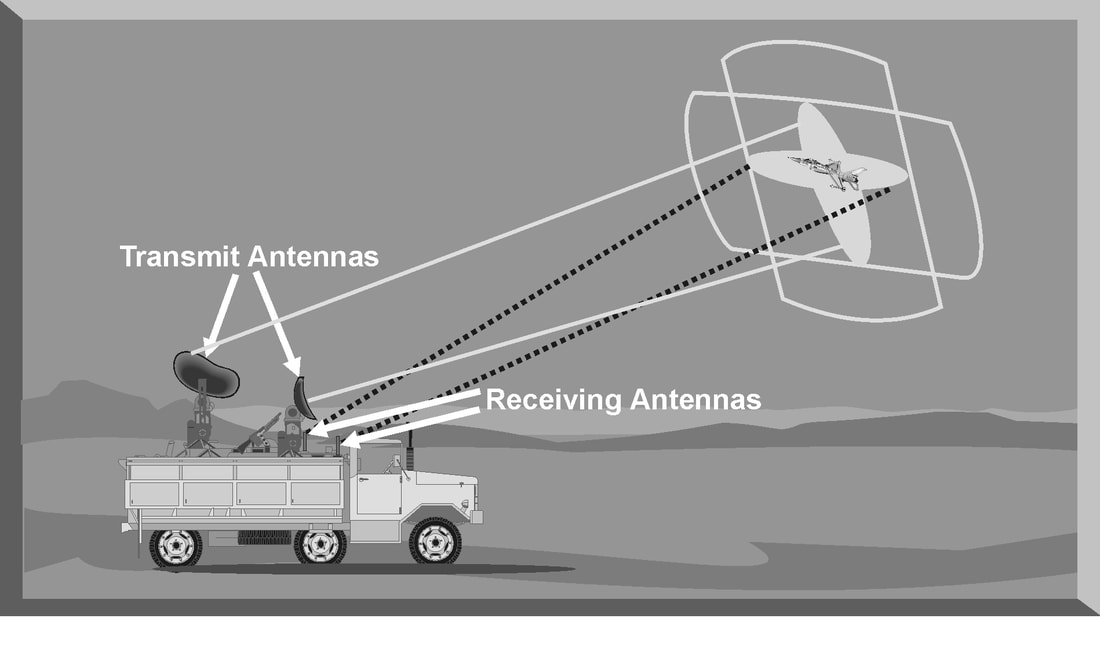
LORO is a mode of radar operation developed as an EP feature for a track-while scan radar. LORO can be employed by any radar that has the capability to passively track a target. In a LORO mode, the radar transmits a continuous signal from a set of illuminating antennas. This continuous signal hits the target, and the return echo is received by a different set of receive antennas . The receive antennas are passive and generate azimuth and elevation tracking signals by electronically scanning the reflected signal. The tracking signals are sent to the antenna servos to keep the illuminating antennas pointed at the target and centered in the receive antenna tracking area. The range tracking circuit uses the time delay between the transmission and reception of the illuminating antenna signals. A split-gate tracker is used to provide range tracking. The illuminating antennas used in the LORO mode have very narrow beam widths and transmit at a high power level. This reduces the effectiveness of noise jamming techniques against a radar employing a LORO mode. In addition, the continuous signal from the illuminating antennas negate the effectiveness of most angle deception jamming techniques designed to defeat TWS radars. These specialized jamming techniques exploit the scan rate of TWS antennas. In the LORO mode, the illuminating antennas do not have a scan rate. The limited effectiveness of both noise and deception jamming techniques is the major advantage of the LORO mode. The LORO mode also provides a track-on-jam (TOJ) capability to exploit noise jamming techniques. In a TOJ mode, the receive antennas passively track any detected noise jamming signals. The radar assumes that the most intense jamming signal is the target. The receive antennas process the strongest jamming signal as if it were a target echo from the transmit antenna signal. The receive antennas generate azimuth and elevation tracking signals to keep the jamming signal centered in the tracking area. The TOJ mode does not provide target range. |
AuthorPalash Choudhari Archives
June 2021
Categories
All
|


 RSS Feed
