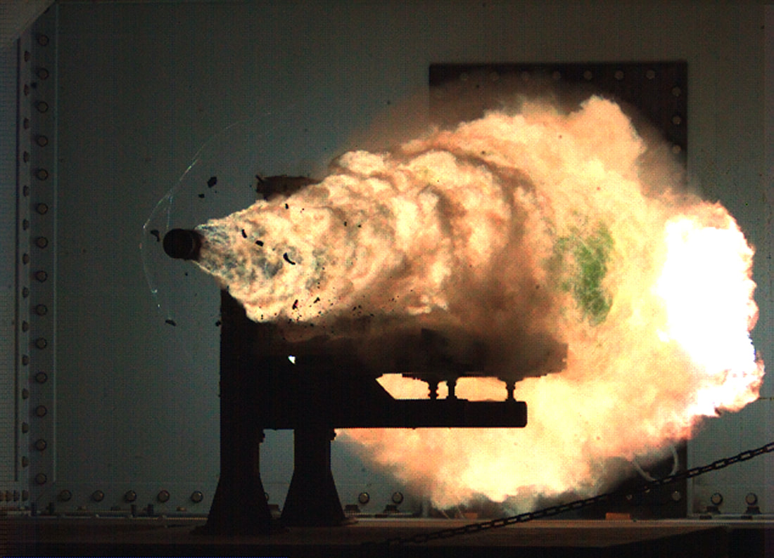
 A railgun is a device that uses electromagnetic force to launch high velocity projectiles, by means of a sliding armature that is accelerated along a pair of conductive rails. US is the only country which developed a working rail-gun. Countries like India, China and Russia are researching to develop their own rail-guns. Below you can read a research paper published on Defense Science Journal in 1994. Even though it was an old article the basics are pretty much same. ABSTRACT A rail gun using electromagnetic propulsion was developed to launch hypervelocity projectiles. A 240 kJ, low inductance capacitor bank operating at 5 k V powered the rail gun. Launchers and projectiles were designed and developed for this purpose. The currents producing the launch forces are of the order of hundreds of kA. Even very low impedances for the current through the rail gun circuit are substantial sources of energy losses. A simulation code was developed to optimize the performance of the rail gun. Control and instrumentation facilities were set up along with a computer-based data acquisition system for measurement and analysis. The capacity to launch projectiles of 3-3.5 g weight to a velocity of more than 2.00 km/s was demonstrated. INTRODUCTION A facility was devel6ped to launch hypervelocity projectiles using electromagnetic energy. The projectiles were launched using a railgui1. The rail gun consists of two parallel rails and a conducting metalic foil placed behind the insulating projectile. When a high current flows through the rails, the foil explodes and forms a plasma armature. The force acting on the armature is given by Force at time t = 0.50 * Inductance per unit length of launcher * (current through the launcher at time t) 2 The rail gun currents are in the region of Hundreds of kA. This Lorentz force accelerates the projectile 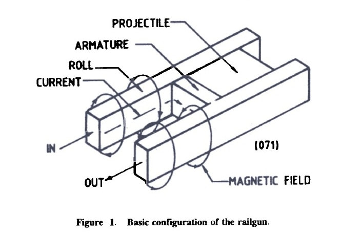 POWER SUPPLY An electromagnetic propulsion system requires a storage device with an energy density comparable to that of chemical explosives. The most expensive and technologically difficult part of the system is the high-energy electric source. The power sources considered for electromagnetic propulsion are well researched Capacitor Bank and Charging Unit The capacitor bank was used as a power source owing to its availability and lower cost despite its lower energy density. A low-inductance, 240 kJ capacitor bank was set up to provide the basic power to the railgun. A high-voltage charging unit was used to charge the capacitor bank. 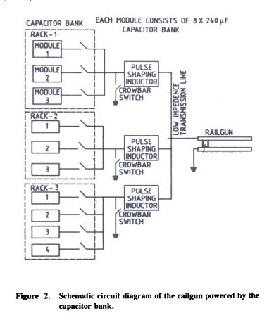 High Current Switches The capacitor energy is switched into the railgun by high-power ignitrons. When the peak current is reached, additional high-power ignitrons are used to crowbar the capacitors out of the circuit to obtain a dc pulse. This minimises the stress on the capacitors, the launcher and the projectile. Transmission Lines Low-inductance transmission lines were made using sandwiched conducting plates to maximize the energy transfer to the load. The transmission lines are subjected to repulsive forces owing to the passage of current through them. These, forces were 'estimated to provide proper bolting and bracing to avoid deformation of the transmission lines. LAUNCHER AND PROJECTILE Launchers and projectiles are subjected to high plasma pressures. High magnetic fields and high temperatures. In the present railgun set-up, the plasma pressures generated varied between 100 and 150 MPa. Launcher A simple, single pulse driven rail gun launcher was developed with a minimum of metal components in proximity to the bore to maximize the inductance of the launcher and to improve the launch efficiency. The launcher has a 12 mm square bore cross-section. The launcher was fabricated with lengths ranging from 1 to 2 m. The following launcher designs were used for the firings:
The launchers with the last two design modifications proved more reliable and durable than the launchers based on the first design. Thermal energy transfer from the rails leads to ablation and the melting of the bore materials. Such ablation degrades the performance of the railgun by adding parasitic mass to the plasma. The bore materials should have a high melting point and superior erosion and ablation resistance. High rail conductivity necessitated the use of copper rails. Polycarbonate and fiberglass were most suitable as bore materials. Loose bore to projectile tolerances or variation in bore dimensions can result in plasma leakage. Most of the launchers showed marked deterioration after a few shots. The deterioration could be attributed to changes in the bore dimensions due to the rail insulator ablation. Substantial deposits of carbon were observed inside the bore of the gun and needed cleaning. Projectile The projectiles are made of Perspex or polycarbonate cubes of 12 mm length. Perspex projectiles tended to shatter. Polycarbonate projectiles survived the high plasma pressures. The plasma and the solid armature were both used for carrying the high currents. Most firings were carried out using plasma armature. A plasma armature is formed when Al/Cu foil melts/explodes on the passage of high currents. The foil vaporizes by joule heating to produce plasma to drive the armature. A neoprene obturator was placed at the rear of the projectile to seal the bore against plasma leakage around the projectile. As a deviation, a solid metallic projectile acting as an armature was also used to carry the current. 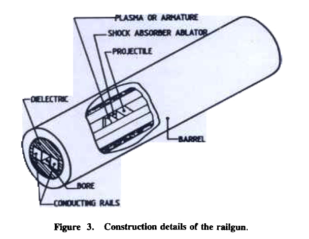 DATA ACQUISITION AND SIMULATION Data Acquisition A computer-based data acquisition system was set up to monitor important parameters that affect the performance of the railgun. Current transformers and Rogowski coils were used to measure the rail currents in the range6 of 100 to 500 kA. Magnetic probes were used to get the position-time profile of the projectile inside the bore of the gun and railgun current distribution. These probes help detect plasma leakage and formation of secondary arc. The velocity outside the bore of the gun was measured using shorting screens. A high-speed camera was set up to measure the velocity of the projectile and establish the integrity of the projectile at the muzzle end. This is a non-contact method and is free from electromagnetic pickups. Simulation A simulation code was developed to predict the performance of the railgun. The performance of the model was evaluated by monitoring different parameters ANALYSIS All measurements were supported by appropriate software developed to analyse the entire performance of the railgun. The current-time data are used to predict the displacement, velocity and acceleration of the projectile and the plasma pressure. RESULTS Some typical railgun trial results are given in Table. Projectile velocities greater than 2000 m/s were obtained for trial no’s 1 to 3. The efficiency varied between 4 to 5 per cent with railgun current in excess of 260 kA. Plasma leakage and formation of secondary arcs were responsible for the lower projectile velocities than expected from the computer model for trial no’s 5 to 7. Trial no.7 was done using a solid conducting projectile made of aluminium. An armature was kept behind the projectile with no ablator. The armature vaporized and the plasma escaped ahead of the projectile. This led to a lower system efficiency and projectile velocity. A solid projectile made of Perspex and armatures made of several copper foils were used in trial no.4. The mass of each foil was kept around 100 mg to avoid the melting of the armature owing to the high railgun current. 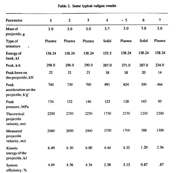 CONCLUSION Our study has shown that projectiles attain hypervelocity’s by using a single small square bore railgun. In the existing railgun facility the efficiency varied between 4 to 5 per cent. Significant improvement in the efficiency of the railgun set-up is one of the key issues that will determine the use of railguns for various weapon applications. Hence we carried out detailed modelling and simulation of the entire railgun system. The results from the simulation were validated with the measurements. Measurements made at high common mode voltages of around 1000s of volts and high electromagnetic noise were exceptionally good, providing reliable and repeatable records. Intact projectile launch and 2-3 m of free flight projectile were studied using high-speed photography when punctures in the shorting screens were observed. Using a high-speed camera the integrity of the projectile was established beyond doubt. A 12 mm cubical polycarbonate projectile weighing about 3 g could defeat a 6 mm aluminium sheet at 2 m from the muzzle end of the gun). The complete railgun system was also placed in a 5 m long vacuum chamber to study the railgun performance. Our studies are as yet inconclusive. Owing to the failure of some odd capacitors in the capacitor bank, repetitive trials could not be carried using the full energy of the bank. The energy extracted from the capacitor bank varied between 120 and 160 kJ. The kinetic energy of the projectiles can be increased substantially by using a higher-energy capacitor bank as a power source 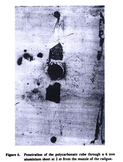
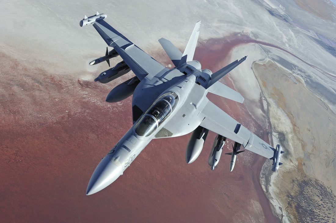
Due to unknown reasons Rail-gun development was not completed at that time. But from this press release of Ministry of Defense, it is clear that DRDO restarted their work in the field of Electromagnetic rail gun along with other futuristic technologies like Supersonic Missile Assisted Release of Torpedo, Stealth Wing Flying Test bed, AESA Based Integrated Sensor Suite, Multi-Agent Robotics System etc http://pib.nic.in/newsite/mbErel.aspx?relid=158187 Info Source Defense Science Journal, Val 44, No 3, July 1994, pp 257-262 S.G. Tatake, K.J. Daniel, K.R. Rao, A.A. Ghosh, and I.I. Khan Armament research & Development Establishment Pune-410121 There are five main things a pilot must remain aware of when contemplating aerial engagement, of which, getting sight of your opponent and keeping sight of them are the most important. Other major factors influence a dog fights are, thrust-to-weight ratio, wing loading, and the "corner speed" (the maximum/minimum speed at which the aircraft can attain the best turning performance). Apart from this, variable limitations must also be considered, such as turn radius, turn rate, and the specific energy of the aircraft. The concept of energy awareness during air combat is not new. Wise use and conservation of energy during combat will increase your chances of victory.  FABRICATION MATERIALS Missiles are generally made from aluminium and its alloys, steel, magnesium and titanium. The major concern is the strength-to-weight ratio of the material. Higher this ratio the better. On account of the high temperatures encountered by missiles flying at supersonic speeds and needs for lighter materials, newer materials are coming into usage. Fibre-reinforced plastics (FRP) like the carbon-carbon variety, graphite compounds, molybdenum, beryllium, etc. Some of the important factors calling for adequate caution during material selection are as follows:
  The individual components of a radar determine the capabilities and limitations of a particular radar system. The characteristics of these components also determine the countermeasures that will be effective against a specific radar system. Here we will discuss the components of basic pulse radar, continuous wave (CW) radar, a pulse Doppler radar, and monopulse radar. PULSE RADAR SYSTEM The most common type of radar design is the pulse radar system. The name describes a process of transmitting discrete bursts of RF energy at the frequency of the radar system. The time that pulses are transmitted determines the pulse repetition frequency (PRF) of the radar system. A pulse radar system can figure out range and azimuth. Range is determined by the time that it takes a pulse to go to a target and return. Target azimuth is determined by the relative position, or antenna orientation, when the pulse strikes the target. 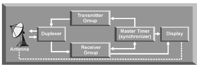 A major important item in the aerodynamic missile configuration is the wing or the main lifting surface. A great variety of wing planforms or configurations are used. Without going into the detailed analyses for optimisation of the configuration, only the names of a few well-known theories are stated here. The linearised theory is used in supersoninc flow over wings. This theory is derived from the exact differential equation of steady compressible flow. There are also a few equations of first order and linear equations called 'Ackeret Theory'. The basic assumptions made are: (a) the airfoil is thin, and (b) the flow is two dimensional, to mention a few typical ideal assumptions which one comes across many a time. A few higher order terms have been derived making use of constants called the 'Busemann constants' owing their name to the man who derived them. This derivation makes use of expansion series which are mainly mathematical. A straight wing planform is the one which is often used. Two other basic wing planforms used are delta and swept back wings. There are many variations of these basic planforms. Due to the advantages and disadvantages associated with each of the basic planforms used, a thorough study involving their aerodynamic efficiency, structrual weight and cost of manufacturing is often called for. In the analysis of wings of arbitrary planform it is important to know whether the leading (and trailing) edge is subsonic or supersonic since the pressure distribution is markedly different for each condition. Extensive experimental investigations have been conducted to determine and compare the aerodynamic characteristics (commonly called as chics') of the basic planforms for practical applications. The factors taken into account are Reynold's number, fluid viscosity and such other dimensional properties. Thus, airfoil is the cross section of a wing which gives a minimum drag and a maximum lift. The pressure over an airfoil is primarily a function of the angle between the free stream air direction and the surface. The airfoil shape or section for supersonic application is noticeably different from those sections used in the subsonic region. In general, sharp nosed symmetrical airfoil sections of the double wedge, modified double-wedge, or biconvex variety result in the most efficient aerodynamic design. 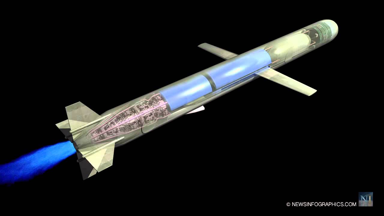 |
AuthorPalash Choudhari Archives
June 2021
Categories
All
|
 RSS Feed
