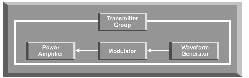
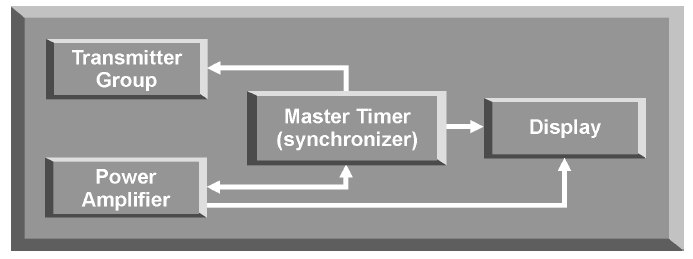
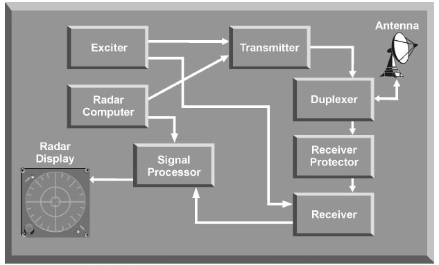
 The individual components of a radar determine the capabilities and limitations of a particular radar system. The characteristics of these components also determine the countermeasures that will be effective against a specific radar system. Here we will discuss the components of basic pulse radar, continuous wave (CW) radar, a pulse Doppler radar, and monopulse radar. PULSE RADAR SYSTEM The most common type of radar design is the pulse radar system. The name describes a process of transmitting discrete bursts of RF energy at the frequency of the radar system. The time that pulses are transmitted determines the pulse repetition frequency (PRF) of the radar system. A pulse radar system can figure out range and azimuth. Range is determined by the time that it takes a pulse to go to a target and return. Target azimuth is determined by the relative position, or antenna orientation, when the pulse strikes the target. 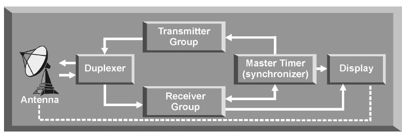 The purpose of the transmitter is to deliver a series of high-energy bursts of radio frequency (RF) energy to the antenna. The transmitter group of modern pulse radar normally consists of a pulse generator or waveform generator, a modulator, and some kind of power amplifier. Transmitter Components
 Duplexer A duplexer is required when both the transmitter and receiver use the same antenna. The duplexer acts as a rapid switch to protect the sensitive receiver from damage when the high-power transmitter is on. When the transmitter is off, the duplexer directs the weak target signals to the receiver. The duplexer's main purpose is to minimize power loss and maximize isolation. Power lost in the duplexer during transmission reduces the maximum detection range of the radar. Isolation refers to the amount of transmitter power that “bleeds through” the duplexer to the receiver during transmission. This “bleed through” must be extremely small to avoid receiver saturation or damage. Receiver The capabilities of the receiver group are critical to radar performance. The ability of the radar receiver to detect the presence of the target return and extract the required information is limited primarily by noise. Noise can enter the receiver through the antenna along with the target return. This type of noise is called external noise. Noise generated within the receiver is called thermal noise. Radar noise can never be completely eliminated. Minimizing noise is the most important consideration in the design of the sensitive receivers used with modern radars. In addition, relative immunity to noise makes a radar system more resistant to jamming. 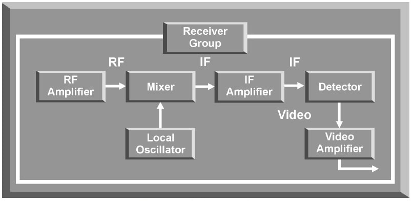
The A scope is used to display target range or velocity. Threat systems using A scope displays include air interceptors (Als) with range-only radar, surface-to-air missiles (SAMs), and radar-directed antiaircraft artillery (AAA) systems. SAM and AAA systems may use the A scope for range or velocity information, and other radar displays for azimuth and elevation data. The A scope displays range or velocity in relation to amplitude. The operator must distinguish the target return from other returns, including ground return and noise. The B scope is used to display target range and azimuth. Threat systems using B scope displays include Al and SAM systems. The position of the target return to the right or left of the centerline of the screen shows the azimuth of the target. The position of the target return in relation to the bottom of the display, or zero range, shows target range. The RHI scope is used to display range and elevation. The RHl scope is used with height finder radars, and a modified RHI scope is used for ground-controlled approach (GCA) radars. The sweep trace of the display produces a fan-shaped display with the vertex at the lower left of the scope. The antenna sweeps up and down and is synchronized with the display. The PPI display is probably the best known radar display. The display represents a map picture of the area scanned by the radar beam, usually 360 degrees. The PPI display is used by early warning, acquisition, ground-controlled intercept (GCI), and SAM radar systems. The target return's angular position shows target azimuth, while distance from the center of the display shows range. CONTINUOUS WAVE (CW) RADAR A continuous radar transmission from the antenna requires that classic CW radars have two antennas, one for transmission and one for reception. Since a continuous transmission results in a continuous echo signal, it is impossible to tell what part of the echo is associated with any particular part of the transmission. This makes conventional range determination (based on timing) impossible. However, the simple application of the Doppler principle provides a means for a CW radar to track a target. The Doppler principle deals with the fact that a radar return from a moving target will be shifted in frequency by an amount proportional to its radial velocity relative to the radar site. Using the difference in frequency from the transmitted signal to the received signal, a CW radar can separate the target return from clutter, based on a change in frequency. This type of radar is called CW Doppler radar. In simple CW Doppler radar, the transmitter transmits a continuous signal at the radar's operating frequency. This signal is reflected by a moving target and travels back to the receiving antenna. The frequency of the reflected signal (fd) is the frequency change due to the Doppler effect. This target frequency is passed to the detector. The transmitted frequency (fo) is also fed to the detector as a reference. The detector notes the difference between the transmitted and received frequencies and passes this frequency to the Doppler filters. The Doppler filters only allow Doppler frequencies within a certain range to pass through. A filter is required for each Doppler frequency. The number of Doppler filters determines the number of targets that the radar can resolve in velocity. The output of each Doppler filter is amplified and passed to its own display. The display is normally an A scope. 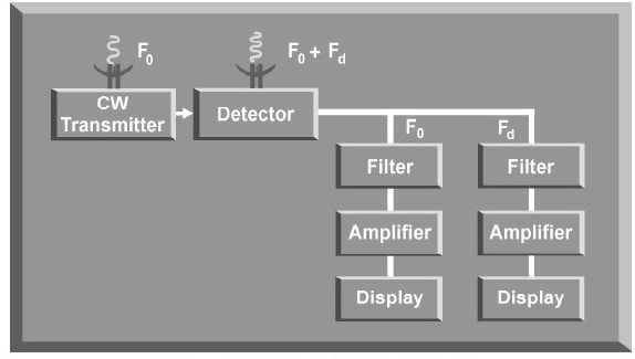 PULSE DOPPLER RADAR Pulse Doppler radars combine the advantages of both pulse and Doppler radar systems. Because the signal is pulsed, the radar can determine range, azimuth, and elevation, similar to conventional pulsed radar. A pulse Doppler radar can also compute overtake or rate of closure, relative to the radar system on a pulse-to-pulse basis. Pulse Doppler radars also use multiple PRFs to eliminate target eclipsing and for range determination in medium PRF. The beauty of a pulse Doppler radar is that it eliminates ground clutter and provides range, azimuth, and velocity resolution.
 |
AuthorPalash Choudhari Archives
June 2021
Categories
All
|
 RSS Feed
