|
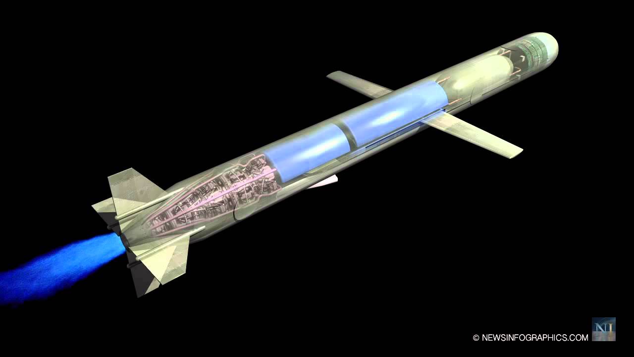
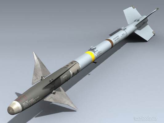
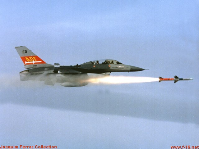
A major important item in the aerodynamic missile configuration is the wing or the main lifting surface. A great variety of wing planforms or configurations are used. Without going into the detailed analyses for optimisation of the configuration, only the names of a few well-known theories are stated here. The linearised theory is used in supersoninc flow over wings. This theory is derived from the exact differential equation of steady compressible flow. There are also a few equations of first order and linear equations called 'Ackeret Theory'. The basic assumptions made are: (a) the airfoil is thin, and (b) the flow is two dimensional, to mention a few typical ideal assumptions which one comes across many a time. A few higher order terms have been derived making use of constants called the 'Busemann constants' owing their name to the man who derived them. This derivation makes use of expansion series which are mainly mathematical. A straight wing planform is the one which is often used. Two other basic wing planforms used are delta and swept back wings. There are many variations of these basic planforms. Due to the advantages and disadvantages associated with each of the basic planforms used, a thorough study involving their aerodynamic efficiency, structrual weight and cost of manufacturing is often called for. In the analysis of wings of arbitrary planform it is important to know whether the leading (and trailing) edge is subsonic or supersonic since the pressure distribution is markedly different for each condition. Extensive experimental investigations have been conducted to determine and compare the aerodynamic characteristics (commonly called as chics') of the basic planforms for practical applications. The factors taken into account are Reynold's number, fluid viscosity and such other dimensional properties. Thus, airfoil is the cross section of a wing which gives a minimum drag and a maximum lift. The pressure over an airfoil is primarily a function of the angle between the free stream air direction and the surface. The airfoil shape or section for supersonic application is noticeably different from those sections used in the subsonic region. In general, sharp nosed symmetrical airfoil sections of the double wedge, modified double-wedge, or biconvex variety result in the most efficient aerodynamic design. In the final selection of airfoil shape, one must consider also the structural efficiency and manufacturing cost as well as its aerodynamic efficiency. From the latter standpoint the double wedge has the lowest drag for a given thickness ratio, whereas the biconvex section has the lowest drag per unit strength. From the manufacturing standpoint the modified double wedge is preferred, where solid sections are involved. The sharp leading and trailing edges may have to be rounded to provide local structural integrity as well as to minimize the aerodynamic heating effects. Generally speaking, the biconvex should be used on large wings which are not solid sections and modified double wedge should be used for smaller sized solid wings. Finally, the size and area of the wing of a missile may be dictated by considerations of range and maneuverability requirements, types of design and compatibility with subsystem operation. The performance chics of a missile are determined from the magnitude of the pertinent forces (i.e. thrust and drag weight). Drags occur in various forms as friction drag, pressure drag, induced drag and interference drag. Various theoretical methods of evaluation of drag characteristics are available and are used for their corresponding applications and the missile performance determination. Friction drag is mainly due to the skin friction of the missile and depends on the type of flow (i.e. laminar or turbulent). Pressure or form drag depends on the contour and the pressure distribution over it. The form drag is generally small in the subsonic flow and often neglected. However, in the transonic and supersonic region this constitutes for a good proportion of the total missile drag. This can be determined both by experimental test data and also by computing machines using highly mathematical relations one of which is called the 'transonic area rule'. Induced drag is the drag due to the normal force and is approximated mathematically. The drag of composite configurations (like say the body plus wing, etc.) constitute the interference drag and these are experimentally and also analystically (with some difficulty) are predicted for a general nature of the missile behavior and performance. The response characteristics of the complete guidance control and airframe tap determine the effectiveness of a guided missile weapon system, in terms of accuracy and kill probability. The aerodynamicist's or the configuration designer's task is to see that sufficient static and dynamic airframe stability and damping are provided in the air frame system. The two important design requirements are stability and maneuverability. Various mathematical graphical, iterative procedures .using manual computation or by using computers are available to analytically predict these two conflicting needs. These apply equally for forward or aft control. The momentum equations of motion are applied along the three axes and are used to study the dynamic stability. Air loads on the missile too are to be systematically analyzed. In addition, other loads during flight conditions are to be of interest for the determination of the type and capacity of' the servo system used for actuating the aerodynamic movable surfaces. Finally, thermal loading or aerodynamic heating must be estimated in order to determine the best available material and optimum construction for the airframe. Aerodynamic launching problems too surface frequently during firing of missiles. Design of missiles fired from ground launched (static or mobile), ship board or from a high-speed parent aircraft are some of the few challenging tasks. It is understood that beam-riding missiles have occasionally lost 'beam lock-on' during their boost or launching phase as the result of excessive flight path excursion, resulting in aborted flights. Detailed analyses of the sources and magnitudes of both internal and external forces acting on the missile during its launching phase are worked out lest these forces should cause undesirable launching dispersion. Also design modifications may be incorporated to assure a satisfactory launch. In the case of an air-launched missile, aircraft-missile compatibility must be realized. Safety of parent aircraft must be assured in addition to satisfying the requirement that the dispersion of the missile during launch must not exceed the limit dictated by guidance considerations. Retro-fitting the missile to the parent aircraft becomes a difficult problem when aircraft and missile designers are working separately as two distinct groups. At such a state of 'frozen' design, modifications cannot be easily made. From the considerations of safety criteria, the following should form a guide for both the missile and aircraft designers.
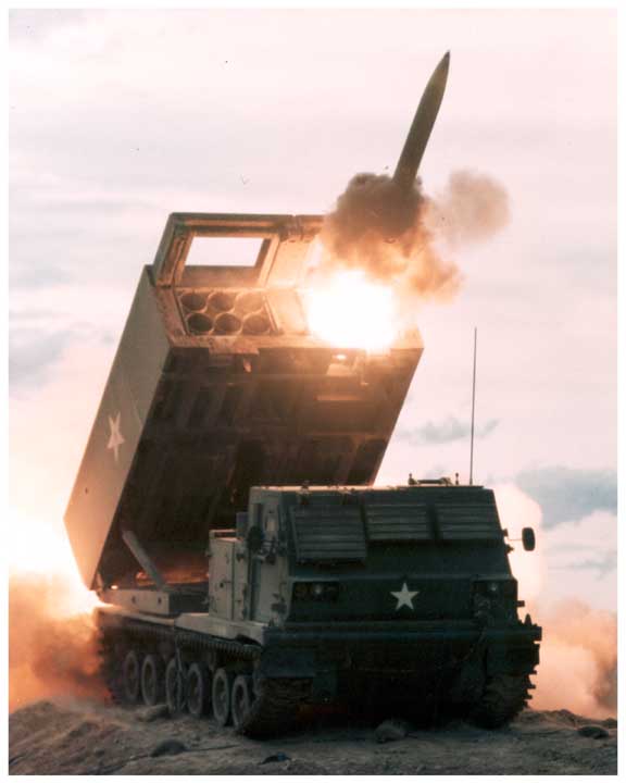
Ground launch problems are of particular interest. These may be categorized into
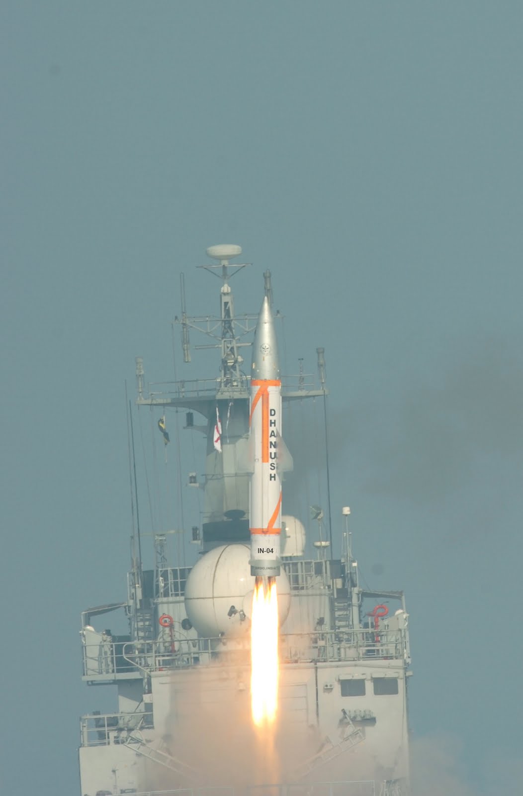
The former effects are studied from the standpoint of missile guidance and missile component operation, while the fatter effects are concerned primarily with the safety to the launching crew and surrounding areas. Excessive missile dispersion at launch should be avoided. These are mainly due to causes like launcher deflection, missile tip-off from the launcher, thrust and fin misalignments and atmospheric disturbances such as tail wind, crosswind and gusts. The advent of lethal weaponry using atomic and nuclear warhead carrying missiles apart from the explosive warheads poses an extremely serious problem of safety even to the friendly troops, cities and installations. Therefore, a pronounced emphasis on 'range safety' has become a grave but important necessity for clearance of any launch or firing. The flight path and resultant impact point can be extremely erratic if guidance and control system failures occur. Hence reliability of the components as well as a proper arming system are major requisites in any missile system. Ideally, it is impossible to achieve 100 per cent reliability for the overall missile performance. Therefore from a realistic standpoint, the problem of range safety is analyzed. Due to any reason, when the missile ‘misbehaves’ the destruct system is called for which retards the missile's forward movement and prevents any damage to the surrounding. The maximum area surrounding the launch site, within which the missile can impact due to malfunctioning, if any, is calculated to determine the various failure modes and their consequences. As a practical example, India's first indigenous surface-to-surface missile Prithvi had a destruct system to be employed in the event of any malfunction. The philosophy consisted of cutting the fuel and oxidizer tanks and allowing the two to mix in the air itself and burn. The explosive propellants would thus get hypergolically consumed (self burnt without the aid of any initiator or igniter), thereby preventing any ground and water pollution. Cutting open the tank was designed to be achieved by linear shaped charges which are thin rods/tubes filled with explosive material. This Command Destruct System (CDS) is proven for its reliability and safety. Now, a few words about shipboard and underwater launchers. Space limitation and motions of the ship during both check-out and launching are to be taken care of which launching such missiles in addition to protection to both the ship and personnel from rocket motor blast effects. Little information is available on test results on launching missiles from underwater. The state of the sea should also be looked into in determining the trajectory of the emerging missile. Rocket motor ignition for an underwater launched ballistic missile occurs when the missile has cleared from the surface of water to prevent any back pressure.
Structural design considerations go hand in hand with the finalization of aerodynamic configuration in the preliminary design. The primary function of the structural design engineer is manifold:
Adequate factors of safety are applied to the limit or actual flight ground handling loads to assure that all stresses are below the ultimate or yield strength of the material from which the missile structural components are fabricated. Typical values of factors of safety are 1.25, and 1.5 to 2 in some cases. On the whole, the structural design should be realistic and adequate to satisfy the overall mission requirements of the weapon system. The classical equation of bending of beams and related theories for various solid sections are applied during overall structural analysis. Finite element analysis is very widely used in analyzing shaped section, propellant tanks, cut outs, etc. on the structure. Leave a Reply. |
AuthorPalash Choudhari Archives
June 2021
Categories
All
|
 RSS Feed
