|
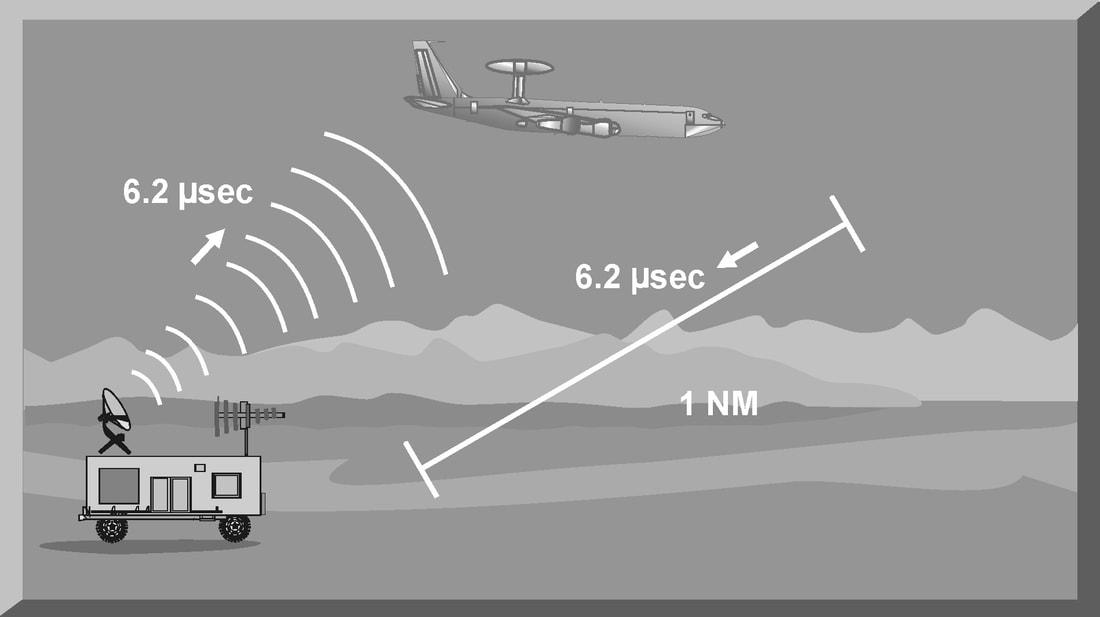
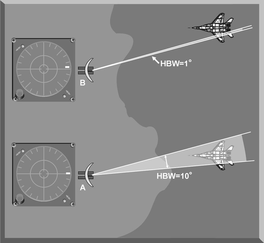
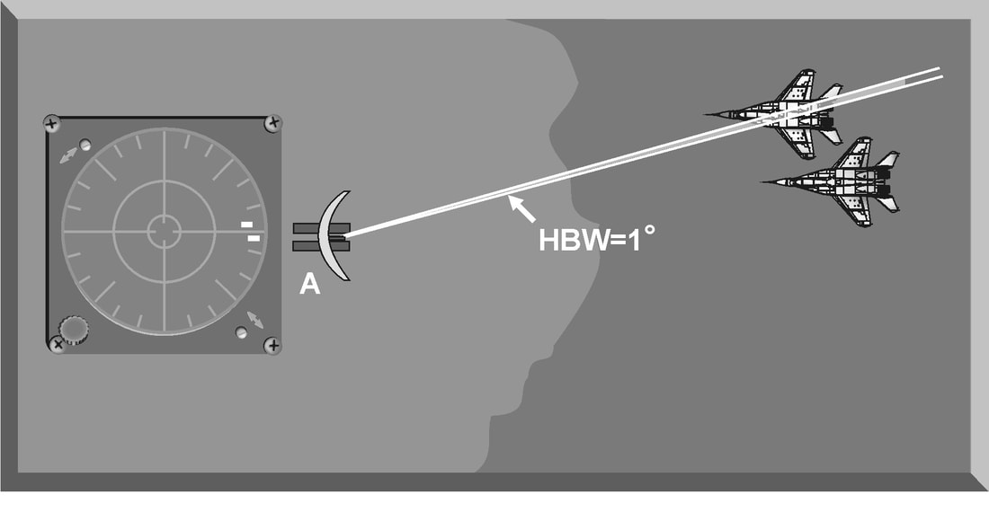
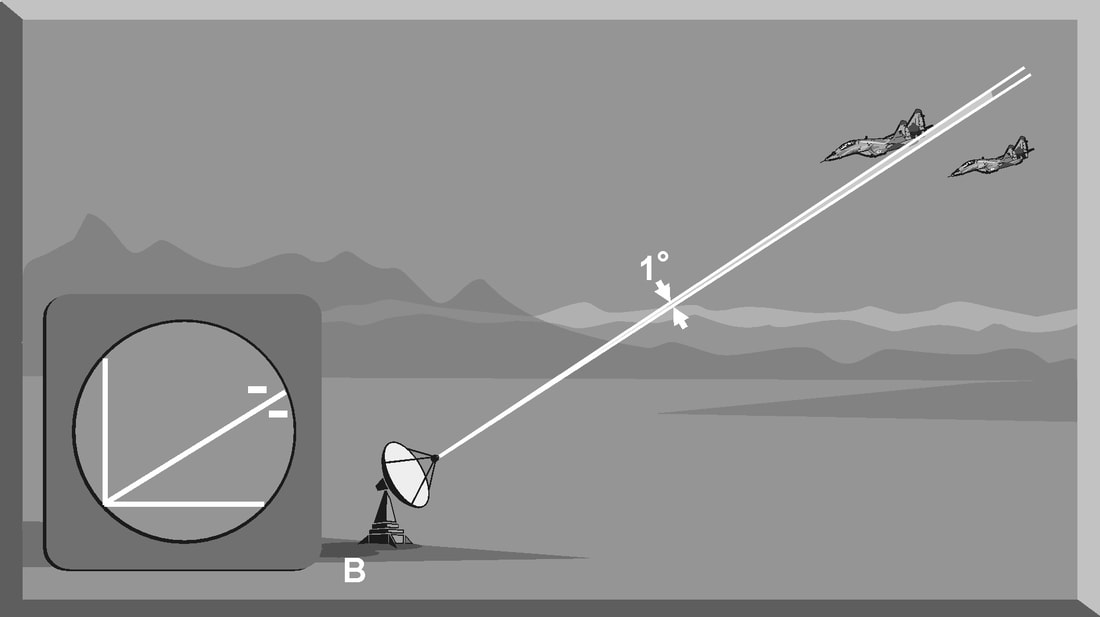
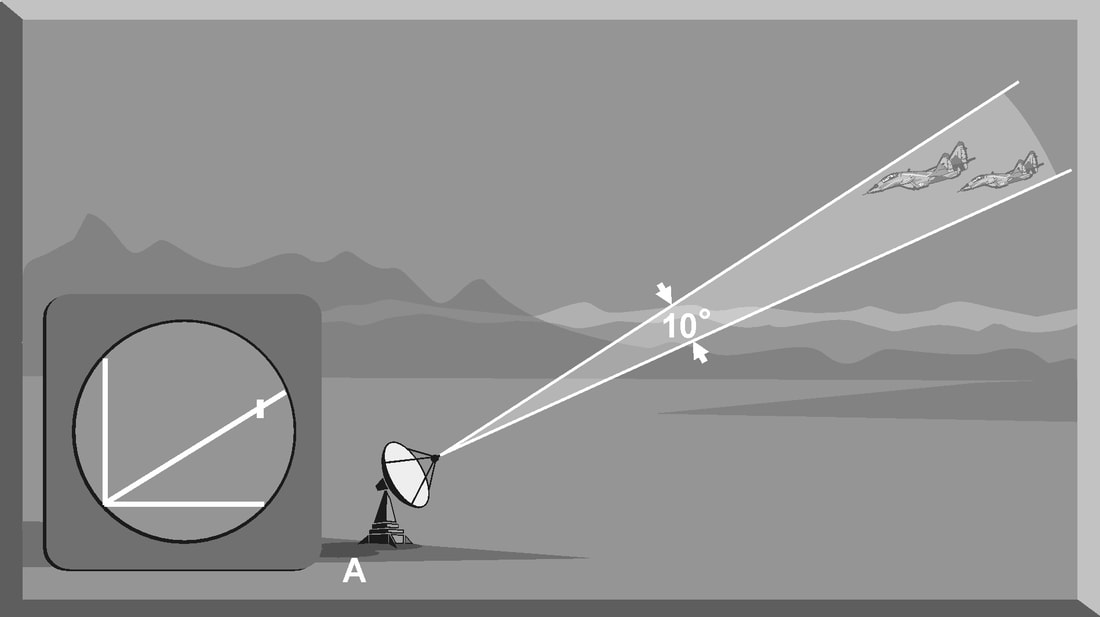
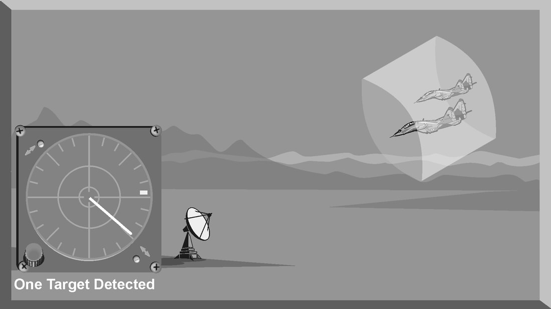
Introduction The primary purpose of radar systems is to determine the range, azimuth, elevation, or velocity of a target. The ability of a radar system to determine and resolve these important target parameters depends on the characteristics of the transmitted radar signal. This chapter explains the relationship of radar frequency (RF), pulse repetition frequency (PRF), pulse width (PW), and beam width to target detection and resolution. Radar range A basic pulse radar system consists of four fundamental elements: the transmitter, the receiver, the antenna, and the synchronizer, or master timer. Transmitter The transmitter, through the antenna, sends out a pulse of RF energy at a designated frequency. The presence of a target is revealed when the RF energy bounces off the target, returns to the radar antenna, and goes into the receiver. The master timer measures the time between the transmission of a pulse and the arrival of a target echo. RF energy travels at the speed of light (c) which is 3 x 10⁸ meters per second. Target range can be computed by using the basic radar range determination equation. Target Range = (measured Time * Speed of light)/2 Another useful measurement is the radar mile, which is the round trip time for an RF wave to travel to and from a target one nautical mile away. In simple terms the time required for a radar pulse to travel a distance of one nauticalmile and then return to the radar receiver. One radar nautical mile is equal to approximately 12.367 μs Measured time = (Target Range *2)/ c = (1853 meters *2) / 300000000 = 12.367 Micro Seconds. Radar timing is usually expressed in microseconds. To relate radar timing to distances traveled by radar energy, you should know that radiated energy from a radar set travels at approximately 984 feet per microsecond. With the knowledge that a nautical mile is approximately 6,080 feet, we can figure the approximate time required for radar energy to travel one nautical mile using the following calculation: A pulse-type radar set transmits a short burst of electromagnetic energy. Target range is determined by measuring elapsed time while the pulse travels to and returns from the target. Because two-way travel is involved, a total time of 12.36 microseconds per nautical mile will elapse between the start of the pulse from the antenna and its return to the antenna from a target. This 12.36 microsecond time interval is sometimes referred to as a RADAR MILE, RADAR NAUTICAL MILE, or NAUTICAL RADAR MILE 1 Radar Kilometer = 6.66 Micro Sec The range in kilometers to an object can be found by measuring the elapsed time during a round trip of a radar pulse and dividing this quantity by 6.66. The range in nautical miles to an object can be found by measuring the elapsed time during a round trip of a radar pulse and dividing this quantity by 12.36. A limitation on radar detection range is the concept of a second time around echo. A second time around echo occurs when a target echo associated with a particular radar pulse arrives at the antenna after another radar pulse has been transmitted. The radar master timer always assumes the target echo is associated with the last pulse transmitted. This makes the target echo ambiguous in range. Example: - Radar pulse A takes 372 microseconds to travel to the target and return. Using the range determination equation, actual target range is 30 nautical miles (nm). However, before the target echo returns to the antenna, radar pulse B is transmitted. The master timer associates the target echo of pulse A with radar pulse B, and calculates a target range of 10 nm. This ambiguous and false range is displayed to the operator. Modern radars are designed with second time around echo as important functional modes, and engineers have developed ways to resolve the ambiguity. Range resolution A critical aspect of range determination is range resolution. Range resolution is the ability of radar to separate two targets that are close together in range and are at approximately the same azimuth. The range resolution capability is determined by pulse width. Pulse width is the time that the radar is transmitting RF energy. Pulse width is measured in microseconds. A radar pulse in free space occupies a physical distance equal to the pulse width multiplied by the speed of light, which is about 984 feet per microsecond. If two targets are closer together than one-half of this physical distance, the radar cannot resolve the returns in range, and only one target will be displayed. The range resolution of the radar is usually expressed in feet and can be computed using Equation Range Resolution = (pulse width *984 ft)/2 It is the minimum separation required between two targets in order for the radar to display them separately on the radar scope. Azimuth Determination The beamwidth of a radar system is the horizontal and vertical thickness of the radar beam. Beamwidth depends on antenna design and is normally measured in degrees from the center of the beam to the point at which the power drops off by half. This half-power point is -3 dB in power drop-off. Beamwidth governs the azimuth and elevation accuracy and resolution capability of a radar system in the same way that pulse width governs radar range accuracy and resolution. In order for a radar system to figure out target azimuth, the antenna must be aligned with a point of reference and pointed at the target during the transmission and reception of several pulses of radar energy. If the antenna is referenced to true North, the azimuth of the target can be measured relative to true North. Azimuth determination is based on the position of the antenna when the target is being illuminated. To provide accurate azimuth determination over a large area, many types of radar employ a narrow beam and scan the antenna in a predictable pattern. The most common scan pattern is a 360° circular scan at a constant rate. The plan position indicator (PPI) radar scope display is normally associated with this scan pattern. As the radar beam sweeps, a target is detected and displayed. The position of the antenna, when the target is displayed, shows the relative azimuth. The azimuth accuracy of a radar system is determined by the horizontal beamwidth (HBW). Consider the following Figure, radar system A has a horizontal beamwidth of 10°. As the beam sweeps, the target is illuminated for as long as it is in the beam. This means that the target covers 10° in azimuth on the PPI scope. Radar system B has a beamwidth of 1°. A target displayed on the PPI scope will cover 1° in azimuth. The narrower the horizontal beamwidth, the better the azimuth accuracy. Azimuth resolution is the ability of radar to display two targets flying at approximately the same range with little angular separation, such as two fighters flying line-abreast tactical formation. The azimuth resolution capability is usually expressed in nautical miles and corresponds to the minimum azimuth separation required between two targets for separate display. Azimuth resolution depends on the horizontal beamwidth of the radar. The radar system in Figure has a horizontal beamwidth of 10°. The two targets are so cIose in azimuth that the return echoes are blended into one return. The radar system in the next Figure has a horizontal beamwidth of 1°. The radar beam not only hits the targets, but passes between them without causing a return. This allows the radars to display two distinct radar returns. A small horizontal beamwidth improves azimuth resolution. Azimuth resolution, in nautical miles, can be computed using Equation Azimuth resolution = (Horizontal Beam width * Range) 60 Notice that this equation is the “60 to 1 rule” used for navigation. A 1°beamwidth will yield a one-mile-wide cell at 60 nautical miles. Elevation determination Since a radar beam is three-dimensional, the vertical beamwidth is the primary factor in determining altitude resolution capability. Altitude resolution is the ability of radar to display two targets flying at approximately the same range and azimuth with little altitude separation, such as two fighters flying a vertical stack formation. The altitude resolution capability is usually expressed in feet and corresponds to the minimum altitude separation required between two targets for separate display. The radar system in Figure has a vertical beamwidth of 10°. The two targets are so close in altitude that the return echoes depicted on the range height indicator (RHI) are blended into one. The radar system depicted in Figure has a vertical beamwidth of 1°.This small beam not only hits the targets, but passes between them without causing a return. This allows the radar to display two distinct targets. Altitude/elevation resolution, in thousands of feet, can be computed using Altitude Resolution = (Vertical beam width * Range)/ 60 Radar resolution cell A radar's pulse width, horizontal beamwidth, and vertical beamwidth form a three dimensional resolution cell (RC) . A resolution cell is the smallest volume of airspace in which a radar cannot determine the presence of more than one target. The resolution cell of a radar is a measure of how well the radar can resolve targets in range, azimuth, and altitude. The horizontal and vertical dimensions of a resolution cell vary with range. The closer to the radar, the smaller the resolution cell. The physical dimensions of a radar's resolution cell can be computed. For a radar with a pulse width of 1 microsecond, a horizontal beamwidth of 1°, and a vertical beamwidth of 10°, the formulas for range resolution, azimuth resolution, and altitude resolution can be used to compute the dimensions of the resolution cell. For example , at a target range of 10 nm, the physical dimensions of the radar's resolution cell are 492 feet in range, by 1000 feet in azimuth, and 10,000 feet in altitude. These figures can be confirmed by using above Equations. Based on these computations, two, or more, aircraft flying a trail formation closer than 492 feet would be displayed as a single target. Two, or more, aircraft flying line abreast closer than 1000 feet would be displayed as a single target. Two, or more, aircraft flying a vertical stack closer than 10,000 feet would be displayed as a single target. This also shows that the shorter the pulse width, the better the range resolution capability of a radar system. The narrower the horizontal beamwidth, the better the azimuth resolution capability. The narrower the vertical beamwidth, the better the altitude resolution capability. Another type of resolution is velocity resolution. For a Doppler radar aircraft flying within the conventional resolution cell described above can be distinguished as separate targets if they have enough speed differentials. Pulse Doppler Velocity Determination To fully understand how a pulse Doppler radar determines target velocity, it is necessary to know more about the pulsed waveform. To generate a pulse modulated wave, a continuous carrier sine wave, like the output from a CW radar, is combined with a rectangular wave, like that of a pulse radar, to produce the pulse modulated waveform. Mathematically, any waveform other than a sine wave is composed of many different pure sine waves added in the proper amplitude and phase relationships. In a pulsed modulated waveform, the sine waves correspond to the fundamental frequency, which is the PRF, and the sum of all harmonics in the proper amplitude and phase. The frequency of the harmonic is the basic frequency plus or minus a multiple of the PRF. Below Figure is a plot of the harmonic content of a pulse modulated waveform operating at a carrier frequency of 2800 megahertz (MHz) with a PRF of 1 MHz. Note the loops of frequencies on either side of the carrier frequency. These are the additions and subtractions of all the frequencies in the rectangular pulse to the carrier frequency. The important thing to remember is that there are many frequencies present, and a pulse Doppler radar must deal with a crowded frequency spectrum. This becomes even more important when one considers the fact that every frequency present will experience a Doppler shift when it is reflected by a moving target. The individual frequencies shown are called spectral lines. For a pulse Doppler radar to accurately measure velocity, it must compare the frequency change, or Doppler shift, between the carrier frequency and the frequency returning from the target. It is a difficult task for the radar to differentiate between the returning carrier and all the harmonic frequencies. The radar differentiates between the returning carrier frequencies and all other harmonic frequencies by using clutter cancellers, or filters, at the known harmonic frequencies. The radar cannot process frequencies cancelled by these filters. The filters create “blind speeds” for the radar. The closer together the spectral lines, the more “blind speeds” the radar will have. Since the position of the harmonics in relation to the carrier frequency is based on PRF, the number of blind speeds can be reduced by changing the PRF of the radar. The higher the PRF, the wider the spacing of the spectral lines and the fewer blind speeds due to selective clutter canceling. However, a high PRF increases the problem of range ambiguities. Most modern pulse Doppler radars employ a medium and high PRF mode. Medium PRF equates to fewer range ambiguities but more blind speeds. High PRF has fewer blind speeds but more range ambiguities To separate the returning target frequency shifts from all other frequencies in the returning waveform, the pulse Doppler radar employs filters to cancel the known harmonic frequency shifts. In addition, the radar cancels out all returns with no frequency shift, which equates to canceling all returns with no movement relative to the radar. However, if the radar has too many clutter filters, this creates multiple blind speeds, and targets will be missed. Basic Radar Equation The basic radar equation relates the range of a radar system to the characteristics of the transmitter, receiver, antenna, and the target. The radar equation provides a means not only to figure out the maximum range of a particular radar system, but it can be used to understand the factors that affect radar operation. In this section, the simple forms of the radar equation are developed, starting with the power density of the transmitting antenna to the power received by the receiving antenna. Power density is the power of a radio wave per unit of area normal to the direction of propagation. The power density generated by a practical antenna can be expressed Power density from Antenna = (PT*G) / (4*pi*r2) PT = Transmitted Power G = Antenna Gain R = Radius of the antenna As the radar beam propagates through space, it arrives at a target at some range (R) from the antenna. As the radar beam travels through space, the wavefront of the beam expands to a very large cross-sectional area, especially in relation to the target dimensions. The power density of the radar beam, across this wide area, at the target, is detailed in the below Equation Power Density at Target = (PT*G) / (4*pi*r2) PT = Transmitted Power G = Antenna Gain R = Range to the Target Since the cross-sectional area of the radar beam is so large, only a small portion of the total power in the beam can be reflected toward the antenna. The rest of the radar energy continues through space and is dissipated, absorbed, or reflected by other targets. The small portion of the radar beam that hits the target is reradiated in various directions. The measure of the amount of incident power intercepted by the target and reradiated back in the direction of the antenna depends on the radar cross section (RCS) of the target. Equation details the power density of the target echo signal reflected back to the radar antenna is below Power Density at Antenna = [(PT*G) / (4*pi*r2)] * [RCS / (4*pi*r2)] PT = Transmitted Power G = Antenna Gain R = Range to the Target RCS= Radar Cross Section As the target echo reaches the antenna, part of the echo is captured by the antenna based on the effective aperture (Ae). Equation details the actual signal power received by the radar system follows. This is one form of the basic radar equation and is the signal strength of a radar return from a specific target at range (R) from the radar. Signal Power Density(S) = [(PT*G*RCS*Ae) / ((4*pi) 2*r4)] PT = Transmitted Power G = Antenna Gain R = Range to the Target RCS= Radar Cross Section Ae = Effective aperture A detailed analysis of this equation is not required to draw some basic conclusions about the factors affecting the detection of an aircraft. If any factor in the numerator, such as transmitted power, is increased by a factor of three, the signal received by the radar will increase by only 30 percent. This clearly shows why radar system operation is characterized by the transmission of megawatts of power and the reception of microwatts of returning power. In addition, this equation shows that the most critical factor in determining radar detection is target range. The maximum radar range (RMAX) occurs when the signal power density received just equals the minimum detectable signal (SMIN) for the receiver. Solving Equation for range, and substituting SMIN, yields the basic radar equation for RMAX for a specific target. This is another form of the basic radar equation. R max = [(PT*G*RCS*Ae) ¼] / ((4*pi) 2* S min)] PT = Transmitted Power G = Antenna Gain R = Range to the Target RCS= Radar Cross Section Ae = Effective aperture 7/27/2022 05:15:47 am
Hi, Team, Thank you for giving information abot the Electronic warfare. In this Blog it is clearly mentioned about the Radar range, Range resolution, Azimuth Determination, Elevation determination, and Radar resolution. And these graphs are very clear and neat it is easy to understand. Thank for you info!!!
Reply
Leave a Reply. |
AuthorPalash Choudhari Archives
June 2021
Categories
All
|
 RSS Feed
