|
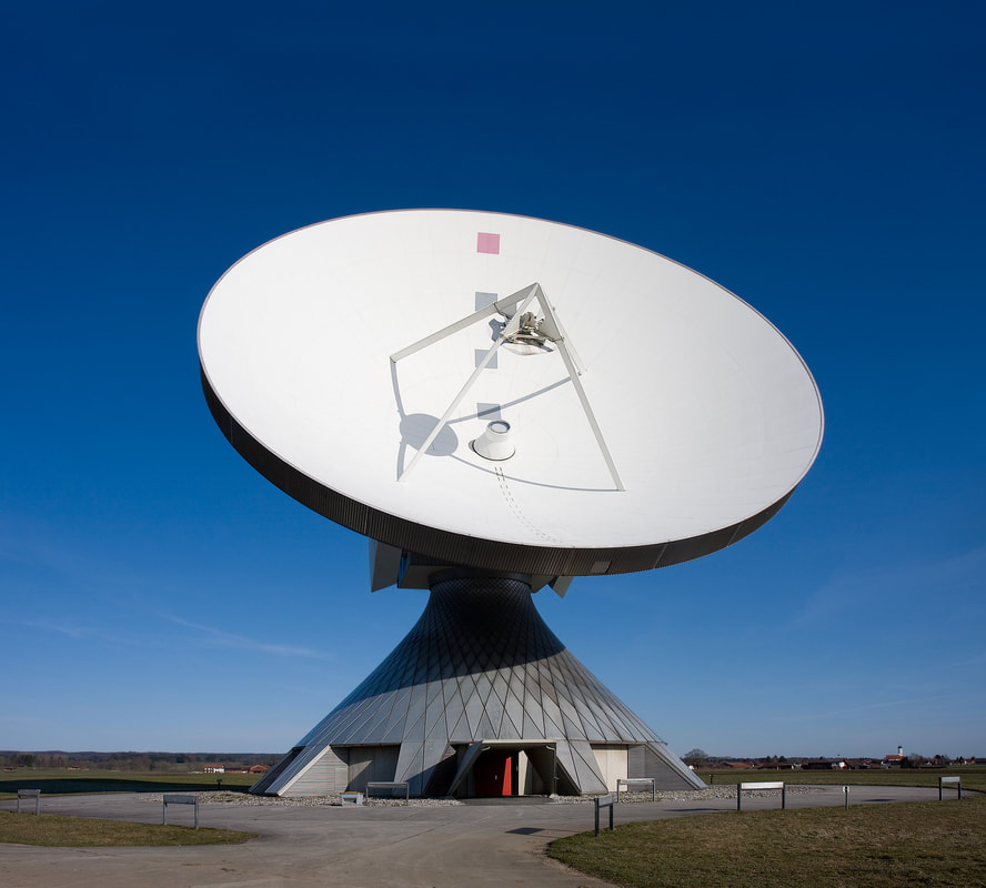
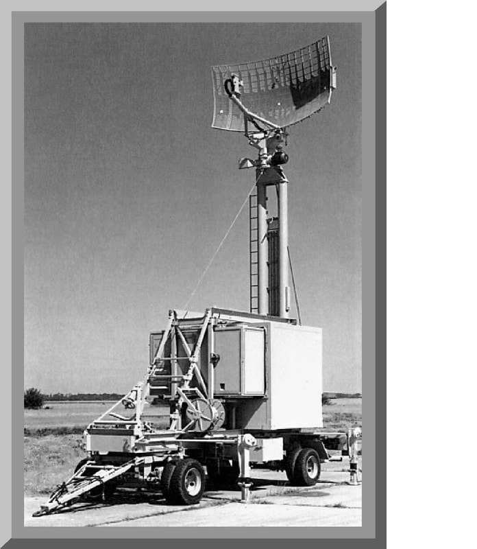
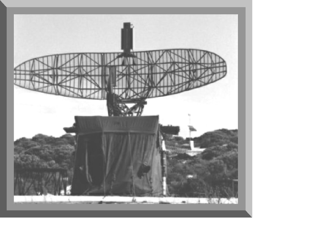
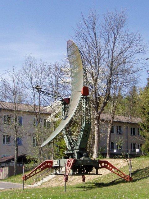
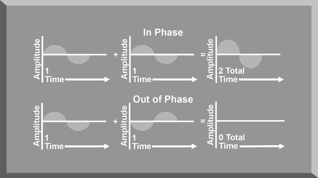
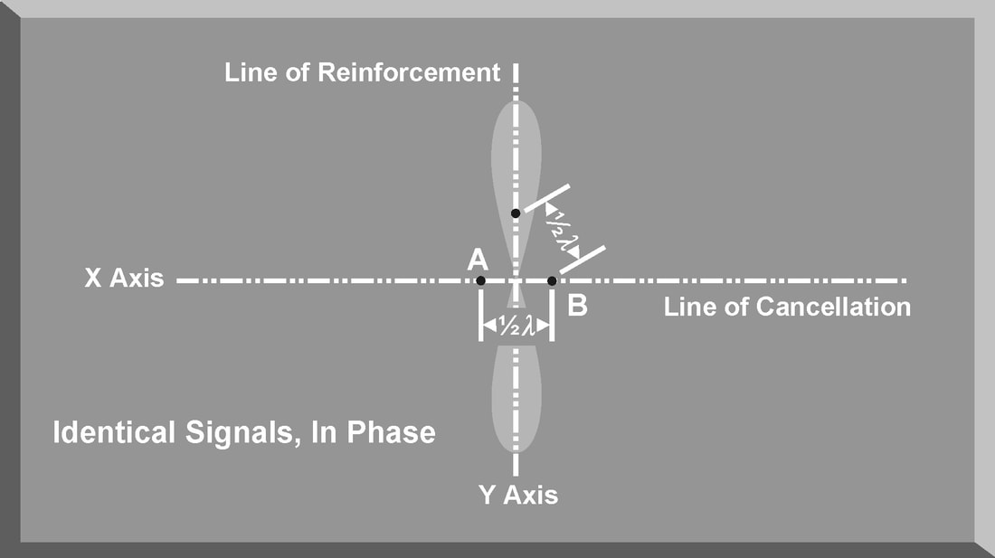
The function of the antenna during transmission is to concentrate the radar energy from the transmitter into a shaped beam that points in the desired direction. During reception, or listening time, the function of the antenna is to collect the returning radar energy, contained in the echo signals, and deliver these signals to the receiver. Radar antennas are characterized by directive beams that are usually scanned in a recognizable pattern. The primary antenna types in use today fall into three categories: parabolic, Cassegrain, or phased array antennas. Additionally, the method radar antennas employ to sample the environment is a critical design feature of the radar system. The scan type selected for a particular radar system often decides the employment of that radar in an integrated air defense system (lADS). The process the radar antenna uses to search airspace for targets is called scanning or sweeping. PARABOLIC ANTENNA One of the most widely used radar antennas is the parabolic reflector. The parabola-shaped antenna is illuminated by a source of radar energy, from the transmitter, called the feed. The feed is placed at the focus of the parabola, and the radar energy is directed at the reflector surface. Because a point source of energy, located at the focus, is converted into a wavefront of uniform phase, the parabola is well suited for radar antenna applications. By changing the size and shape of the parabolic reflecting surface, a variety of radar beam shapes can be transmitted. The antenna depicted in Figure generates a nearly symmetrical pencil beam that can be used for target tracking. Elongating the horizontal dimensions of the parabolic antenna creates a radar antenna called the parabolic cylinder antenna. The pattern of this antenna is a vertical fan-shaped beam. Combining this antenna pattern with a circular scan technique creates a radar system well suited for long-range search and target acquisition. Elongating the vertical dimensions of the parabola creates a radar antenna that generates a horizontal fan-shaped beam with a small vertical dimension. This type of antenna is generally used in height-finding radar systems. Another variation of the basic parabolic antenna includes using an array of multiple feeds instead of a single feed. This type of parabolic antenna can produce multiple radar beams, either symmetrical or asymmetrical, depending on the angle and spacing of the individual feeds. CASSEGRAIN ANTENNA A Cassegrain antenna uses a two-reflector system to generate and focus a radar. The primary reflector uses a parabolic contour, and the secondary reflector, or subreflector, has a hyperbolic contour. The antenna feed is located at one of the two foci of the hyperbola. Radar energy from the transmitter is reflected from the subreflector to the primary reflector to focus the radar beam. Radar energy returning from a target is collected by the primary reflector and reflected as a convergent beam to the subreflector. The radar energy is rereflected by the subreflector, converging at the position of the antenna feed. The larger the subreflector, the closer it can be to the primary reflector. This reduces the axial dimensions of the radar but increases aperture blockage due to the subreflector. A small subreflector reduces aperture blockage, but it must be positioned at a greater distance from the primary reflector. To reduce the aperture blockage by the subreflector and to provide a method to rapidly scan the radar beam, the flat plate Cassegrain antenna was developed. The fixed parabolic reflector is made up of parallel wires spaced less than a half wavelength apart and supported by a low-loss dielectric material. This makes the fixed parabolic reflector polarization sensitive. It will completely reflect one type of linear polarization and be transparent to the orthogonal polarization. The fixed antenna feed, in the middle of the moveable mirror, transmits a radar signal polarized to be reflected by the parabolic reflector. The moveable mirror is constructed as a twist reflector that changes the polarization of the radar signal by 90°. The signal from the feed is reflected by the parabolic reflector to the mirror, which rotates the polarization 90°. This rotation makes the transmitted signal transparent to the parabolic reflector, and the signal passes through with minimal attenuation. The radar beam can be scanned over a wide area by rotating the moveable mirror. A deflection of the mirror by the angle Ɵ results in the beam scanning through an angle of 2Ɵ. The geometry of the Cassegrain antenna is especially well suited for monopulse tracking radar applications. Unlike the parabolic antenna, the complex feed assembly required for a monopulse radar can be placed behind the reflector to avoid aperture blocking. PHASED ARRAY ANTENNA The phased array radar is a product of the application of computer and digital technologies to the field of radar design. A phased array antenna is a complex arrangement of many individual transmitting and receiving elements in a particular pattern. A phased array antenna can, in effect, radiate more than one beam from the antenna by using a computer to rapidly and independently control groups of these individual elements. Multiple beams and computer processing of radar returns give the phased array radar the ability to track-while-scanning and engage multiple targets simultaneously. Phased array radar uses the principle of radar phase to control the individual transmitting and receiving elements. When two transmitted frequencies are in-phase, their amplitudes add together, and the radiated energy is doubled. When two transmitted frequencies are out-of-phase, they cancel each other. Phased array radars use this principle to control the shape of the transmitted radar beam. Phase relationships and antenna element spacing determine the orientation of the transmitted beam. For eg, antenna elements A and B are separated by one-half wavelength and are radiating in-phase, that is, when one is at the positive peak, the other is also at a positive peak. Since the elements are one-half wavelength apart, when the positive peak radiated by A reaches B, B will be radiating a negative peak. As the peaks propagate along the X axis, they will cancel each other out. The total radiated power along that axis will be zero. Along the Y axis, however, the positive peaks from A will add to the positive peaks from B, causing the total radiation along this axis to be at its maximum value. This type of array is called a “broadside array” because most of the radiation is in the direction that is broadside to the line of the antenna array. The computer controlling the phase of the signal delivered to each transmitting and receiving element of a phased array antenna controls the direction and shape of the radiated beam. By shifting the phase of the signals between 0° and 180°, the beam sweeps. This is the basic means of producing an antenna scan. In addition, the amplitude, or power, of the signal applied to each element can be varied to control the sidelobes. This alters the shape of the beam which affects the range capability and angular resolution of the radar. Depicts a variation of the phased array antenna, known as a planar array antenna. A planar array antenna uses transmit and receive elements in a linear array, but, unlike the phased array radar, the elements are smaller and are placed on a movable flat plate. The ability to simultaneously track several targets is one advantage of this type of radar. ANTENNA GAIN The most important characteristic of any type of antenna is antenna gain. Antenna gain is a measure of the ability of an antenna to concentrate energy in the desired direction. Antenna gain should not be confused with receiver gain, which is designed to control the sensitivity of the receiver section of a radar system. There are two types of antenna gain: directive and power. The directive gain of a transmitting antenna is the measure of signal intensity radiated in a particular direction. Directive gain is dependent on the shape of the radiation pattern of a specific radar antenna. The directive gain does not take into account the dissipative losses of the antenna. Directive gain is computed using Equation GD = Maximum radiation intensity / Average radiation intensity The power gain does include the antenna dissipative losses and is computed using Equation Power gain = max radiation intensity/ Radiation intensity of an isotropic antenna The term isotropic antenna describes a theoretical spherical antenna that radiates with equal intensity in all directions. This results in a spherical radiation pattern. The power density for any point on an isotropic antenna is the radiation intensity and can be calculated by dividing the total power transmitted (PT) by the total surface area of the sphere, Power density (Isotropic Antenna) = PT (watts)/ 4*Pie*r2 (Cm2) The radiation pattern of an isotropic, or spherical, antenna would provide neither azimuth nor elevation resolution and would be unusable for radar applications. To provide azimuth and elevation resolution, a practical antenna must focus the radar energy. The power density of a practical antenna differs from the isotropic antenna only in terms of antenna gain (G). Power Density (Practical antenna) = PT*G/ 4*pie*r2 The actual power gain (G) of a practical antenna can be calculated by using Equation G= 4*pie*Ae/lamda Ae= effective area of aperture Lamda = Wavelength of the radar POWER DENSITY
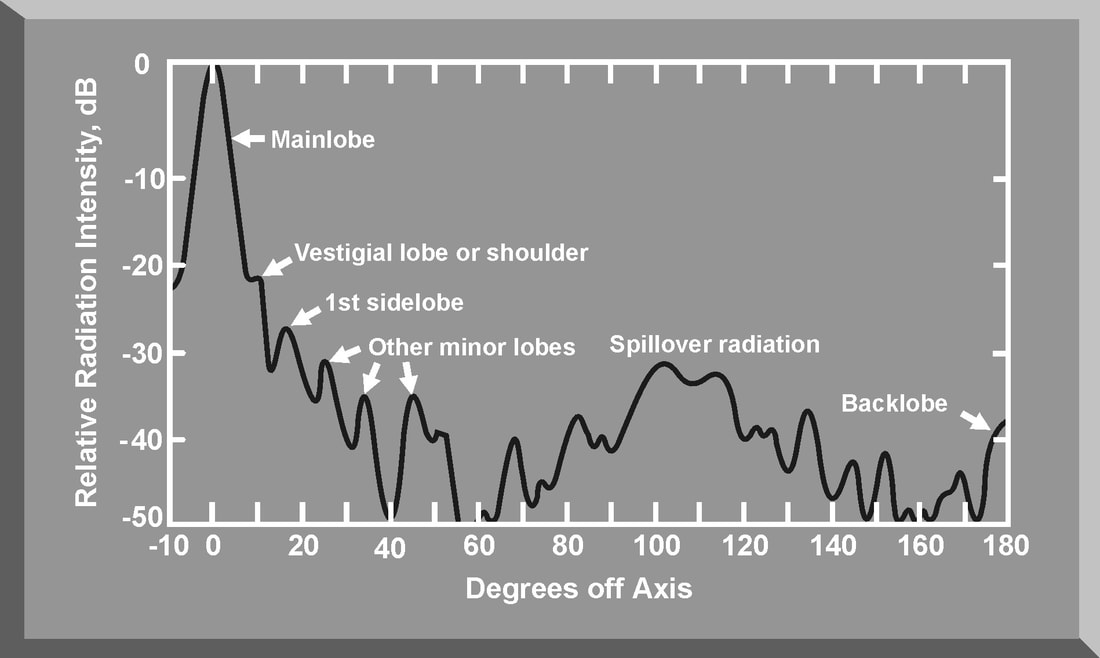
The power density and gain of an antenna are a function of the antenna pattern of a radar system. Figures illustrate the antenna pattern of a typical parabolic antenna. Most of the power density of the radar is concentrated in the main beam. However, since the radar is not a perfect reflector, some radar energy is transmitted in the sidelobes. In addition, there is spillover radiation due to the energy radiated by the feed that is not intercepted by the reflector. Finally, the radar has a back lobe caused by diffraction effects of the reflector and direct signal leakage. Sidelobes and backlobes are all undesirable radiations that adversely affect the maximum radar range and increase the vulnerability of the radar to certain jamming techniques.
Leave a Reply. |
AuthorPalash Choudhari Archives
June 2021
Categories
All
|


 RSS Feed
