|
ELECTRONIC warfare (EW) is the systems approach to the exploitation and control, to the maximum extent possible, of the electromagnetic (EM) spectrum. It is an important capability that can advance desired military, diplomatic, and economic objectives or, conversely, impede undesired ones. The use by an adversary of the EM spectrum for communications, navigation, and radar functions can be challenged by the techniques and technology of EW systems. In a military application, EW provides the means to counter, in all battle phases, hostile actions that involve the EM spectrum—from the beginning when enemy forces are mobilized for an attack, through to the final engagement. EW exploits the EM environment by sensing and analyzing an adversary’s application of the spectrum and imposing appropriate countermeasures (CMs) to hostile spectrum use.  CHARACTERISTICS OF RF RADIATION In order for a radar system to determine range, azimuth, elevation, or velocity data, it must transmit and receive electromagnetic radiation. This electromagnetic radiation is referred to as radio frequency (RF) radiation. RF transmissions have specific characteristics that determine the capabilities and limitations of a radar system to provide these target discriminants, based on an analysis of the characteristics of the target return. The frequency of transmitted RF energy affects the ability of a radar system to analyze target return, based on time, to determine target range. RF frequency also affects the ability of the transmitting antenna to focus RF energy into a narrow beam to provide azimuth and elevation information. The wavelength and frequency of the transmitted RF energy impact the propagation of the radar signal through the atmosphere. The polarization of the RF signal affects the amount of clutter the radar must contend with. The ability of a radar system to use the Doppler effect in analyzing the radar return impacts the velocity discrimination capability of the radar. FREQUENCY The output signal from a typical radar system has several important characteristics that affect the capabilities and limitations of radar systems. The first characteristic considered is usually RF. The frequency of the transmitted signal is the number of times per second the RF energy completes one cycle. The basic unit of measurement is the hertz (Hz). One hertz equals one cycle per second. Most radar has an RF in the millions of hertz. 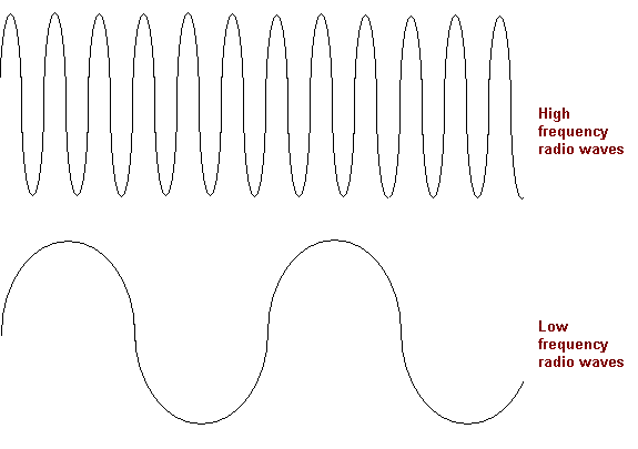 WAVELENGTH A characteristic of any RF signal is wavelength. Wavelength is a measure of the physical distance between peaks of a sine wave propagated in space. Though wavelength is measured in meters, most radar signals have wavelengths measured in centimeters or millimeters. The wavelength of a radar signal can be computed using the equation. Wave length = (Speed of Light/ Radar frequency) 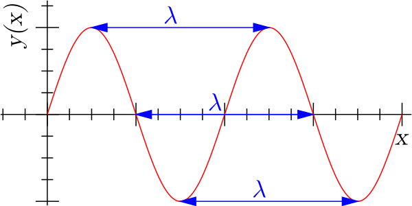 POLARIZATION Another characteristic of a radio frequency wave is polarization. Polarization is determined by the radar antenna and refers to the orientation of the RF wave as it travels through space. There are two types of polarization: linear and circular. Traveling electromagnetic energy has two components: an electrostatic field and a magnetic field. These two fields are always perpendicular to each other and perpendicular to the direction of travel. The polarization of the wave is defined in terms of the orientation to the electrostatic field. Many radar antennas are linearly polarized, either vertically or horizontally. Some radars use circular polarization to improve target detection in rain. Circular polarization can be right-hand, or left-hand orientation. For circular polarization, the direction of the electrostatic field varies with time and traces a circular locus about a fixed plane perpendicular to the direction of propagation. For a right-hand circular polarized signal, the electrostatic vector appears to rotate in a clockwise direction. For a left-hand circular polarized signal, the rotation is counterclockwise. Circular polarization can be visualized by pointing the thumb of either hand in the direction of propagation and curling the fingers in the direction of electrostatic field rotation. The impact of polarization on receivers and transmitters is fairly straightforward. If an antenna is designed to receive a particular polarization, it will have difficulty receiving a signal with an opposite polarization. This situation is defined as cross polarization. The impact of cross polarization on electronic combat can be dramatic. If a radar warning receiver antenna is polarized to receive vertically polarized signals, a threat system employing a horizontally polarized radar signal may not be detected, or may be displayed on the scope well after the threat has acquired the aircraft. In addition, if the jamming antenna on an electronic attack (EA) system is also vertically polarized, it may not be able to jam this system. DOPPLER EFFECT The “Doppler effect” takes advantage of the fact that the frequency of RF waves will be changed or shifted when reflected from a target moving relative to the radar. The shifted frequency of the returning RF wave depends on the movement of the aircraft in relation to the radar. In Figures, fo is the transmitted frequency of the radar, and ft is the frequency of the reflected RF wave from the target. For a stationary target, the frequency of the reflected signal will equal the frequency of the transmitted signal. For a target moving toward the radar, the frequency of the reflected signal will be higher than the transmitted signal. The reflected frequency for a target moving away from the radar will be lower than the transmitted frequency  ELECTROMAGNETIC SPECTRUM The portion of the electromagnetic spectrum that today's electronic combat systems must deal with starts with radio waves and encompasses microwaves, infrared, and a small portion of the ultraviolet region. Communications systems generally operate in the HF, UHF, and VHF regions. Some satellite communications operate in the SHF region. Radars operate in the microwave region, normally from 0.2 – 200 gigahertz. Infrared systems operate in the region just below visible light. 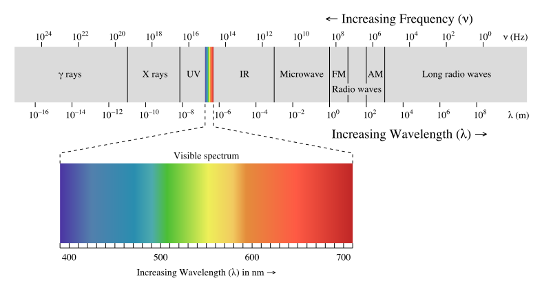 RF PROPAGATION Propagation characteristics of RF energy are profoundly affected by the earth's surface and atmospheric conditions. Any analysis of radar performance must take into account the propagation phenomena associated with RF radiation in a “real world” environment. The most important propagation phenomena include refraction, anomalous propagation (ducting), and attenuation. In a vacuum, RF waves travel in a straight line. However, RF waves propagating within the earth's atmosphere do not travel in a straight line. The earth's atmosphere bends, or refracts, RF waves. One impact of the atmospheric refraction of RF waves is an increase in the line of sight (LOS) of the radar. This increase in radar LOS effectively extends the range of the radar system. Atmospheric refraction of RF energy can also induce elevation measurement errors in radar systems. The refraction of RF waves in the atmosphere is caused by the variation in the velocity of propagation with altitude. Next Section :- Signal Characteristics You can ask any doubt and more info about any topic Picture Courtesy :- Wikipedia , Google Image
jaime giovanni guevara
8/4/2017 02:11:11 am
I love it Leave a Reply. |
AuthorPalash Choudhari Archives
June 2021
Categories
All
|
 RSS Feed
