|
This is the era of 5th gen fighters many nations like China, India, Japan, S. Korea are developing 5th gen aircrafts. The corner stone of 5th gen fighters is stealth they are difficult to detect through radars. Many nations trying to develop systems that can detect stealth aircrafts. How they are going to achieve this the answer is INFRARED. Infrared is electromagnetic waves in the 72-1000 micron range of the spectrum. All matter above absolute zero emits Infrared Radiation. The aircrafts also emits IR (InfraRed) radiation we can use these IR radiation to detect the stealth fighters. This is an attempt from me to describe the very basic physics of IR emission from aircrafts and other related technologies. The IR spectrum covers the range 0.77-1000 micrometer ie; between visible (Red) & microwave radiation. However 3-5 & 8-12 micrometers are used for surveillance and tracking. 3-5 micro meter range is called Medium wave IR (MWIR) & 8-12 micrometer range is called Long wave IR (LWIR). Outside these range the attenuation is high because of CO2 & H2O (vap) scatters & absorb the IR radiation. At low altitudes and cloudy whether condition atmospheric IR transmittance is generally poor. At higher altitudes where CO2 & H2O (vap) concentration is much lower. So IR transmission is better. 3-5 micrometer band has higher peak emission temperature (~450) & better suited for detecting hot spots. Mean while 8-12 micrometer band has lower peak emission temp (~217) & is generally used for detecting emissions from larger surface area with low temperature. The atmosphere attenuates IR to some extent & a bad weather condition also attenuates IR radiation so the range compared to radar is limited. 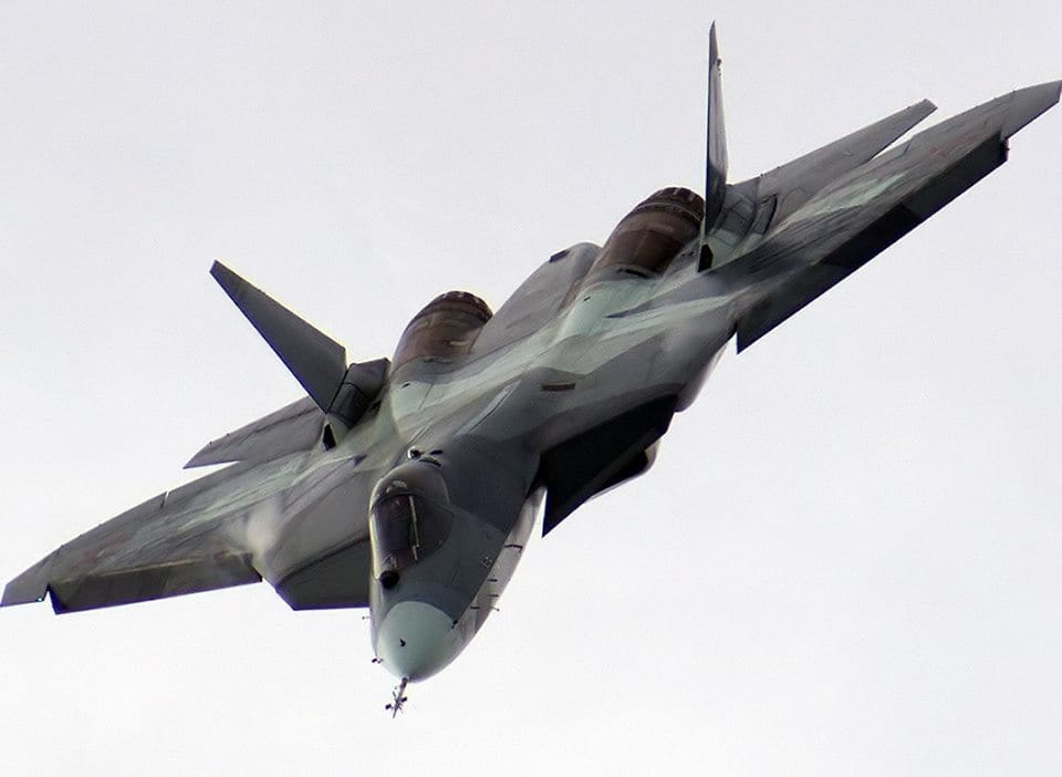 SOURCES OF IR IN AN AIRCRAFT Engine hot parts, exhaust plume, rear fuselage, & aerodynamically heated skin are the important sources of IR emissions in an aircraft. The total IR signature is the sum of aircrafts hot parts emission, aircraft plume emission, skin emission, reflected sky shine, reflected earth shine, reflected sun shine. The discrimination between IR emissions from the aircraft and the surrounding background leads to detection of the aircraft.
The main sources of IRSL (Infra Red Stimulated Luminance, means detection) in aircraft are power plant, nozzle, exhaust plume & airframe. Among these engine is the major source of IR emission. Plume emission is visible from all aspects. The aircraft surfaces produce IR in the 8-14 micrometer band, where as the engine exhaust jet radiates strongly in the 2-6 micro meter bands To obtain the IRSL of aircraft scientists are using mainly 2 methods static engine testing and wind tunnel testing. In static engine test the engine is setup in an outdoor test facility wind tunnel test employs a scaled AC model in wind tunnel 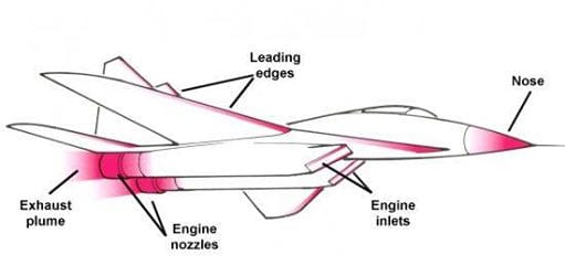 ANALYSIS OF ENGINE & REAR FUSELAGE IR SIGNATURE The aircraft rear fuselage has a large surface area at relatively low temperature, which is primarily heated by the embedded power plant & external aerodynamic heating. Earth shine & sky shine reflections add to the IR emissions from the rear fuselage & become especially important in 8-12 micrometer band for low surface emissivities. The engine casing & nozzle act as grey bodies & emit radiation in all IR bands there by making IR detection easier. After burner flames further enhances IR emissions from the power plant due to much higher temperatures of chemically reacting species & the glowing carbon particles. After burning significantly increases the rear fuselage skin temperature & the temperature of the jet pipe almost doubles while the rear fuselage temperature almost increases by about 70K. Apart from the hot combustion products in the power plant, aerodynamic heating also has significant effect on the rear fuselage skin temp. ANALYSIS OF PLUME IR SIGNATURE The aircraft plume mainly consists of gases like H2O (Vap), CO2, CO & their solid & liquid phases. Amongst these CO2 is the most important IR radiation participating species & other gaseous constituents like O2, N2& NOx are insignificant emitters of IR. The IR radiation from the plume is emitted by the vibration energy of the gaseous species & thermal energy of solid & liquid species. The plume length is several times more than the Aircraft length therefore plume radiation is visible from a much wider angle. The emissivity of a gas volume is a function of temp, pressure molar concentration of gases & the optical path length. The temperature distribution of a plume from a circular nozzle exit is axisymmetric, which simplifies prediction of the plume structure. A mixed turbofan is analyzed for the effect of length of core, spectral optical depth & nozzle size of high aspect ratio nozzles on IR signature characteristics. Increasing the aspect ratio reduces the emissions eg. An aspect ratio of 8 is required to reduce the IR radiation by a factor of 2. The IR emission from rocket plumes is of interest for its role in base heating and engine performance Diagnostics. It is also of importance in strategic functions like early warning, surveillance, acquisition, And tracking. arameters affecting plume IR signature can be grouped into 4 categories ie; engine, vehicle, flight, ambient The engine parameters are mass flow rate, propellant type, mixture ratio (ratio of oxidizer mass to fuel mass), chamber pressure, area ratio & nozzle contour Vehicle parameter include no of nozzle, nozzle spacing, cant angle & base diameter. Altitude velocity & AoA(Angle of attack) are flight parameters & solar azimuth, elevation & earthshine/sun shine/sky shine are ambient parameters. ROLE OF ATMOSPHERE The radiative property of atmosphere depends upon pressure, temperature & concentration of CO2, H2O (vap) & O3. The concentration of water vapor is decreasing proportional to the height & is absent above 10KM & O3 is only present above 20 – 30 KM, other substances such as CH4 & nitrogen oxides also affects IR characteristics but their contribution is small. The transmissivity of atmosphere determines the part of IR radiation emitted by the aircraft that reaches the detectors and its intensity. There are few bands in the IR spectrum where atmospheric transmission is high (Atmospheric windows). IR detectors use these bands to operate. The atmosphere also determines the noise (Background IR radiance), there by determining the contrast & IRSL (Infra Red Stimulated Luminance) of the target. The maximum detection range of IR detector depends on its NEI (Noise Equivalent Irradiance) & the contrast between target aircraft and atmospheric IR radiation. Atmospheric IR radiance is mainly due to the thermal emission by atmospheric gases & scattering of sun light. Atmospheric IR radiance is prominent only in the visible and near infra red bands & observed during the day time, hence it is generally neglected ROLE OF EARTH SHINE Earth shine is the IR radiance from the earth’s surface (It depends on the ground temp and emissivity) that is reflected from aircraft surface and then collected by IR detector. Its estimation is important in the 8-12 micrometer band for AC flying at low level & its effect is insignificant in 3-5 micrometer band  Pictuers supporting the document is not much available and we are very poor in editing so readers please co operate with us and ask if you have any doubts. References
To know more about IRST click on the buttons below
swaroop roy
12/31/2016 12:13:47 pm
my 1st Q. is ,,that infrared beam only detects hot part of aircraft or it detects chilled parts also,,,
Next Generation Weapon tehnology
12/31/2016 10:08:03 pm
Yes , IRST only detects hot parts , cos u know thermal radiation propogate as IR. Leave a Reply. |
AuthorPalash Choudhari Archives
June 2021
Categories
All
|
 RSS Feed
