 IntroductionTejas is a 4+ generation, supersonic, highly maneuverable, multi-role, smallest and lightest in its class contemporary combat aircraft designed for the Indian Air Force designed and developed by DRDO. It is considered ‘game changer’ for India’s air defense preparedness. The LCA has been designed and developed by a consortium of five aircraft research, design, production and product support organizations pooled by the Bangalore-based Aeronautical Development Agency (ADA), under Department of Defense Research and Development Organization (DRDO). Hindustan Aeronautics Limited (HAL) is the Principal Partner in the design and fabrication of the LCA and its integration leading to flight testing. Several academic institutions from over the country have participated in the development of design and manufacturing software for LCA. National teams formed by pooling the talents and expertise in the country are entrusted with the responsibility of the development of major tasks such as development of carbon composite wing, design, design of control law and flight testing. Several private and public sector organizations have also supported design and manufacture of various LCA sub-systems. The LCA design was finalized in 1990 as a small tail-less delta winged machine with relaxed static stability (RSS) to enhance maneuverability performance and a host of other advanced features. A review committee was formed in May 1989 which reported that Indian infrastructure, facilities and technology had advanced sufficiently in most areas to undertake the project. It was decided that the full-scale engineering development (FSED) stage of the programme would proceed in two stages.  Phase 1 - TECHNOLOGY DEMONSTRATION STAGE (TD-1 & 2) The focus in this phase was on ‘proof of concept’. It entailed the development and testing of two technology demonstrator aircraft. These aircraft were called TD-1 and TD-2. The decision to move forward was to be taken after the successful completion of this phase. This would be followed by the production of additional prototype vehicles. There were teething issues during this phase and finally TD-1 flew on 04 January 2001 with Wing Commander Rajiv Kothiyal on the controls. The significance of this golden-day in the history of Indian aviation can be gauged by the fact that the last time an indigenous aircraft had got airborne was almost 40 years ago on 17 June 1961. Phase 2 - ADDITIONAL TESTING PHASE (PV-1, PV-2, PV-3 and PV-5) This phase consisted of additional testing and development of systems using Prototype Vehicles which would lead to the development of the final variant that would join the IAF and the Indian Navy. The first Prototype Vehicle, PV-1 flew on 25 November 2003. By 2005, the Tejas had proven itself in the testing phase and the first order for 20 Series Production aircrafts was placed. A follow on order for an additional 20 SP aircraft was placed in 2010. National Flight Test Centre is the directorate of ADA dealing with flight testing of LCA. All the flight test and aircraft instrumentation related activities are planned coordinated and executed by NFTC which is headed by a Test Pilot from the Indian Air Force. NFTC has Indian Air Force and Indian Navy test pilots and flight test engineers along with the scientists and engineers for instrumentation who are professionally carrying out the flight testing of the LCA.  Aerodynamics Tejas is an aerodynamically unstable tailless compound delta-wing configuration, optimized primarily for maneuverability and agility. Designed to meet the tactical requirements of a modern air force, Tejas is a multi-role aircraft capable of comprehensive air superiority and air defense roles. The aerodynamic design is a culmination of an intense design process involving extensive Computational Fluid Dynamics and Wind Tunnel studies. The tailless, compound delta planform is designed to keep the Tejas small and lightweight. The use of this planform also minimises the control surfaces needed (no tail-planes or fore planes, just a single vertical tailfin), permits carriage of a wider range of external stores, and confers better close-combat, high-speed, and high-alpha performance characteristics than conventional wing designs. Extensive wind tunnel testing on scale models and complex computational fluid dynamics analyses have optimized the aerodynamic configuration of the LCA, giving it minimum supersonic drag, a low wing-loading, and high rates of roll and pitch. Maximum sustained rate of turn is 17 deg per sec and maximum attainable 30 deg per sec. The design incorporates 'control-configured vehicle' concepts to enhance maneuverability. Being a delta, optimal performance is achieved in the higher speed, higher altitude flight regimes with low supersonic & wave drag. Certain low speed and high AoA performance and handling issues inherent to the delta wing design are addressed through both FBW control & certain aerodynamic features which also serve to fully exploit the high lift characteristics of the delta wing. The agility of Tejas in supersonic speeds much better than most of the 4th gen fighters this superior agility gives Tejas better chances in avoiding BVR missiles. The high-set wing of Tejas is essentially a compound delta with CFD optimize camber and twist & a unique low sweep leading edge crank, whose primary function is both the generation and control of concentrated vortices during high Angles of Attack (AoA). The steady downstream flow of strong vortices, re-energizes the boundary layer, stabilizes the air flow, prevents flow separation and creates a suction effect that increases lift. Similar function but better than a large strake or a thin leading edge root extension. The result is superior coefficient of lift and more stable rolling and bending moment characteristics at high AoA. Vortex burst due to vortex instability at high AoA, thus reducing vortex lift a well as certain creating instability and control issues is addressed through the design of the compound wing that controls the strength of the vortices within the AoA regime. Two hollow spills on the ducts on the wing, next to the leading edge, connect with the intake splitter and act as a suction system for boundary layer /vortices control and reducing skin friction drag. Independently actuated, three segment leading edge slats to increase wing area, controllability and lift at high AoA is delayed and the effective lift is increased also allowing for steeper climb angles. The high degree of smooth wing body blending and area ruling produces slender, streamlined, airframe that ensures minimum drag in all flight regimes. Wing shielding for the inlets, serves to even the airflow to the intake at high AoA reduces intake losses and flow distortion. Wind tunnel test on air intake models have been used to used to predict the buzz boundary and pressure performance and thus optimize the diverter configuration of the intake for buzz free operation and higher pressure recovery. Maximum pressure at engine inlet is 260Kpa. Relaxed Static Stability combined with full authority digital fly by wire controls ensures increased maneuverability , margins of safety , flexibility , carefree handling , optimal recovery and reduced weight (albeit within elevon limits ) for stronger pitching moments . The use of artificial stabilization also helps to reduce or eliminate problems associated with tailless designs such as increased trim drag and inability to trim additional pitching moments. The mentioned features with along with the high thrust to weight ratio and large wing area of 38.4 m2 combined with the low overall weight for low wing loading; allow Tejas to achieve truly exceptional flight performance. Design flight performance call for a max AoA of 35 degree, roll rate 270-300degre/sec and sustained load factors of +9/-3.5g, +6g to -2.5g with external sources. Maximum design speed is mach 1.8 at 50000 feet, with sustained supersonic performances at altitudes. Short take off and landing capabilities and touchdown speed of 270Km/H have thus been achieved. Studies into possibly including feature such as thrust vector control, fly-by- Light controls, smart hydraulics etc into future LCA variants have already begun. Similarly the potential implementation of LEVONs and other N-LCA feature on the standard LCA, though, should also see a radical improvement in its flight performance. Specific aerodynamic features provide excellent aircraft performance in a wider flight envelope:
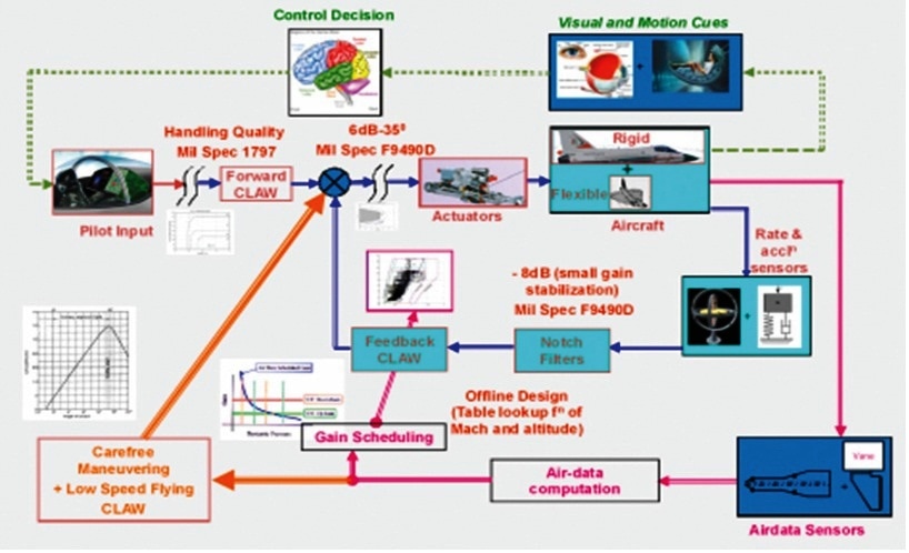
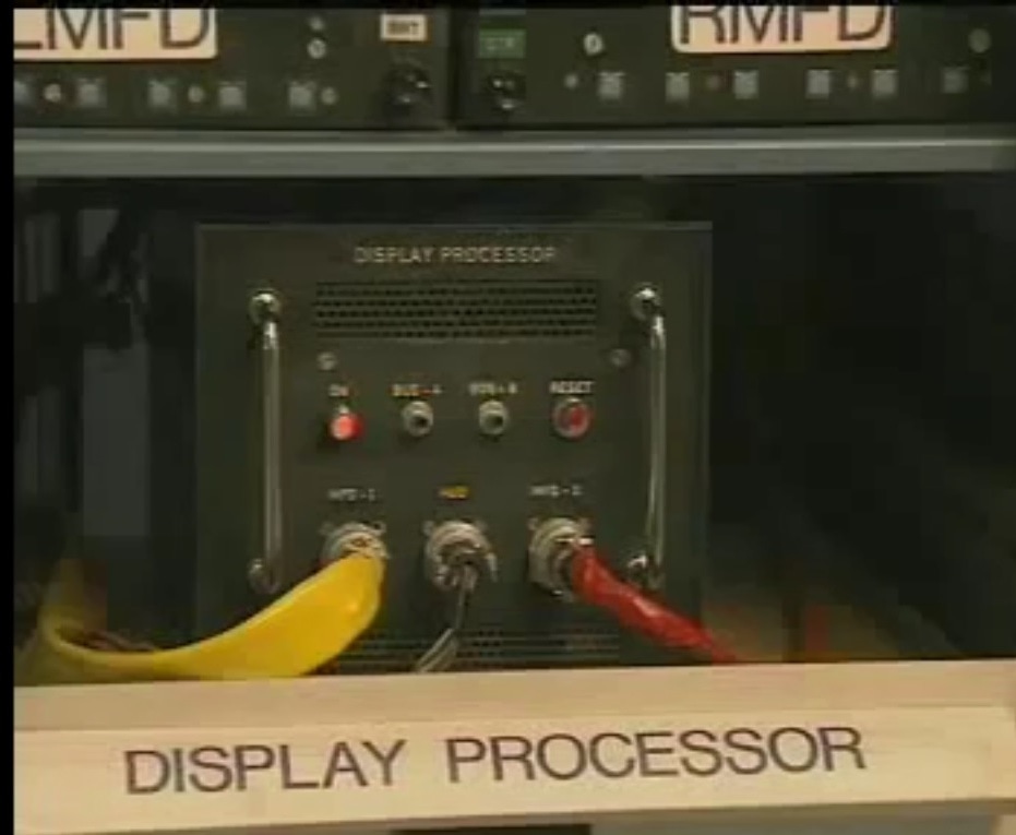
Another feature of Tejas is its Fuel Proportioner . When the aircraft in its mid weight (wing tank empty) condition, the aircraft C.G is most forward. The aircraft is more stable. The maneuvering capability is limited. Hence a passive fuel proportioner introduced in Tejas by varying the diameter of the fuel pipe. With this modification the maximum fuel travel is within ±0.5%. In future the better C.G management is planned by the Active Fuel Proportioner using the motorized valves. A study has been carried out to find the advantage of the passive fuel control by moving the C.G aft from the earlier forward position.  Stealth The RCS of Tejas has been brought down significantly by modifying shape aspects within the limitations set by aerodynamics. Tejas got one of the best RCS value in the entire 4th generation fighters. Publically available figure is 0.5m2. Tejas is a light aircraft. It is the smallest. It is difficult to have a view of it even in a WVR dogfight making it even more lethal and deadly. The smooth upper wing body blending of Tejas gives it enough Stealth to avoid early detection. This kind of upper body blending is only being seen in later generation fighters from sukhoi, rafale, euro fighter typhoon, F-22, PAKFA, and J-20. This high wing body blending is the hall mark of even the fifth gen fighters, reducing the corner reflections from the awacs radars searching from above resulting in lower RCS with missiles and external sores hidden under the wing. Tejas design incorporates a high wing body fuselage blending implemented from behind, resulting in smooth bouncing off of searching radar waves from behind whether they are x band or l band or aesa or mechanical it does not matter. If Tejas flies low hiding its stores no airborne radar will detect it from beyond 120 kms due to 0.3 sq meter rcs (From above, clarification needed). Another stealth feature of Tejas is its Y intake also called bifurcated intake. Engine fan blades are one of the prominent sources of increasing radar cross section. This Y intake buried the jet engine inside the fuselage so no engine parts are visible and thus increases the stealth characteristics. Canopy is another good radar reflector. Radar waves normally enter the cockpit reflects of objects & possibly return to the radar and even the HMD of pilot itself contributes to RCS. To avoid this Tejas canopy is coated with a thin film transparent conductor of Indium Tin Oxide. The coating is thin enough that it has no adverse effect on pilot vision and can reflect the radar waves away from the radar antenna. Almost 90% of the surface of Tejas is made by carbon composites. These composites are much less reflective than metals. So this also makes Tejas,s RCS. Some reports saying India also developing carbon nano tube reinforced carbon composites for future use this will lead to further reduction in RCS India already got patent in RAM coatings. The use of RAM coatings further decreases its RCS dramatically. Better coatings are under researching. Tejas is a single engine aircraft so it is inherently less susceptible to IRSTs compared to twin engine aircrafts. ADA pointed out that they already reduced the IR signature of Tejas. Making it more survivable against heat seeking missiles. 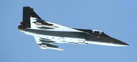 Flight Control System Tejas incorporates a highly reliable quadruplex digital fly-by-wire Flight Control System. Digital fly-by-wire flight control system eases the handling by the pilot. The digital FBW system of the Tejas employs a powerful digital flight control computer (DFCC) comprising four computing channels, each with its own independent power supply and all housed in a single LRU. The DFCC receives signals from a variety of sensors and pilot control stick inputs, and processes these through the appropriate channels to excite and control the elevons, rudder and leading edge slat hydraulic actuators. The DFCC channels are built around 32-bit microprocessors and use a subset of the Ada programming language for software implementation. The computer interfaces with pilot display elements like the MFDs through MIL-STD-1553B multiplex avionics data buses and RS-422 serial links. Tejas is intentionally made longitudinally unstable to enhance maneuverability. The Control laws (CLAW) recover Stability and provide good Handling Qualities to the Pilot. They also provide invariant response with respect to variation in aerodynamics, fuel etc. and facilitate robust performance. The CLAW is carefree and ensures that various aircraft parameters are limited automatically. This enables the pilot to fly the mission without worrying about exceedance of parameters beyond a safe limit. The control laws were developed with the aid of real time simulators at ADE and BAE, UK. As a point of interest, a second series of in-flight simulation tests of flight control software took place in July 1996 at Calspan USA on an F-16D VISTA (variable in-flight stability aircraft); 33 test flights were carried out. One of the comments of the test pilot from the Pentagon was that the F16 flies better with LCA control laws. Tejas performs an automatic Pilot (initiated) Built In Test (PBIT) of the system after engine start. This required a button to be pressed by the pilot after which the flight control computer took over and ran through a pre-programmed sequence of tests at the end of which a green GO lamp flashed in the cockpit. it take about a minute.( All aircraft fitted with fly-by-wire flight control systems have this feature). 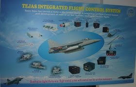 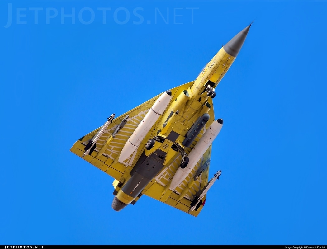 The unstable configuration of LCA demands a highly efficient Integrated Flight Control System (IFCS) to fly the aircraft. Control law resident in the flight control computer synthesizes inputs from pilot's stick and rudder pedals with flight parameters from inertial and air-data measurements to generate commands to the actuators that move various control surfaces. The design of the control law is evaluated using real-time flight simulator for acceptable flight handling qualities. The IFCS ensures stability, agility, maneuverability and carefree handling over the entire operating envelope of LCA. The Digital Flight Control Computer (DFCC) is the heart of IFCS. It hosts 4 computing channels each powered by an independent 28V DC power input from the aircraft. The four channels are identical and each has one digital module which is the main computing unit for control law and redundancy management, three analog boards and one power supply board, all housing in a single LRU. A high speed serial link connects the four channels under the control of redundancy control software performing system failure detection and control reconfiguration. The digital modules also provide MIL-STD-1533B and RS -422 interfaces to various sub systems including the air data transducers, flight test panel, crash data records and so on. The DFCS features extensive built in test, recording and extensive built in test, recording and extensive signal monitoring. The DFCC receives signals from quad rate, acceleration sensors, pilot control stick, rudder pedal, triplex air data system, dual air flow angle sensors, etc. The DFCC channels excite and control the elevon, rudder and leading edge slat hydraulic actuators. The computer interfaces with pilot display elements like multifunction displays through MIL-STD-1553B avionics bus and RS 422 serial link. The complete air-data system is triplex redundant while rate sensor and accelerometer assemblies are quadruplex redundant. A solid state crash data recorder (SSCDR) records the aircrafts analog and discrete flight parameters along with the voice and audio transactions. The quadruplex redundant architecture without mechanical backup has evolved to meet the fail operate fail-safe requirement. The Tejas digital FBW FCS also uses quad redundant electrical power supply dual redundant hydraulic power supply and meets the stringent PLOC requirement of 0.1 failures in million flights. Provisions for the growth of hardware and software in the avionics and flight control system, available in LCA, ensure to maintain its effectiveness and advantages as a frontline fighter throughout its service life. For maintenance the aircraft has more than five hundred Line Replaceable Units (LRSs), each tested for performance and capability to meet the severe operational conditions to be encountered. 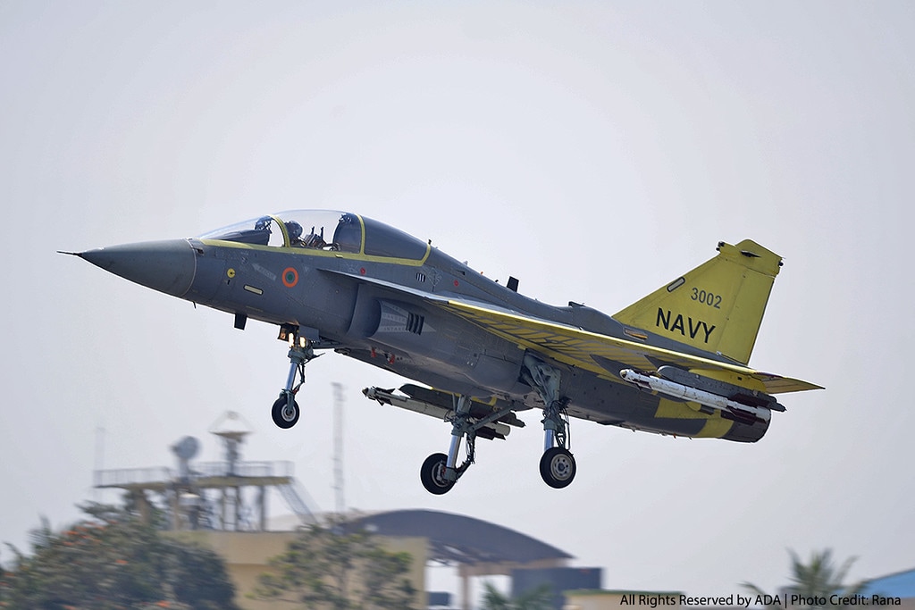 The control laws were developed with the aid of real time simulators at ADE and BAE, UK. As a point of interest, a second series of in-flight simulation tests of flight control software took place in July 1996 at Calspan USA on an F-16D VISTA (variable in-flight stability aircraft); 33 test flights were carried out. One of the comments of the test pilot from the Pentagon was that the F16 flies better with LCA control laws. 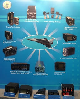  FCS Sensors Quad redundant inertial-based rate sensor assembly RSA is used for the pitch roll and yaw rate sensing Similarly a quad redundant inertial-based acceleration sensor assembly ASA is used for acceleration sensing. The ASA and RSA LRUs have the required electronics to facilitate pre-flight pilot initiated and continuous built-in-test BIT. The air data sensors consist of angle of attack, angle of sideslip, vanes static pressure total pressure, and total temperature probe. The airdate sensors have built in de icing capability and the de icing current is sensed using an indigenously developed DCSU. FCS Actuators LCA is equipped with quadruplex digital Fly-By-Wire Flight Control System. The maneuverability of the LCA is controlled by 13 Flight Control System Actuators. ADA, in order to combat the US sanctions, had taken up (May 1998) the task of indigenizing the flight control system actuators for LCA. A committee was set up (May 1998) with participation of Control system experts from DRDO, ISRO, HAL and ADA. Vikram Sarabai Space Research Centre (VSSC), Thiruvananthapuram was assigned (September 1998) the task of developing some of the flight critical components of the actuators viz., Elevon and Rudder actuators under the name ‘Development and Advanced Linear Actuators (DALIA)’. VSSC was to pass on the Intellectual Property Rights (IPR) to the Nodal Agency, HAL for productionisation. A consortium consisting of HAL, MTAR Hyderabad, Godrej Mumbai was formed (May 2006) for productionisation of the actuators at HAL. Subsequently, HAL Board approved (November 2007) establishment of assembly and test facilities at HAL Accessories division, Lucknow for manufacture of the Actuators. The Tejas digital FBW FCS includes direct drive valve DDV -based primary actuators and EHSV-based secondary actuators. The primary actuators are used for elevon and rudder control surfaces and secondary actuators are used for leading edge slat (LES) and airbrake control. The primary and secondary actuators have the required electronics to facilitate pre-flight pilot initiated and continuous BIT. Control Law Tejas is intentionally made longitudinally unstable to enhance maneuverability. The instability level depends on the flight conditions like Mach number, altitude, AoA etc., and also on the aircraft configurations. The relaxed stability is artificially recovered using dynamic feedback of various aircraft and flight parameters. Processed pitch rate, normal acceleration, AoA, air speed information along with pilot stick trim inputs drive the symmetric Elevon surfaces for achieving the required pitch axis stability augmentation and response shaping Similarly the processed roll rate yaw rate lateral acceleration angle of side slip AoSS along with roll stick rudder pedal input drive asymmetric Elevon and rudder surfaces for achieving the required lateral and directional response shaping velocity vector roll directional stability enhancement etc The active control technology-based control laws automatically reconfigure in flight either for AoA demander for normal acceleration demand based on the flight condition. The Control laws (CLAW) recover Stability and provide good Handling Qualities to the Pilot. They also provide invariant response with respect to variation in aerodynamics, fuel etc. and facilitate robust performance. The CLAW is carefree and ensures that various aircraft parameters are limited automatically. This enables the pilot to fly the mission without worrying about exceedance of parameters beyond a safe limit. The control laws were developed with the aid of real time simulators at ADE and BAE, UK. As a point of interest, a second series of in-flight simulation tests of flight control software took place in July 1996 at Calspan USA on an F-16D VISTA (variable in-flight stability aircraft); 33 test flights were carried out. One of the comments of the test pilot from the Pentagon was that the F16 flies better with LCA control laws.  DFCC Digital Flight Control Computer The Digital Flight Control Computer (DFCC) is a quad redundant flight critical computer based on Intel 80960 32 bit RISC microprocessors. Each of four identical channel consists of one digital module, three no’s of analog modules and one power supply module. They are housed in a single chassis of 1 ATR (long). High speed serial Cross Channel Data Link (CCDL) connects those four channels. The redundancy management software performs failure detection of system and control reconfiguration. The digital module is the core of the DFCC unit and it consist of a main computing unit for control law and redundancy management, MIL-STD-1553B and RS 422 interfaces DFCC to different subsystems like Air Data Computer (ADC), Get-U-Home panel (GUH), Flight Test Panel, Crash Data Recorder(CDR) etc. the analogue modules in each channel provide drive/interfaces for all Flight Control System related items in the aircraft like Primary and Secondary Actuators , Sensors , Cockpit Controls and Indicators . The power supply module provides DC power to internal circuits and sensors units like RSA, ASA, ADT, LVDT and actuators. Provision is made in the design or extensive signal monitoring and Built In Test and recording. Each channel has a transputer based high speed serial XILINX for real time DMA, interfaces for on-ground testing/debugging and special purpose ASIC for I/O interfaces. The DFCC incorporates state of the art technology for chassis; printed wiring boards, board assembly and front panel inter connection with the motherboard through flex circuitry. DFCC has a dip-brazed chassis, and double walled construction for forced air-cooling. It is designed to operate up-to 1 hour failure in supply of cooling air. The printed wiring boards are 10 to 22 layer type with heat sink bonding for thermal management. The average Power dissipation is around 300 watts and the unit weighs 27.8Kgs. The DFCC is qualified through multi-level testing such as assembly validation through In-Circuit –Testing, SRU level testing using Automatic Testing Equipments, and LRU level ATP using high performance test equipment i.e. Engineering Test Station (ETS) to ensure confirmation of performance . The unit meets all the environmental test standards specified for installation on military aircraft.  Cockpit The term Glass Cockpit refers to a modern cockpit in which all the round dialed electro-mechanical instruments have been replaced with Multi-Function Displays (MFDs) and a Head Up Display (HUD). A glass cockpit uses several displays driven by flight management systems, which can be adjusted to display flight information as needed. This simplifies aircraft operation and navigation and allows pilots to focus only on the most pertinent information. An advanced cockpit enhances the comfort level of pilots. The new generation glass cockpit of Tejas comprises Multi Function Displays (MFD), Head Up Display (HUD) and Stand by Instrumentation System driven by Open Architecture Mission and Display Computer. This provides effective Human Machine Interface (HMI). The advanced utility and health management system provides system health and warnings to the pilot through an Open Architecture Computer (OAC). The MFDs are color Active Matrix Liquid Crystal Displays (AMLCDs) Information required by the pilot to take-off, navigate, perform his operational mission, deliver his weapons, cope with enemy threats, return to base and land is gathered by sensors on board the aircraft, processed by a mission computer and then displayed on the MFDs and HUD. Main cockpit displays of Tejas Technology demonstrators comprise of two Multi Function Displays (MFD) and an indigenously developed Head Up Display (HUD). System inputs are through a Multi Function Keyboard (MFK), a Multi Function Rotary (MFR) switch and an HUD mounted Up Front control Panel (HUD-UFCP). The production version will have three MFDs and two Smart Standby Display Units (SSDU), with a Multi Function UFCP (MF-UFCP) combining the functions of MFK, MFR and HUDUFCP. 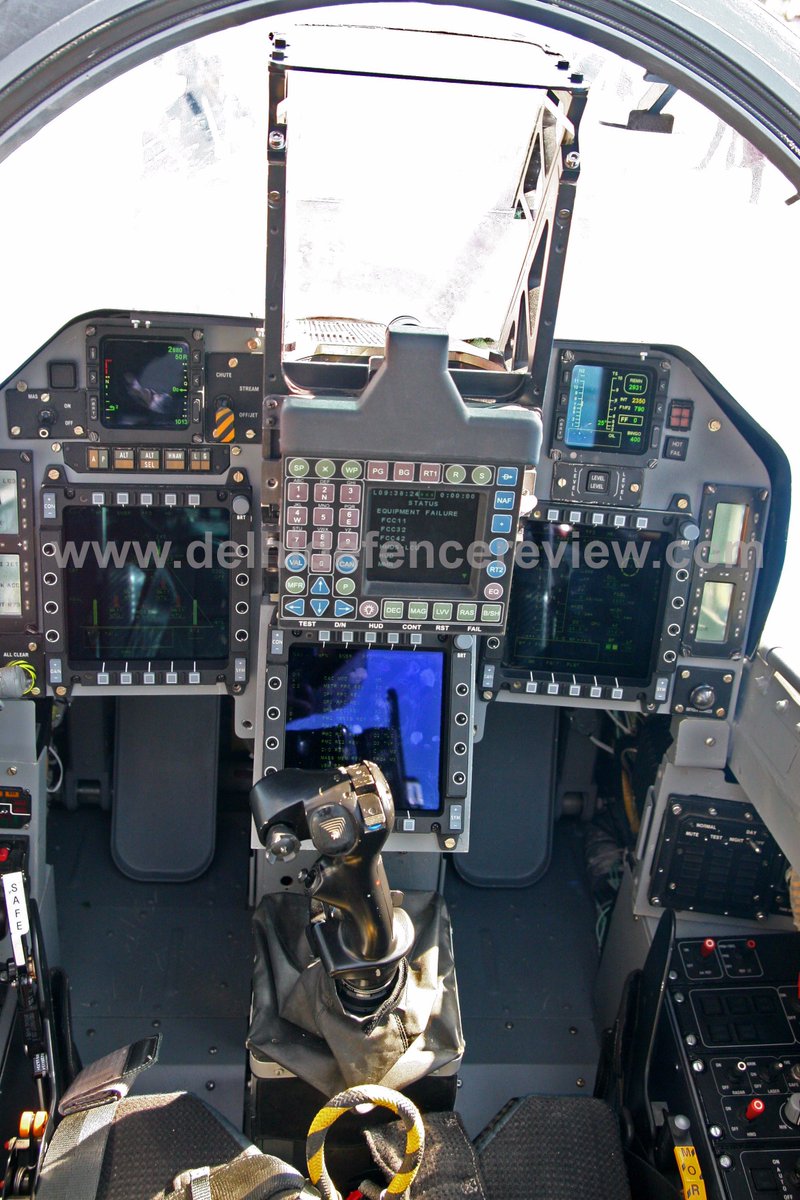 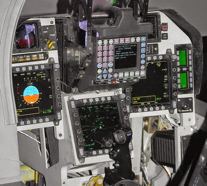 Head Up Display Head-Up Display (HUD) is an essential aid to the pilot of aircraft, especially fighter aircraft. It is a transparent display that presents data without requiring the pilot to look away from his usual viewpoint. The information is projected on to the display surface which is usually referred to as the beam combiner, through a combination of special projection technology, optical assembly and display source. HUD displays flight information such as altitude, airspeed, angle of attack, navigation, weapon aiming and other flight information in collimated form so that the pilot is able to view the information with his head "up" and looking forward, instead of looking down on other instruments mounted in the cockpit. It can also be used to adequately overlay imagery that has a physical relation to the real environment, which makes the information easier to apprehend, such as the runway symbology under poor weather conditions. An indigenous HUD was developed for Tejas by CSIO, indigenous HUD replaces the imported HUD, and it has a larger field of view, three times the brightness, higher redundancy and is noiseless since the design does not call for cooling fan. Reduced noise levels in cockpit with improved system performance & reliability. CSIO scientists had initiated the HUD project in 1992 and developed their unit from scratch. Vital information about the aircraft, and information about altitude, pressure etc, are superimposed on the pilot's viewing window. This means the pilot does not have switch from watching a bank of instruments to the outside world. The Indian HUD, claimed to be superior to similar systems in the international market, can also be used in aiming missiles and guns during combat. The technology is now being modified for the Sukhoi, Jaguar and MIG-27 aircraft. Indigenization of HUD saved lot of foreign currency . 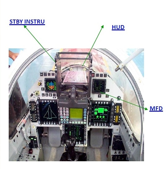 HUD interfaces electronically with Open Architecture Computer (OAC) of the aircraft and generates deflection signals i.e. symbology and characters. The HUD accepts these deflection signals and converts them into the optical image seen by the pilot. CSIR - Central Scientific Instruments Organization, Chandigarh developed bore sighting system for LCA HUD. Bore Sighting System (BSS) is required to harmonize the Mounting Tray (MT) used for mounting Head Up Display in the cockpit of an Aircraft. The BSS substitutes the actual HUD for the purpose of aligning the MT with reference to the Aircraft axis (Fuselage Reference Line - FRL). Once the tray is harmonized, the interchangeability of HUD is ensured within specified tolerance of 1 mRAD. Installation and harmonization of the MT is carried out with the help of a Harmonization Board placed at a distance of 25 meters (approx.) from the design eye position. In the naval variant of the HUD, an electro-optical instrument installed above the cockpit’s instrument panel, is different from the other versions as the environmental and technical specifications vary according to operating requirement. The primary difference between the ship-borne and land-borne versions is the vertical field of view. The pilot of a naval aircraft should also be able to see the deck of the ship, which is much shorter than conventional runways, from approach and take-off angles that are different while operating from airfields. Also, the HUD for naval aircraft has to cater to high radiation levels, which are five times higher on a ship than on the ground. Besides the cockpit configuration of the air force and naval aircraft being different, the onboard systems for naval aircraft have to be more rugged to cater to the harder landings on ships. 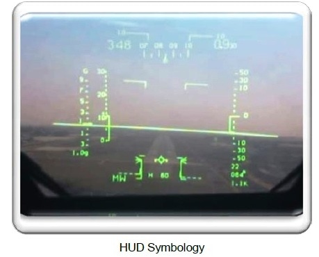 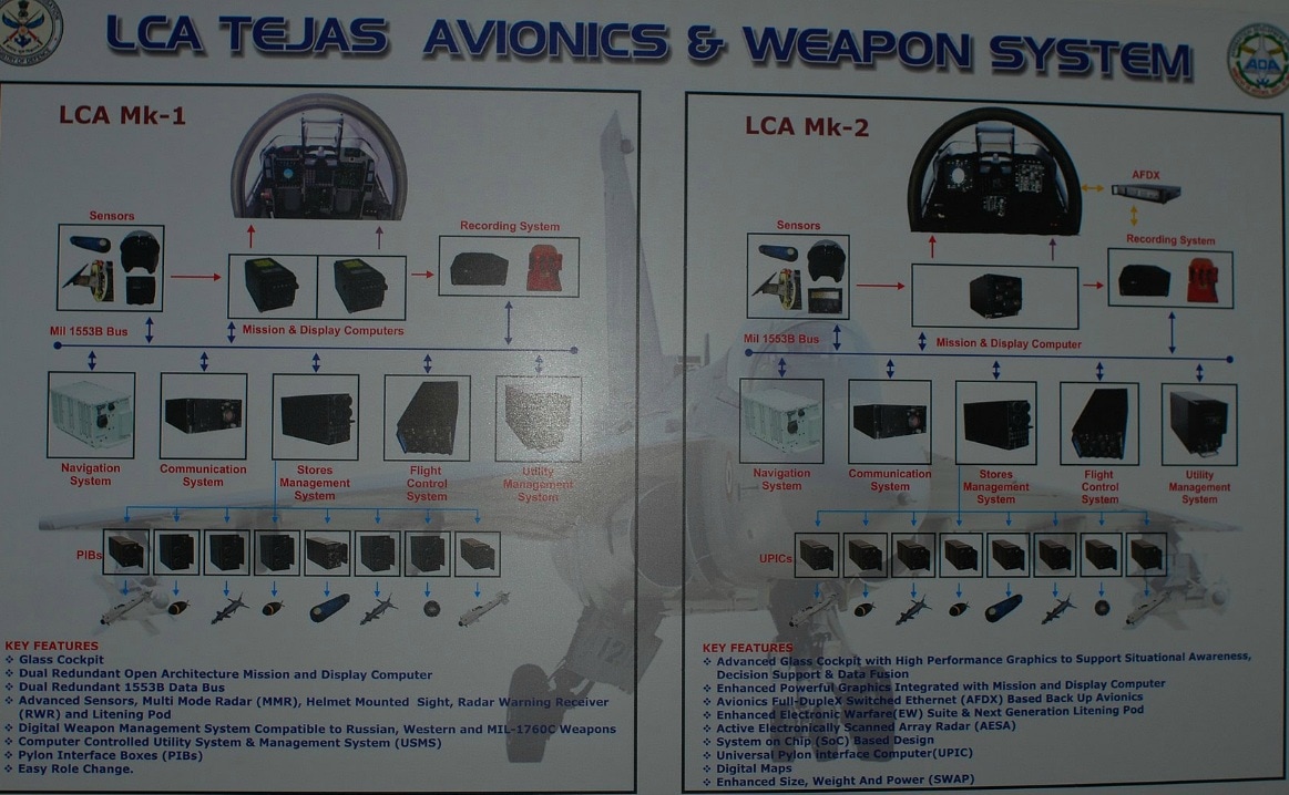 Avionics LCA avionics system has a top down design and has made use of Line-replaceable unit technology, ensuring smooth co-ordination & the minimum degree of interdependence. LCA Avionics was designed, with three 1533B serial buses & two centralized 32-bit, high throughput mission computers, including a communications subsystem, a mission subsystem, a self defense system & a guidance and flight system. In addition, the cockpit includes an environmental control system developed by Spectrum Infotech of Bangalore. The avionics suite has an integrated utility health-monitoring system, ground proximity warning system, terrain referenced navigation system, instrument landing system, global positioning system, stores management system. Accurate Navigation and weapon aiming information on the HUD helps the pilot achieve his mission effectively. The MFD provide information on engine, hydraulics, electrical flight control & environmental control system on a need to know basis along with basic flight & tactical information. Dual redundancy display processors (DP) generate computer –generated imagery on these displays. The pilot interacts with the complex avionics system through a simple multifunction keyboard, function & sensor selection panels. Tejas avionics has an Open Architecture Computer (OAC) designed and developed by ADA, combines the functions of earlier mission computer, display processor, video switching unit, mission preparation and retrieval unit. It is designed based on open system interfaces standards, which provides interoperability, scalability, and portability. OAC drives three multi-function displays, HUD and the helmet-mounted display. This open architecture design will allow the designers to continuously adapt and upgrade Tejas to meet the challenges of modern warfare. A helmet-mounted display and sight (HMDS) is also included, while the hands-on throttle and stick control system minimizes pilot workload and maximizes situational awareness. A ring laser gyro (RLG)-based inertial navigation system (INS), provides accurate navigation guidance to the pilot. An advanced electronic warfare (EW) suite enhances the aircraft survivability during deep penetration and combat. Secure and jam-resistant communication systems, such as IFF, VHF/UHF and air-to-air/air-to-ground data link are provided as a part of the avionics suite. All these systems are integrated on three 1553B buses by a centralized 32-bit mission computer (MC) with high throughput which performs weapon computations and flight management, and reconfiguration/redundancy management. Reversionary mission functions are provided by a control and coding unit (CCU). Most of these subsystems have been developed indigenously. 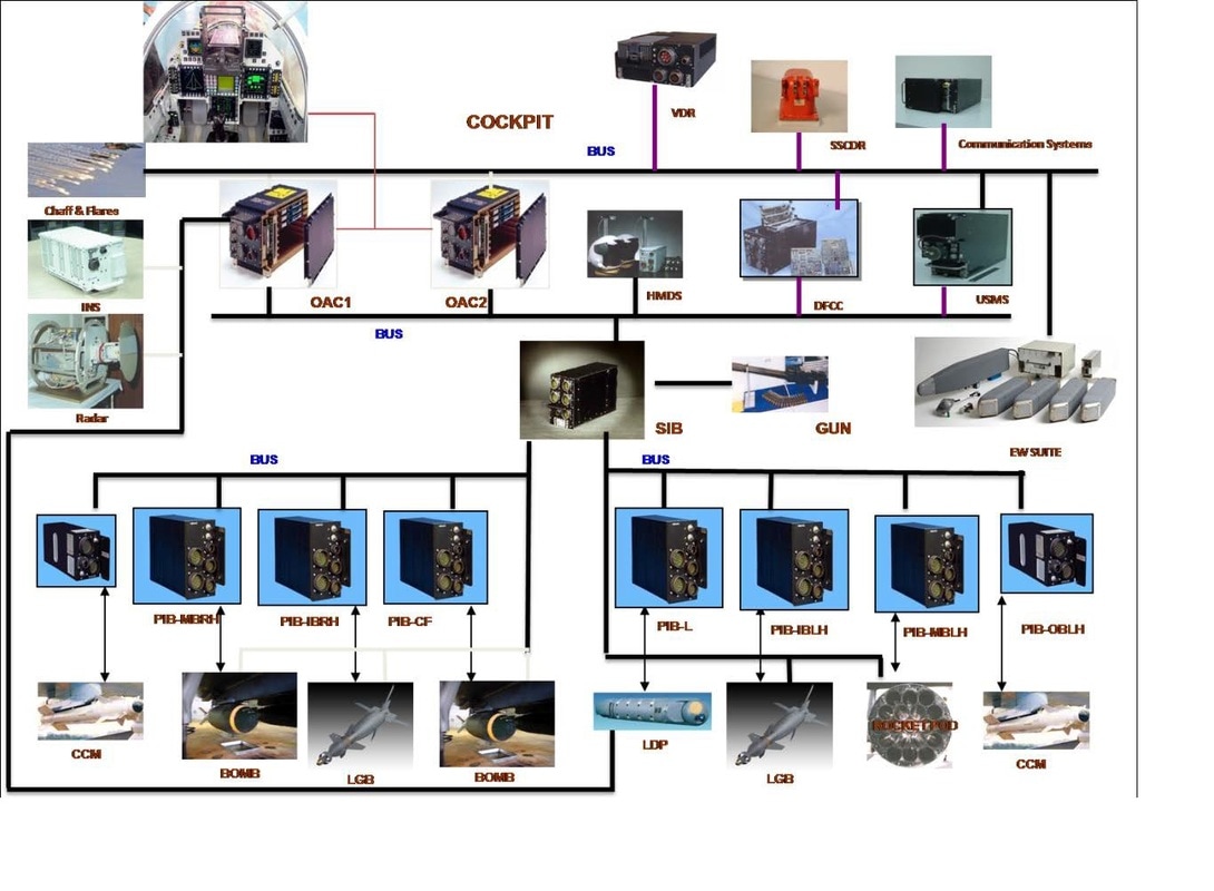 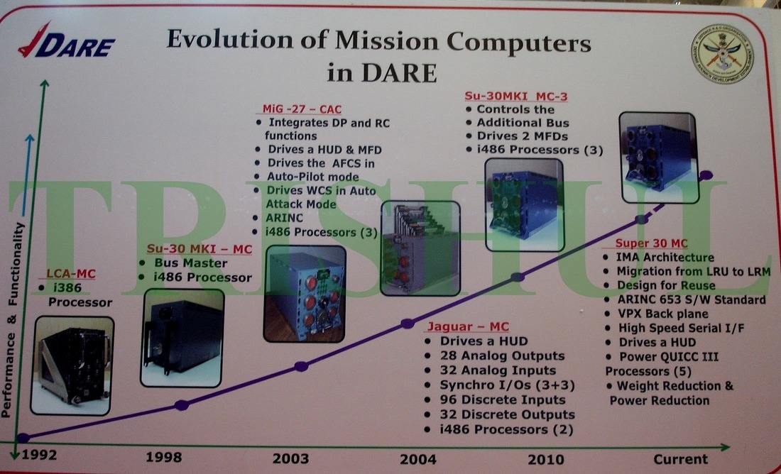 Major components of Tejas Avionics
   FUNCTIONS OF LCA AVIONICS AND WEAPON SYSTEM The major functions performed by the LCA Avionics and Weapon System are:
In the LCA, a number of utility system management systems (USMS) are integrated with the AWS. These systems are for fuel/oxygen management, engine health monitoring, environmental control system management etc. The above mentioned functions are achieved through integrated functioning of the Mission Computer, sensors, controls, displays and the weapon systems - all software driven and in real time mode. AWS SOFTWARE DEVELOPMENT PROCESS An analysis of the Air Staff Requirements (ASR), the LCA mission profiles and the system requirements in each profile led to the definition of AWS requirements. An analysis of these requirements then led to AWS design. The first step in the design was the generation of AWS Broad specifications. The next step was the generation of the AWS functional architecture and the Global specification of each Operational or mission function. Each Global specification describes completely a specific operational function from the Pilot’s point of view. It includes operation of Pilot’s controls, symbologies, warnings etc. AWS FUNCTIONAL ARCHITECTURE The definition of the AWS functional architecture involved:
The LCA AWS functions have been broadly classified into
  MISSION COMPUTER (MC) FUNCTIONS The MC is the manager of the LCA AWS and performs the following functions:
The MC hardware consists of a dual 80386-based computer with dual port RAM for inter-processor communication. MC SOFTWARE DEVELOPMENT OVERVIEW DEVELOPMENT RESPONSIBILITY The MC software has been jointly developed by ADA, HAL, ASIEO and two private sector companies, M/s Processware System Pvt Ltd., and M/s Accord Software and Systems with ADA taking total responsibility and leadership. An independent V&V team from ADA was also involved during every step of the development process. DEVELOPMENT STEPS The steps involved in the MC software development were the following:
The functional architecture was defined using Structured Analysis and Design Technique (SADT). SRS was defined using Ward and Mellor DFD methodology. Ada language was used as both design and code language. The MC software development and documentation broadly followed the MIL-STD-2167A standard. The MC software has been categorized as a computer software configurable item (CSCI) that executes on the MC hardware configurable item (HWCI). MC SOFTWARE FUNCTIONAL ARCHITECTURE The first step in the generation of MC software requirements specifications (SRS) was the definition of the MC software functional architecture using SADT methodology. This consisted of
FACTORS IN FUNCTIONAL ARCHITECTURE DEFINITION The driving factors have been modularity, flexibility and growth potential. As the MC performs a large number of Operational/Mission functions, the following requirements were specified and taken into account while defining the functional architecture:
Each operational function performs its tasks in the following manner It receives
Then mission computations are performed After computation, it produces
If the operational function does not receive the required inputs in order to enable it to produce its outputs, it generates warnings. CATEGORIES OF MC FUNCTIONAL MODULES Based on the above driving factors, the following categories of MC functional modules were defined: OPERATIONAL MACROFUNCTION MODULES: These modules perform core mission tasks. There is one such module for each weapon and the various macro-function modules are independent of each other. ENVIRONMENT MODULES These modules provide the environment for the operational macro- function modules to perform. These modules are further categorized as System Logic Modules: (Cockpit Input Synthesis and Output Synthesis Modules: - These modules manage the cockpit man-machine dialogue including warnings, etc and activate other modules. These modules exchange information with operational macro function modules Modules Managing/Linking external equipment :- These modules manage various sensors and link other external equipment to the MC. These modules exchange information with operational macro-function modules. These modules are further categorized as
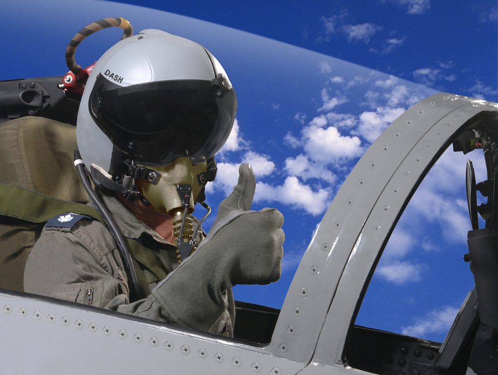
AWS INITIALISATION MODULE BUS EXCHANGE MANAGEMENT MODULE GROUND SUPPLEMENTARY MAINTENANCE MODULES Under each category of functional modules, specific modules were defined and these were termed as terminal functional modules. These terminal functional modules were not decomposed further in the functional architecture. Ada was used as the design language, as well as the coding language except for Bus Exchange Management module, which was implemented in C   Helmet Mounted Display and Sight (HMDS) Integration of DASH-IV Helmet Mounted Display and Sight (HMDS) from M/s Elbit, Israel has been completed and flight tested. Elbit Systems’ Display and Sight Helmet (DASH) enables pilots to aim their weapons simply by looking at the target. DASH measures the pilot’s Line-of-Sight (LOS) relative to the aircraft, and transfers its information to other aircraft systems. Aircraft, sensors, avionics and weapons are thus enslaved to the target. DASH is adaptable to any fighter/attack aircraft and will accommodate advanced missiles and smart weapon lock-on envelopes. DASH is closely integrated with the aircraft's weapon system, via a MIL-STD-1553B bus. An umbilical cable carries power and video drive signals to the internal helmet electronics, and position sensing signals from the helmet to the signal processor box. The umbilical is provided with a quick disconnect connector to provide for safe ejection. The 8.5 kiloVolt high voltage supply for the helmet's Cathode Ray Tube (CRT) is embedded within the helmet, so that no high voltages are present on the umbilical. The tube and supply are embedded in the back of the helmet. The DASH projects the CRT image via a folded optical path directly on to the spherical section visor. This technique was specifically chosen to avoid difficulties with projection optics and the need for additionally tight tolerancing on non-spherical curved visor shapes. The imagery is collimated, so the pilot need not refocus to read the symbology. The DASH provides a solid angle Field of View (FoV) of 20 degrees, with a 15 mm exist pupil for the optics. All symbology is calligraphic, produced by a programmable stroke generator, and a green phosphor is employed. The DASH is tightly integrated with the aircraft's weapon system, tied in via a Mil-Std-1553B multiplex bus. The core of the DASH avionic package is the LCU (Line of sight Computer Unit), which contains the electronics to interpret the output from the position sensing coils in the helmet, the stroke generator electronics to drive the CRT tube, a supervisory processor, and a 1553B bus Remote Terminal interface. The LCU communicates over the bus with the aircraft's Mission Computer. Software running on the Mission Computer interrogates the LCU to get angular measurements in order to cue weapons, and continuously updates the LCU with critical flight information and status information for display to the pilot. The symbology is all programmable in software, and a client Air Force can essentially employ whatever it chooses to. Elbit have not disclosed the number of lines of code in the LCU and Mission Computer interface libraries, although it is know that much of it was programmed in C and Assembly language, not untypical for embedded designs where speed is an issue. 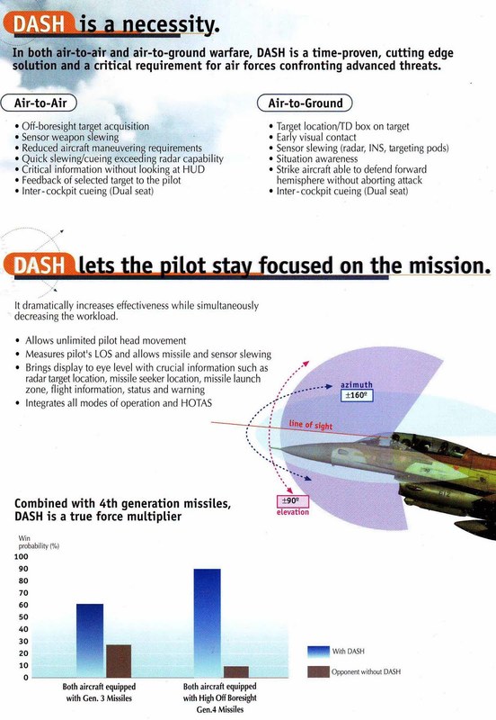 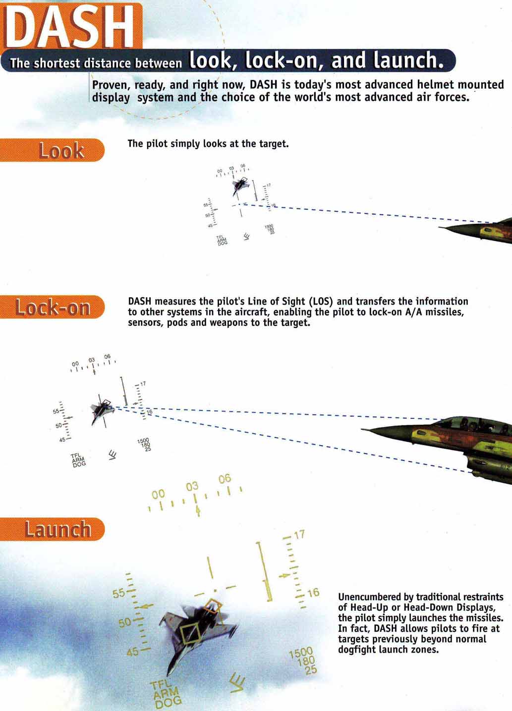 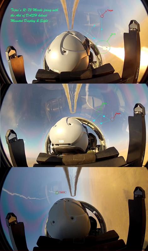
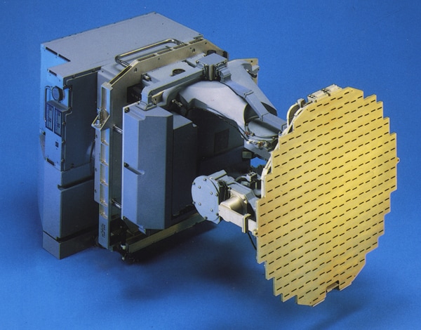
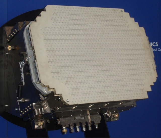
 Sensors 1. Radar Tejas will feature AESA radar. Currently Tejas uses EL/M 2032 radar in MK 1 version. Tejas MK 1A will use EL/M 2052 AESA radar and indigenous UTTAM AESA radar is under development. Due to the small nose cone, AESA in Tejas obviously have a lower range, but it will be well integrated with in the IAF network, and give a quantum technology jump to IAFs combat ability. UTTAM – AESA Uttam AESA is indigenously developed active electronically scanned array (AESA) fire control radar. It is being developed for the LCA Mk2 and Mk1 (presumably Mk1s will be upgraded with the system) and also other aircraft upgrades such as the IAF's Jaguars and MiG-29Ks. Hardware has already been realized for this radar which has a range of 100 km against small fighter sized targets and rooftop testing is underway. Though the Uttam AESA currently weighs 120 kg which is some 40 kg more than the current MMR, there will be no problem in integrating it with the LCA Mk-II which can easily carry radar of this weight. Uttam AESA features LPI and is capable of tracking up to six targets for weapons employment. The salient technical features are: two plane monopulse signals, low side lobe levels and integrated IFF, and GUARD and BITE channels. The heart of MMR is the signal processor, which is built around VLSI-ASICs and i960 processors to meet the functional needs of MMR in different modes of its operation. Its role is to process the radar receiver output, detect and locate targets, create ground map, and provide contour map when selected. Post-detection processor resolves range and Doppler ambiguities and forms plots for subsequent data processor. The special feature of signal processor is its real-time configurability to adapt to requirements depending on selected mode of operation. LRDE lab to keep the Uttam’s interfaces as similar as possible to the current Israeli Elta radar. It is a challenge for LRDE, moving from mechanically scanned radar to the AESA without interface changes but that is the attempt, to save time and forestall any structural changes to the aircraft or sensor. LCA doesn’t have an integrated liquid cooling system necessary for AESA radar; the team has suggested that a small auxiliary compartment that becomes redundant after the mechanical-to-AESA switch could be utilized to house a liquid cooling system. 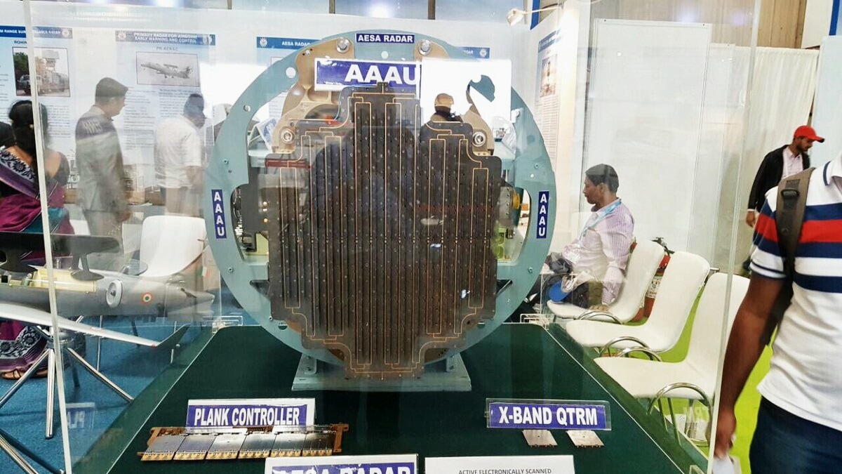 Uttam AESA completed its ground tests and had validated radar performance in Air-to-Air mode. LRDE also completed critical block software tests which opened other modes like high-resolution mapping, multiple grounds moving target detection/tracking and target identification mostly required to perform Air-to-Ground operations. Tejas LSP-2 has been selected to be used has further flying test-bed aircraft for UTTAM. UTTAM has capabilities like, Identification friend or foe (IFF), electronic and communication support measures, C-band line-of-sight and Ku-band SATCOM data-links, etc., similar to those on the AWACS and Conformal Airborne Early Warning & Control Systems (CAEW) systems. The important modes of operation of the UTTAM radar system are the surface surveillance and the air surveillance. The sensor has the abilities to search, track-while-scan, priority tracking, high performance tracking, etc. In priority tracking, the targets will be placed in full track mode even if these cross the primary surveillance area. In high performance tracking, additional measurements are made to improve the tracking accuracy. Utilizing active aperture technology, the radar provides a fast-beam agile system that can operate in several modes concurrently. The radar has state of the art ECCM features including wide band RF front end, ultra low antenna side lobes, frequency and waveform agility, multiple SLC channels for jammer suppression, low probability of intercept, non co-operative target recognition. AESAR provides better situational awareness of the modern battlefield scenario. It is capable of search for 100, tracking up to 6 targets with high accuracy suitable for firing missiles and interleaved Air –to-Air, Air –to-Ground and Air –to Sea modes for all terrain solution. It has ~700 TR modules. Expected Range 150 Km for 2 meter square target. UTTAM is GaAS based. Earlier GaAs TRM procured from US, but they sanctioned it after that, now making GaAs TRMs in India. Cooling requirements is of 3.6KW Features
Environmental Specifications
Preliminary studies have been carried out at Center for Airborne Studies (CABS) for a possible optimal design of a futuristic antenna with the desirable 360°-vision for roles identified under various war situations. The unique aerodynamically-shaped delta radome will blend with the aerodynamics of the platform-aircraft to provide the required radar performance together with better operational economy by virtue of its better aerodynamics, reduced weight, and better or similar electro-magnetics. This radar may be dorsal or conformal fuselage mounted doubts still remain as not much is known about its specifications or configuration. Note: - need more citations/validations about UTTAM. 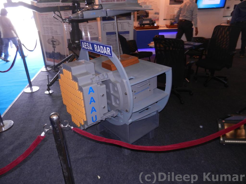 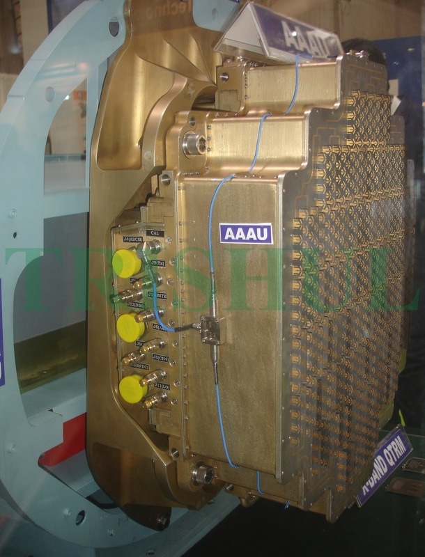 EL/M – 2032 (MK-1) EL/M-2032 is an advanced pulse Doppler, multimode fire control radar intended for multi-mission fighter aircraft. It is suitable for air-to-air and air-to-surface modes. In the air-to-air mode the radar delivers long-range target detection and tracking capability. In the air-to-surface mode, the radar generates high resolution ground imagery using Synthetic Aperture Radar (SAR) technology for smart weapons guidance. Air-to-Sea mode provides long-range detection and tracking as well as target identification capability. EL/M-2032 air-to-air mode has detection and tracking range of up to 150 km, the air-to-ground mode generates high resolution radar imagery of locations at up to 150 km, and air-to-sea mode can detect and classify naval targets at ranges of up to 300 km. The radar system weighs between 72 and 100 kg. Range 100km (5m2 size plane) Features
Operational Modes Air-to-Air
Air Combat Modes (ACM)
Air – to-Ground
Air – To –Sea
 ELM 2052 ( Mk1A) The ELM-2052 is an advanced Fire Control Radar (FCR) designed for air-to-air superiority and strike missions, based on fully solid-state Active Ellectronically Scanning Array (AESA) technology, enabling the radar to achieve long detection ranges, high mission reliability and multi-target tracking capabilities. The ELM-2052 radar provides simultaneous modes of operation supporting multi-mission capabilities for air-to-air, air-to-ground and air-to-sea operation modes, and weapon deployment. This radar utilizes an array of transmit/receive solid-state modules designed to dynamically shape the radiation pattern using ultra-low side-lobe antenna. The radar supports pulse doppler and two axes monopulse guard channel, providing all aspect, look-down shoot-down performance, operating simultaneous multi-mode air-to-air superiority and advanced strike missions. The radar is based on solid-state, active phase array technology enabling the radar to achieve a longer detection range, high mission reliability and a multi-target tracking capability of up to 64 targets. It can also support high resolution target identification and separation, performing raid assessment at long range. as well as surface moving target detection and ranging. In the anti-shipping role the new radar provides long-range target detection, classification and tracking. 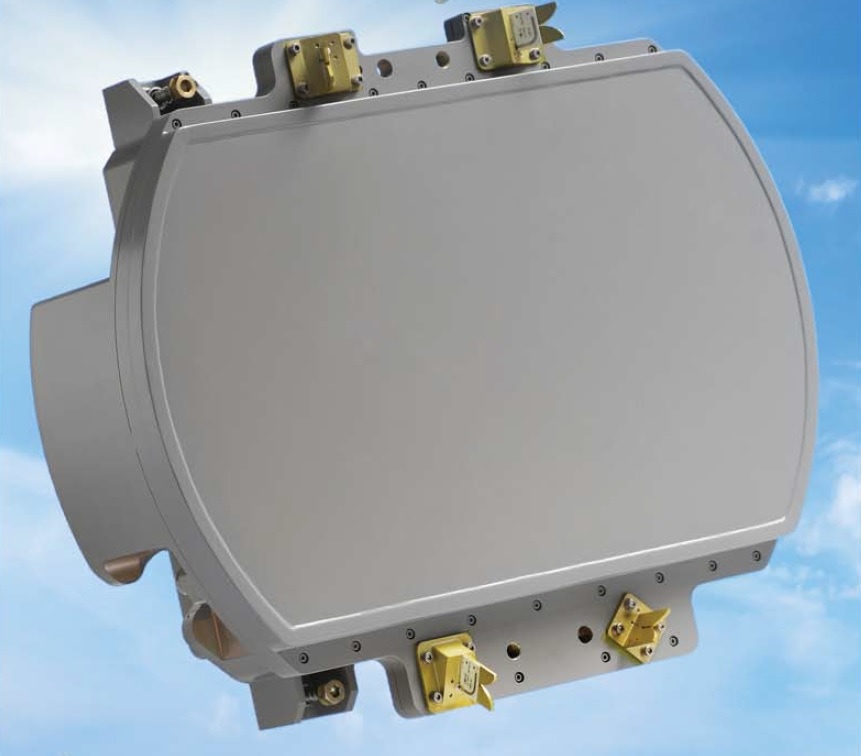 With high peak power the radar support simultaneous multi-mode operation. It can detect targets at very long range while tracking up to 64 targets, and, simultaneously engaging several targets with missiles. In ground attack missions the radar supports mapping, navigation and high resolution imagery (SAR), supported with Real Beam Map (RBM) and Doppler Beam Sharpening (DBS) modes. The EL/M-2052 is designed as a modular system, with built in growth capability, computation and memory reserves. Its weighs about 130 - 180kg and consumes 4 - 10KVA, depending on the design configuration. In the air-to-air mode, the radar delivers very long-range multi target detection and enables several simultaneous weapon deliveries in combat engagements. In air-to-ground missions, the radar provides very high resolution SAR mapping, surface moving target detection and tracking over RBM and SAR maps in addition to A/G ranging. In air-to-sea missions the radar provides long-range target detection and tracking, including target classification capabilities (RS, ISAR). Features
 Operational Modes Air-to-Air
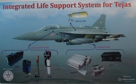
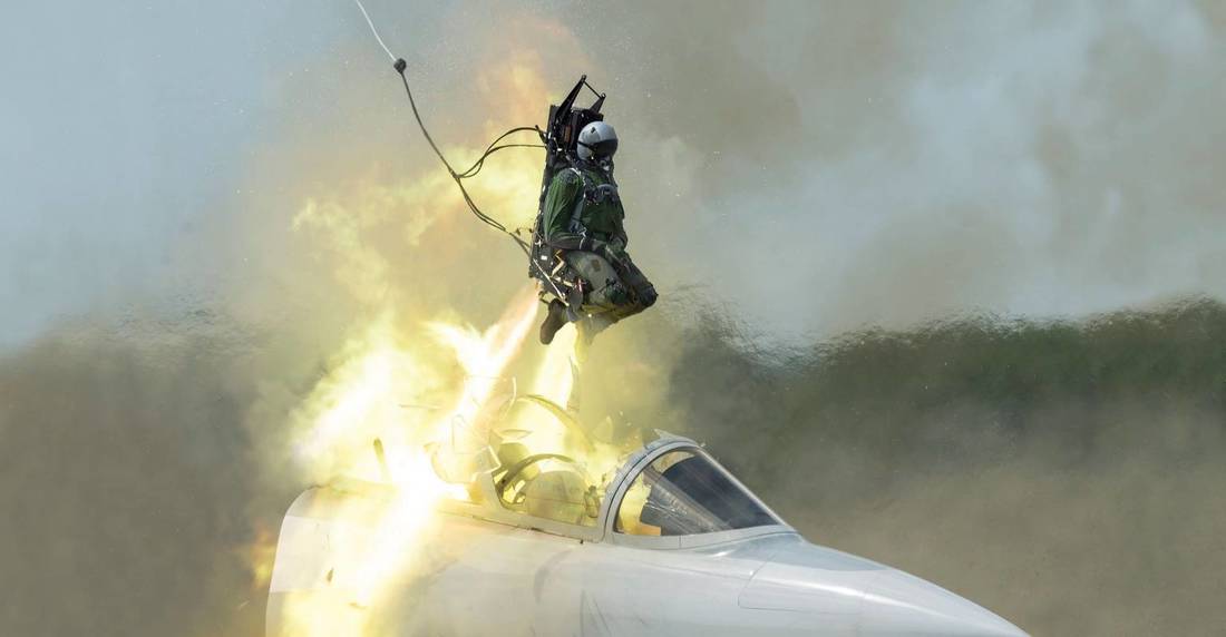
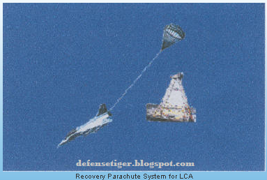
 2. Elta litening pod Litening is a sensor pod which caters to the need of day & night precision strike capability. Low level night flights, laser spot detection and tracking, co-operative target illumination, optical BVR target identification and infrared / secondary navigation. Almost all 4th gen fighters relay on externally mounted pods for some functions. It has a flexible flight envelop includes vertical 9g maneuvers and speed up to mach1.2 at low level and mach 1.8 at 13000 ft. 3. Communication & Navigation Inertial Navigation System Global Positioning System INS GPS: it is the primary navigation sensor and computing unit. INS-GPS performs a wide range of navigation functions such as on-ground autonomous, Interruptible gyrocompass alignment, on-ground fast alignment on stored heading and in-flight alignment on GPS. It computes pure inertial, GPS and optimal navigation by hybridization with embedded GPS receiver. It also performs steering computation. The LCAs secured and jam-proof voice & data communication system operates in the V/UHF band and employs a single LRU based, software driven integrated communication (INCOM). The operating frequency range is 108 to 399.975 MHz, for communication in AM/FM and DATA modes over 9240 channels. It features frequency hoping. Direct Sequence Spread Spectrum technology and secrecy among other ECCM features. The COM 1150A standby UHF unit used for air to air and air to ground voice telephony conversation, is a 7000 channel UHF transceivers with an operating frequency range between 229 & 399.975 Mhz. To meet the highly stringent navigation accuracies required, the LCAs hybrid navigation system is centered on an inertial navigation system with a ring-laser-gyro combined with GPS/GLONASS receiver. The Ring Laser Gyro developed by RCI based on Total Internal Reflecting Prism (TRP) technology and features a unique square laser cavity of 28 cms cavity length. Specifications include Scale Factor Stability of 0.01 degree/H and random walk of 0.003degree/H. the integration of GPS greatly enhances reliability, robustness as well as the complete dependency on standalone system. 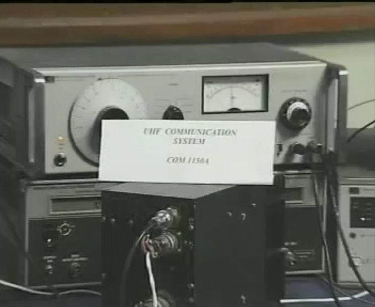 Components of Navigation system Tactical Air Navigation TACAN: it is a line-of-sight system and provides slant range of the aircraft from the ground station using transmitter / responder technique. RAM-1701A Radio Altimeter (RADALT):- This modular, solid state systems act as the height finder for the aircraft over terrain, between 0 and 1500 m altitude. As with all major LRUs, the RADALT is provided a MIL-STD-1553 interface. It gives altitude of the aircraft above the terrain just below the aircraft, and the height information for low level flights for weapon aiming computations on the display surfaces. VHF Omni Range–Instrument Landing System (VOR-ILS): Smart Standby Displays SSDUs: Two smart standby displays provide independent display information of critical parameters to pilot to serve as backup to primary displays Get-U-Home. Onboard Recording System: Two onboard recording systems viz., digital video recorder for all the data buses and video information and solid-state crash data recorder SSCDR for all critical parameters on ground these are supported by data analysis systems 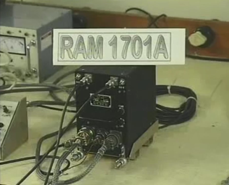 ~Data-link The LCA is provided with separate secure multi directional data link, capable of data rate of 8Kb/s (Min). Fitted along with INCOM unit, it enables real time reception and transmission of tactical and sensor information to/from the Ground station, AWACS and/or other aircraft or buddy – buddy information groups of other LCA. Providing real time multiplexed voice and data on the threat environment or scenario. It considerably reduces dependency on onboard sensors and ensures maximum situational awareness with the fusion data from various platforms. It also enhances the co ordination o strike group. ~IFF Identification Freind or Foe The IFF system developed by CABS, basically consists of interrogator and transponder subsystems for air – air (IFF-AA) and air to ground (IFF-AG) interrogation. Targets / aircrafts fitted with a compatible transponder (IFF 1410A) receives the coded signal sent by the interrogator and replies in the specified direction with another coded signal. These are received by the interrogator, processed and sent to the radar data processor on the MIL-STD-1553 Bus and the display units. 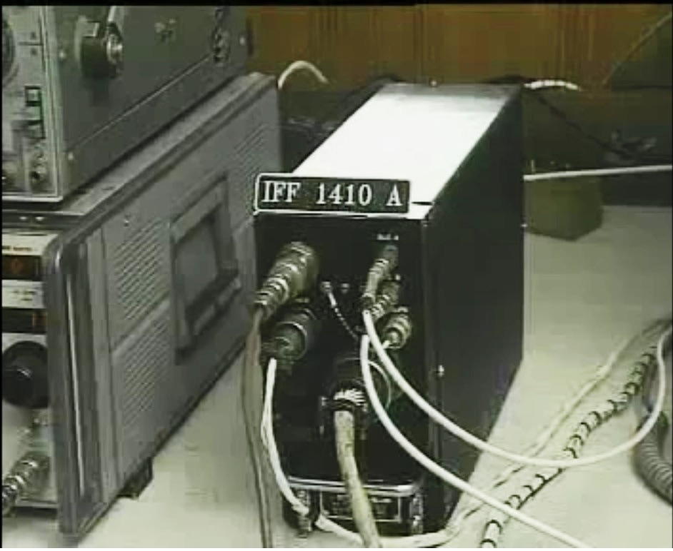 Electronic Warfare.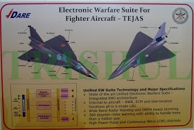 The Tejas Mark I was to have an "on-board EW system", but lack the space for one. It has, therefore, been decided to develop an EW pod for the Mark 1A, which will be carried externally under the fighter's wing. ~Mayavi EW Suite MAYAVI EW (Electronic Warfare) Suite developed by India for her fighter jets especially Tejas. Few components from this suite like Tarang 2 radar warning receiver (RWR) is used in Su 30 MKI too. This warfare suite adds an important capability to our LCA. LCA is the first fighter aircraft of India fitted with radar warner and jammer equipment with capability for both radar warning and jamming using a unified EW technology. The electronic warfare suite is designed to enhance combat survivability during deep penetration. The EW suite is developed by the Defense Avionics Research Establishment (DARE) with support from the Defense Electronics Research Laboratory (DLRL). This EW suite includes a radar warning receiver (RWR), Missile Approach Warning (MAW), Laser warning receiver (LWR) system, Infrared & Ultraviolet Missile warning sensors, self-protection jammer, chaff, jaff and flares dispenser, an electronic countermeasures (ECM) suite and a towed radar decoy (TRD). However we have no confirmation that the Mayavi is an external system. The advantage of an EW Suite is, it possesses a self-protection jammer to alert the pilot against incoming threats. The suite is built around state-of-the-art Unified Electronic Warfare System (UEWS)—an internal EW system consisting of a Unified Receiver Exciter Processor (UREP) with advanced digital receiver/Digital Radio Frequency Memory (DRFM) concepts are integrated with Microwave Power Module (MPM)-based transmitter for LCA 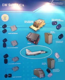 ~Air Data Computer (ADC) ADC developed by ADE is an extremely compact real-time embedded computer based on Intel 80960MC 32 bit-processor. The architecture is optimized for quad redundant application with redundancy management software to perform real failure detection and control reconfiguration. ADC houses four pressure transducers with pneumatic connections at the front panel. The variable frequency output of the pressure transducer is converted through hardware implemented Frequency to Digital converters assuring accuracy of 0.02% of full scale value. Temperature compensation is provided with a divide output for each transducer. It also provides analog and discrete interfaces to sense Total Air Temperature through 3-wire RTD sensor, Angle of Attack through RVDT sensors and De-icing Currents through current transformers. ADC is equipped with high speed serial link for ground support applications like ‘real time debugging’ and ‘program download’ essential for pre & post flight checks. It can communicate with other three similar ADCs for quad redundant application through dedicated inter ADC communication link. It can communicate with host Digital Flight Control Computer (DFCC) through a dedicated RS 422 serial link. ADC has XILINX vertex series FPGA for logic hosting using soft IP codes along with special purpose ASICs for efficient signal conditioning and Built –In-Test coverage. It is designed to meet stringent environmental and lightning requirements of flight critical LRUs. ~Salient Features Compact, conduction cooled chassis with front panel filter pin assembly. Integrated motherboard & fex assembly Logic implementation on Re-programmable XILINIX FPGA using soft IP codes Inter ADC Communication Controller for redundancy management of distributed ADCs Built –In-Test test features like wrap around for transmitter and receivers, UART loop back and echo modes Facilities for software downloading and real time debugging 5 no’s, of high speed input data links and corresponding output data links NVM Auto store/Power on Recovery for Fault logging /retrieval 4-channel phase sensitive de-modulators for position sensing for AOA/similar sensors High performance Power supply module to generate required internal voltages from 28 VDC Excitation & signal conditioners of 3-wire RTD for measurement of total Air temperature 3-channel RMS-DC converter for heater current monitoring 15 no’s of open / gnd Discrete inputs and 5 no’s of open/ gnd Discrete outputs for communication with GSE, Cockpit & other LRUs Internal power voltage monitors Weight < 3kg & Volume 155x133x120mm MTBF > 10,000Hrs BIT converge > 95% Designed to meet MIL-STD-704D, MIL-STD-810E, MIL-STD-461C, SAE-AE4L-87-3A environmental /EMI/EMC/lightning specification Materials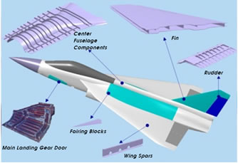 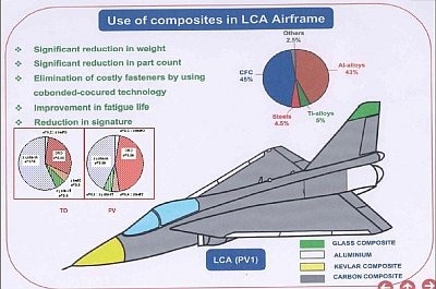 The Tejas employs CFC materials for up to 45% of its airframe, including in the fuselage (doors and skins), wings (skin, spars and ribs), elevons, tailfin, rudder, air brakes and landing gear doors. Composites are used to make an aircraft both lighter and stronger at the same time compared to an all-metal design, and the LCA's percentage employment of CFCs is one of the highest among contemporary aircraft of its class. Apart from making the plane much lighter, there are also fewer joints or rivets, which increases the aircraft's reliability and lowers its susceptibility to structural fatigue cracks. The use of composites in Tejas results a 40 percent reduction in the total number of parts. For instance 3000 parts in a metallic design would come down to 1800 parts in composite design. The no of fasteners has been reduced to half in composite structure from 10,000 in metallic frame. The composite design helped to avoid about 2000 holes being drilled into the airframe. Though the weight comes down by 21 percent, the most interesting thing is the time take to assemble LCA – the airframe that takes eleven month come down to 7 month using composites. While each of these factors can reduce production costs, an additional benefit. CFC have other advantages they don’t deteriorate with age nor corrode due weather elements, CFC also gives Tejas better operational empty weight giving Tejas better thrust to weight ratio when compared with other aircrafts with similar engines. CFC does have their own disadvantages, there are expensive to make. Another major advantage of Tejas is it is very easy to maintain. Unlike MiGs, Jaguars and Mirages which have more than 12,000 components, the Tejas has about 6,000; the lesser the components the easier the maintenance. It took three days for a MiG-21 engine to be taken out of the aircraft. The Tejas engine comes off in less than 15 minutes. 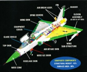 Major Components Composite Fin: - The entire box is made as a single piece in one operation using Innovative and complex tooling concepts. Composite Rudder: - Integral rib-skin co-cured construction has resulted in 20% weight reduction, eliminated expensive and complex machining of titanium torque shaft and resulted in weight savings of 35 %. Co-cured co-bonded wing: - LCA wing components have been manufactured separately and joined together using rivets, fastener and sealant. In the proposed co-cured co-bonded wing, the bottom skin, ribs and spars are cured together. This has advantage from reduced part count as well as weight saving. The weight saving is mainly due to the elimination of sealants, fasteners and associated components. Further, the wing is expected to have improved stiffness, leak proof and better lightning protection. The wings of Tejas have been designed to provide a minimum weight structure & to provide minimum weight structure and to serve as integral fuel tank. Materials like CFC & AL – Li alloy have been used for the wing construction of tejas. As the wings carry fuel also, the lightening protection for wings has been evolved through detailed studies and experimentation. The wings are easy to maintain. 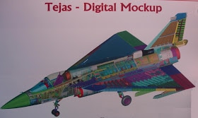 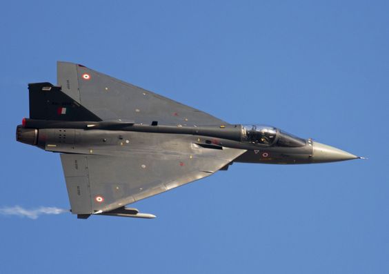 Salient Features Top & bottom interspar skins & intermediate spars made of CFC Main wing fuselage attachment brackets made of conventional and well proven A/ alloy Heavily loaded components like pylon support brackets, slat track ribs made of Ti/Al alloy Other machined & sheet metal components made from Al-Cu/Al-Li alloys Most of the fatseners are Ti screws and stainless steel nuts/anchor nuts Highly optimized wing, with appropriate variation of thickness, camber and twist along the span. Cross sectional area distribution along the length, adjusted for good high speed characteristics Leading edge slats, scheduled at higher AoA , for favorable aerodynamic behavior Wing shielded bifurcated air intake duct, with diverters, suitably matched with engine to avoid buzz & to minimize distortion throughout the flight envelop Safety Features employed in TejasTejas incorporates many world class systems to ensure the safety of pilots. Major systems are..........
|
AuthorPalash Choudhari Archives
June 2021
Categories
All
|
 RSS Feed
