 Stealth is the corner stone of 5th gen air fighters. Stealth tech also called Low Observable (lo) tech is a collection of techniques that makes objects less visible to radar, infrared, sonar and other detection methods. Stealth d doesn't mean it is invisible stealth is used to delay the detection as far as possible. Stealth is applicable to aircraft's ships, submarines, missiles, satellites & even personals too. Here we only talk about stealth aircraft's. Before continuing we are like to give a small description about how a radar works makes further reading easier. The basic idea is the radar antenna to send out a burst of radio energy, which is then reflected back by any object it happens to encounter. The radar antenna measures the time it takes for the reflection to arrive, and with that information can tell how far away the object is.The metal body of an airplane is very good at reflecting radar signals, and this makes it easy to find and track airplanes with radar equipment. One of the main focuses while developing a 5th gen fighter is reducing the Radar Cross Section (RCS) thus improving the stealth capabilities of the fighter. RCS is a measure of how detectable an object is with radar. A larger RCS indicates that an object is more easily detected The 4 basic methods of reducing RCS are
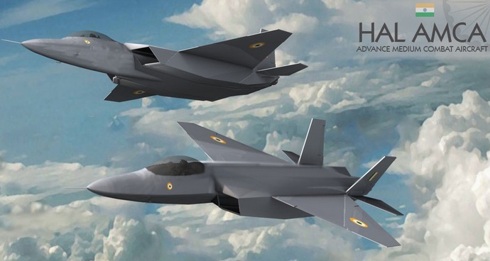
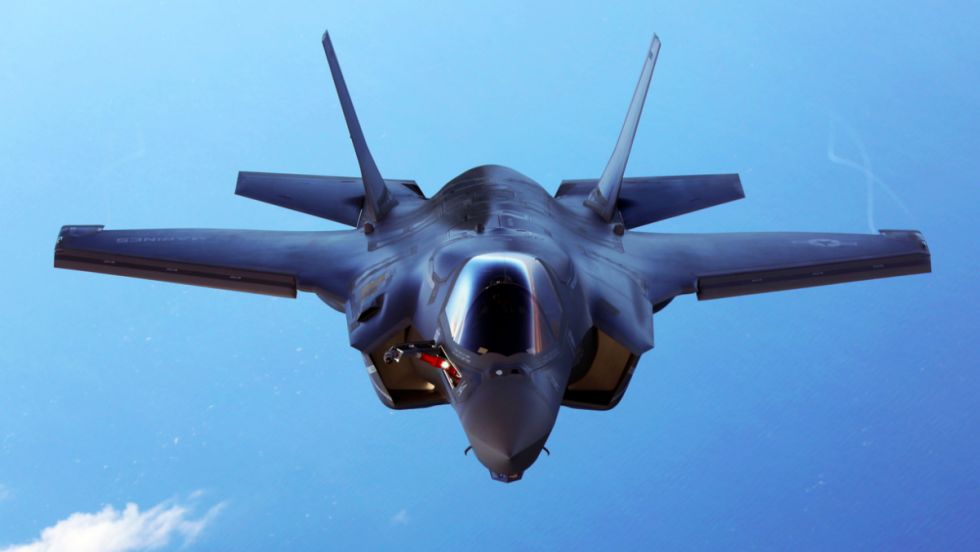
Shaping The most important factor affecting the RCS is the geometry of or the shape of the target. In order to reduce the RCS the surfaces edges should be oriented in such a way so as to reflect the radar energy away from the expected radar antenna & not back to it. This design principle commonly called “Plan Form Alignment”. The designers tried to avoid any possible surface or edge whose normal vectors would look at a direction where possible enemy radar might be found, especially for the frontal aspect. Therefore, in the frame of RCS reduction all bumps curves etc should be avoided in the same way any external load (pylons, bombs, missiles, fuel tanks etc) would considerably augment the total RCS. This is the reason why low observable (LO) aircraft carry the armament internally, in special bays. Furthermore, armament bays & landing gear bay doors should close tightly with no gaps in between, generally any irregularity in of the surface could incur an RCS increase. The engine blades should be carefully hidden inside the intake duct. The whole air intake construction is critical when designing a LO aircraft.  FACTORS THAT AFFECT RCS Size: As a rule the larger an object, the stronger its radar reflection & thus greater RCS Material: Materials such as metal are strongly radar reflective & tend to produce strong signals. 5th gen fighters are commonly using carbon composites, titanium alloys, thermoset composites ...etc Shape: if the radar waves be incident at a large angle (normal ray) that will then bounce off at a similarly high reflected angle; it is forward scattered. The edges are sharp to prevent there being rounded surfaces. Rounded surfaces will often have some portion of the surface normal to the radar source. As any ray incident along the normal will reflect back along the normal this will make for a strong reflected signal. From the side, a fighter plane will present a much larger area than the same plane when viewed from the front. All other factors being equal, the plane will have a stronger signal from the side than from the front so the orientation between the radar station & the target is important The incident angle: angle at which the radar beam hits a particular portion of target which depends upon shape of the target & its orientation to the radar source) Polarization: The polarization of transmitted & the received radiation in respect to the orientation of the target 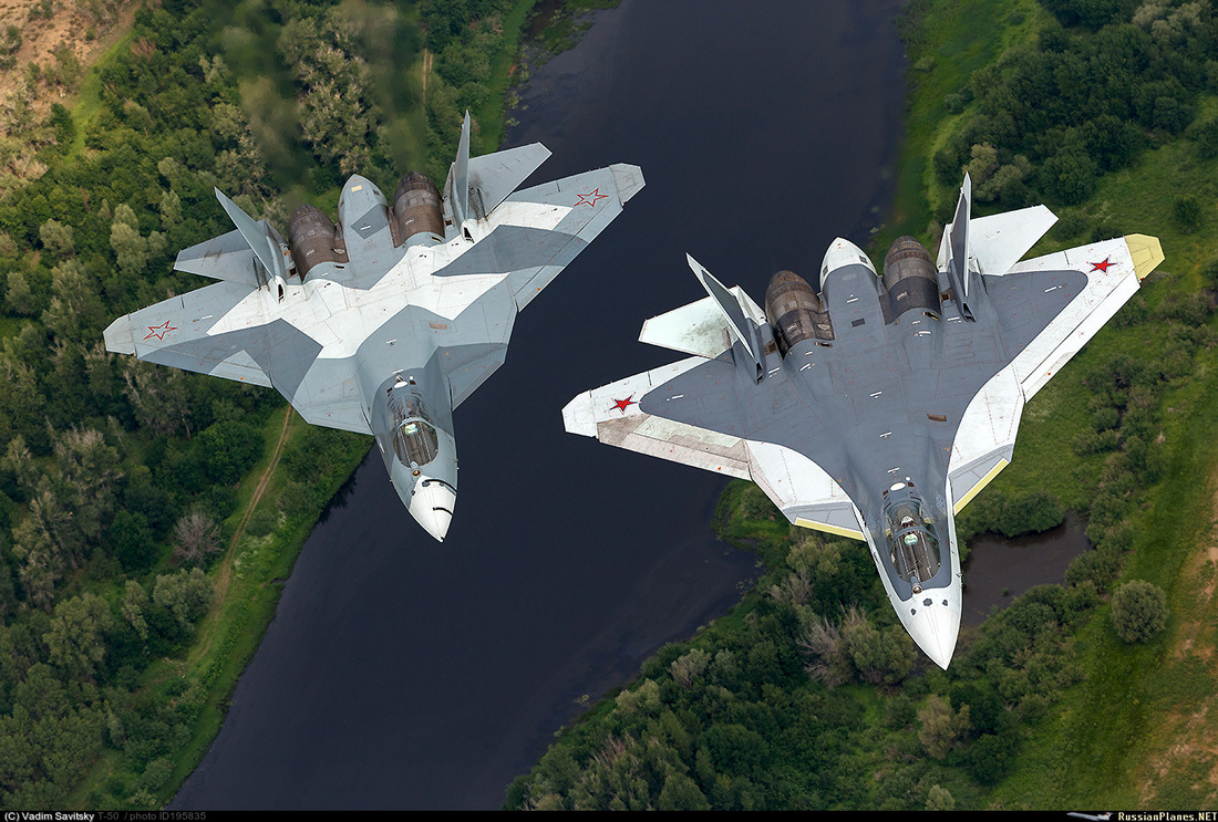 Some Common Design Features in LO Aircrafts
 Radar Absorbing Materials The special shaping is the most important lo method & it is responsible for the main part of RCS reduction. The second technique is the use of special radar absorbent material (RAM) which absorbs (part of) the received radar energy & convert it to heat reducing in this way the reflected energy. Materials absorbency at a given frequency of radar wave depends upon its composition. RAM cannot perfectly absorb radar at any frequency, but it does have greater absorbency at some frequencies rather than others. There is no RAM suited to absorption of all radar frequencies. A radar absorbent material can significantly reduce objects RCS in specific radar frequencies, but it does not result in “invisibility” on any frequencies. There are mainly 2 kinds of RAM’s Resonant and Non-Resonant RAM’s. Usually non-resonant RAM is used to coat the reflective surface. They will absorb incident radar waves and convert a large percentage of them into heat. A major advantage of non-resonant RAM is that it can be effective over a wide range of frequencies Resonant RAM is seldom used because, in contrast to non-resonant RAM, this type of RAM is only useful against radar with a single, common, and unchanging frequency. Bad weather may contribute to deficiencies in stealth capability. It is considered as a supplementary approach. In any case the application of RAM is also a trade off, since any special painting or coating adds to the cost. RAM may require special treatment & maintenance 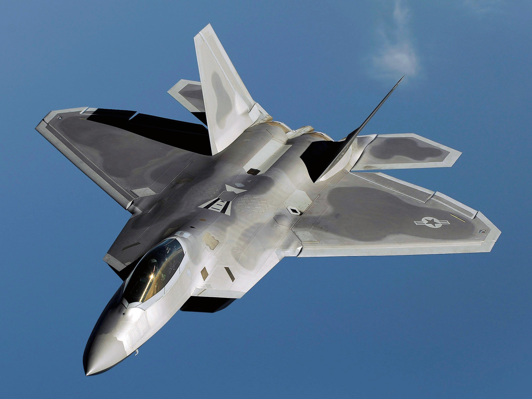 Passive Cancellation Sometimes also mentioned as “Impedance Loading”, passive cancellation is based on the idea of creating a (passive) echo source, whose amplitude & phase would be adjusted to cancel another echo source (E.g. by drilling a cavity or port of specific dimensions and shape on the object body). This approach attracted some interest in the past but now seems not so promising any more. Active Cancellation Also called Active Loading is based on the same principle as passive cancellation which is the creation of an appropriate “destructive echo” which would cancel the real echo of the target to the radar. Therefore that angle should emit electromagnetic energy synchronized with the received radar energy with proper amplitude & phase in order to minimize the reflected signal. In other words the target should take into account the direction of arrival of the radar energy, the amplitude, the frequency, the phase its own RCS characteristics for the specific frequency & direction and should be adequately intelligent to create the proper wave form, emitting the right pulse at the right direction at the right time. The technical difficulties are obvious, as well as the possibility to convert the target into a “beacon” of radar energy in case wrong implementation. This technique has been reported to be applied by the Rafale and has been implicitly confirmed by Dassault. This technique is integrated in the SPECTRA electronic warfare system of Rafale. Using active cancellation the RCS of Rafale reduced to 0.06M2 one of the best figures in all the 4.5 gen fighters. Another attempt in the category of Active Stealth is the so called “Plasma Stealth” tech. there have been reports that Russia were conducting experiments on this idea and Russia’s 5th gen T 50 & Su 35 incorporates some degree of Plasma Stealth. This tech employs ionized gas(Plasma), which produced by special device on board & injected in front of the aircraft, creating a protective cloud reducing considerably the aircraft RCS. 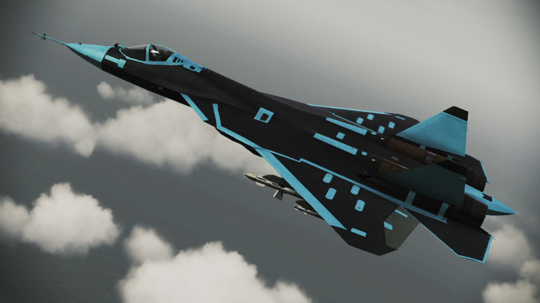 image credits :- Sourav Choradia, f16.net, tonnel-ufo.ru Info Credits :- NASA official website.
Franklin Medina Toledo
6/8/2019 10:29:09 pm
I like know about the avionic Leave a Reply. |
AuthorPalash Choudhari Archives
June 2021
Categories
All
|
 RSS Feed
