|
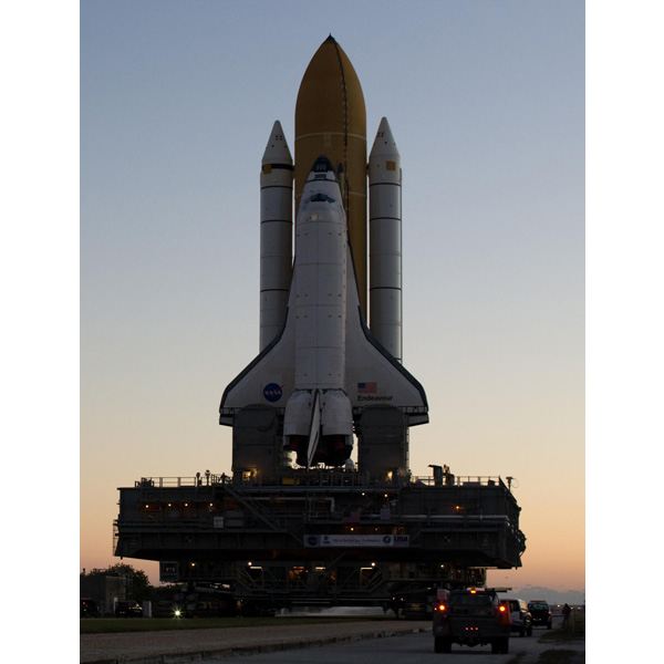
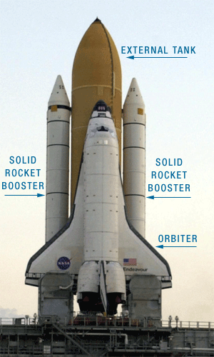
The Space Shuttle was a partially reusable low Earth orbital spacecraft system operated by NASA, as part of the Space Shuttle program. In this article, we examine the monumental technology behind America's shuttle program, the mission it was designed to carry out. First, let's look at the parts of the space shuttle and a typical mission. The space shuttle consists of the following major components:
A typical shuttle mission is as follows:
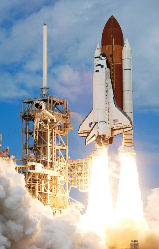
To lift the 4.5 million pound (2.05 million kg) shuttle from the pad to orbit (115 to 400 miles/185 to 643 km) above the Earth, the shuttle uses the following components:
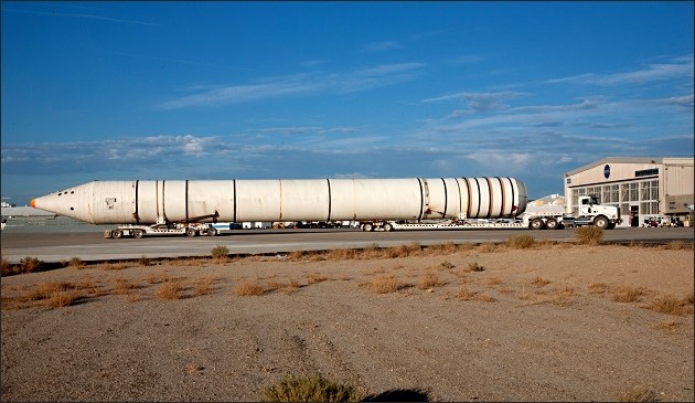
Solid Rocket Boosters The SRBs are solid rockets that provide most of the main force or thrust (71 percent) needed to lift the space shuttle off the launch pad. In addition, the SRBs support the entire weight of the space shuttle orbiter and fuel tank on the launch pad. The SRBs were jettisoned two minutes after launch at a height of about 46 km (150,000 ft), and then deployed parachutes and landed in the ocean to be recovered. The SRB cases were made of steel about ½ inches (13 mm) thick. The solid rocket boosters were re-used many times. Over 5,000 parts were refurbished for reuse after each flight. On the pad, the two SRBs carried the entire weight of the external tank and orbiter and transmitted the weight load through their structure to the mobile launch platform. Each booster had a liftoff thrust of approximately 2,800,000 pounds-forces (12 MN) at sea level, increasing shortly after liftoff to about 3,100,000 lbf (14 MN). While the terms "solid rocket motor" and "solid rocket booster" are often used interchangeably, in technical use they have specific meanings. The term "solid rocket motor" applied to the propellant, case, igniter and nozzle. "Solid rocket booster" applied to the entire rocket assembly, which included the rocket motor as well as the recovery parachutes, electronic instrumentation, separation rockets, range safety destruct system, and thrust vector control. The boosters were composed of seven individually manufactured steel segments. Astronauts who have flown on multiple spacecraft report that Shuttle delivers a rougher ride than Apollo or Soyuz. The additional vibration is caused by the solid rocket boosters, as solid fuel does not burn as evenly as liquid fuel. The vibration dampens down after the solid rocket boosters have been jettisoned The solid rocket motor ignition commands were issued by the orbiter's computers through the master events controllers. Each SRB had two hydraulic gimbal servo actuators, to move the nozzle up/down and side-to-side. This provided thrust vectoring to help control the vehicle in all three axes (roll, pitch, and yaw). The ascent thrust vector control portion of the flight control system directed the thrust of the three shuttle main engines and the two SRB nozzles to control shuttle attitude and trajectory during lift-off and ascent. Commands from the guidance system were transmitted to the ATVC (Ascent Thrust Vector Control) drivers, which transmitted signals proportional to the commands to each servoactuator of the main engines and SRBs. Four independent flight control system channels and four ATVC channels controlled six main engine and four SRB ATVC drivers, with each driver controlling one hydraulic port on each main and SRB servoactuator. Each SRB servoactuator consisted of four independent, two-stage servovalves that received signals from the drivers. Each servovalve controlled one power spool in each actuator, which positioned an actuator ram and the nozzle to control the direction of thrust. The Solid Rocket Booster separation sequence began when the three pressure sensors in each booster detected a chamber pressure of 50 psi or less. In case of a sensor failure, the time from liftoff was used to determine the point of SRB separation. Right before the time of booster separation, the nozzles in the motor are put into a null position and the Orbiter Vehicle goes into the second stage of flight. Once the sensors send the command, small detonators ignite separating the SRBs from the external tank within 30 milliseconds of the firing command. At the same time, four booster separation motors that are located at the aft end of each booster ignite and move the SRBs away from the shuttle. These motors provide thrust for about one second. Seventy-five seconds after separation, SRB apogee occurred at an altitude of approximately 220,000 ft (42 miles). Parachutes were then deployed and the SRBs floated back down to Earth. Impact occurred in the Atlantic Ocean approximately 122 nautical miles downrange from the launchpad. Specially fitted NASA recovery ships, the MV Freedom Star and the MV Liberty Star would then be dispatched to retrieve the SRB’s to bring them back where they would be refurbished for the next mission. Each SRB has the following parts:
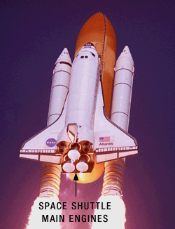
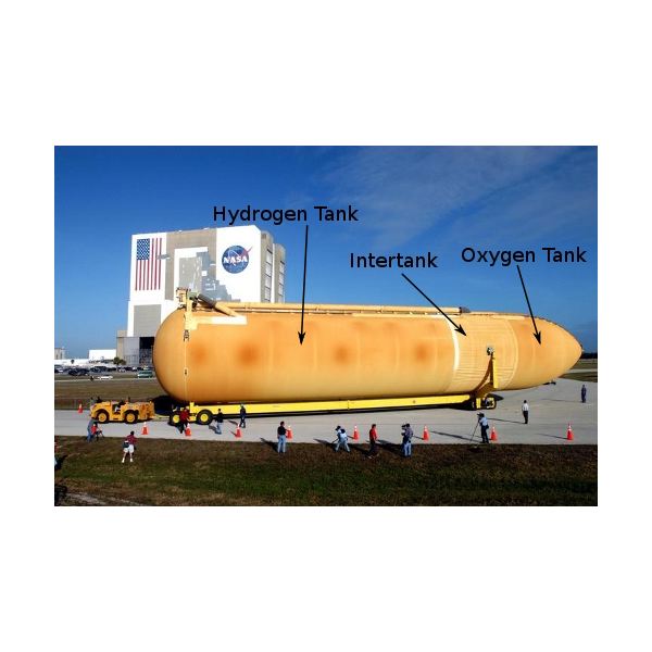
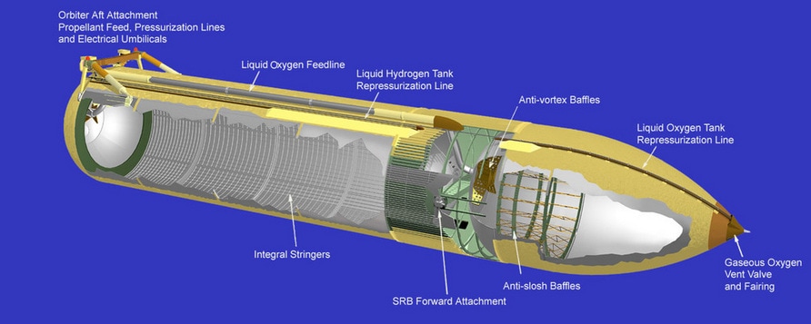
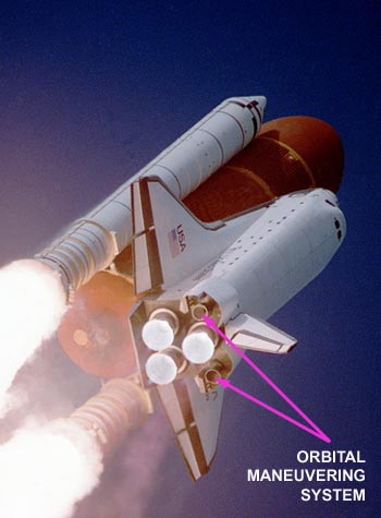
Main Engines The Aerojet Rocketdyne RS-25, otherwise known as the Space Shuttle main engine (SSME), is a liquid-fuel cryogenic rocket engine that was used on NASA's Space Shuttle and is planned to be used on its successor, the Space Launch System. On the Space Shuttle, the RS-25 was mounted in the aft structure of the orbiter . The orbiter has three main engines located in the aft (back) fuselage (body of the spacecraft). Each engine is 14 feet (4.3 m) long, 7.5 feet (2. 3 m) in diameter at its widest point (the nozzle) and weighs about 6,700 lb (3039 kg). The main engines provide the remainder of the thrust (29 percent) to lift the shuttle off the pad and into orbit. Following each flight, the engines were removed from the orbiter, inspected and refurbished before being reused on another mission. The engines burn liquid hydrogen and liquid oxygen, which are stored in the external fuel tank (ET), at a ratio of 6:1. They draw liquid hydrogen and oxygen from the ET at an amazing rate, equivalent to emptying a family swimming pool every 10 seconds! The fuel is partially burned in a pre-chamber to produce high pressure, hot gases that drive the turbo-pumps (fuel pumps). The fuel is then fully burned in the main combustion chamber and the exhaust gases (water vapor) leave the nozzle at approximately 6,000 mph (10,000 km/h). Each engine can generate between 375,000 and 470,000 lb (1,668,083 to 2,090,664 N) of thrust; the rate of thrust can be controlled from 65 percent to 109 percent maximum thrust. The engines are mounted on gimbals (round bearings) that control the direction of the exhaust, which controls the forward direction of the rocket The engine produces a specific impulse of 452 seconds (4.43 km/s) in a vacuum, or 366 seconds (3.59 km/s) at sea level, has a mass of approximately 3.5 tons (7,700 pounds), and is capable of throttling between 67% and 109% of its rated power level in one-percent increments. The RS-25 operates at temperatures ranging from −253 °C to 3300 °C. The SSME had a lifetime rating of 27,000 seconds, equivalent to 55 missions. The operating conditions that set it apart from other contemporary high-performance engines were the extremely high system pressures. A high combustion-chamber pressure (greater than 3,000 psi) permitted a higher expansion ratio and higher rated vacuum thrust, 470,000 pounds, from a compact combustion chamber. External Fuel Tank External Tank (ET) was the component of the Space Shuttle launch vehicle that contained the liquid hydrogen fuel and liquid oxygen oxidizer. During lift-off and ascent it supplied the fuel and oxidizer under pressure to the three Space Shuttle Main Engines (SSME) in the orbiter. The ET is made of aluminum and aluminum composite materials. It has two separate tanks inside, the forward tank for oxygen and the aft tank for hydrogen, separated by an intertank region. Each tank has baffles to dampen the motion of fluid inside. Fluid flows from each tank through a 17-inch (43 cm) diameter feed line out of the ET through an umbilical line into the shuttle's main engines. Through these lines, oxygen can flow at a maximum rate of 17,600 gallons/min (66,600 l/min) and hydrogen can flow at a maximum rate of 47,400 gallons/min (179,000 l/min). The ET is covered with a 1-inch (2.5 cm) thick layer of spray-on, polyisocyanurate foam insulation. The insulation keeps the fuels cold, protects the fuel from heat that builds up on the ET skin in flight, and minimizes ice formation. When Columbia launched in 2003, pieces of the insulating foam broke off the ET and damaged the left wing of the orbiter, which ultimately caused Columbia to break up upon re-entry. Unlike the Solid Rocket Boosters, external tanks were not re-used. The Tank is the biggest and heaviest part of the Shuttle Stack. It is basically divided into three parts, the liquid Hydrogen Tank, the Intertank and the liquid Oxygen Tank. The SRBs are directly attached to the ET. The lower portion of the ET is the lquid Hydrogen Tank. It consists of four cylindrical barrel sections, an aft dome and a forward dome. Five Ring Frames provide stability and attach the LH2 Tank to the Intertank. They also provide stability and cushion Orbiter and SRB loads. The forward and aft domes are identical in shape. The forward dome includes outfitting for the LH2 vent valve and the LH2 pressurisation line. A vent line is needed because of the special characteristics that cryogenic fuel has. When tanking is complete, the Liquid Hydrogen Tank enters 'stable replenish'. That means that Hydrogen boils off, because the temperature inside the tank is still higher than the boiling point of Hydrogen. That gaseous Hydrogen is being removed through this vent line and is burned off at the Flame Stack. The Hydrogen that is lost has to be put back in liquid form. The Hydrogen Vont Line connects to the ET through the Ground Umbilical Carrier Plate. The GUCP separates from the ET at the time of SRB ignition. The Aft Dome houses the LH2 connectors to the Feedline. The outlet is 17 inches in diameter. The Intertank joins the LH2 portion and the LOX portion of the tank. Basically it's a gap that is filled with various equipment. It is also a key component in terms of stability, because it takes a lot of thrust loads from the Solid Rocket Boosters which are connected to the Intertank structure. It also balances loads between the LH2 and the LOX Tank. The Intertank facilitates instrumentation and provides an umbilical plate that interfaces with the ground facility arm for purge gas supply, hazardous gas detection and hydrogen gas boiloff. The upper portion of the ET is the liquid Oxygen Tank which is smaller in size than the LH2 Tank. It has an ogive shape due to aerodynamical reasons (drag reduction). This tank also feeds in a line of 17 inches diameter that is located on the outside of the ET and extends to the interface point where the umbilicals are connected to the Orbiter. It also has a venting assembly that allows gaseous Oxygen to leave the tank. That interfaces with the Oxygen Vent Hood that is located on top of the ET and is retracted roughly 3 minutes before Liftoff. The Thermal Protection System of the External Tank is composed of isolation foam and pre-shaped parts of insulation. Thermal conditioning is needed for various reasons. A phenolic thermal insulator prevents air from liquifying on exposed metal surfaces that are extremely cold due to the cryogenic fuels inside the tank. Also, it prevents heat from flowing into the Hydrogen which reduces the amount of Hydrogen that boils of during stable replenish. The foam also ensures that no ice forms on the outside of the ET. Pieces of ice breaking off during flight could damage the Orbiter, especially the Thermal Tiles that are exposed to the ET. The ET TPS has its known flaws. The problem of pieces of foam liberating during powered flight has not been solved by NASA. From the beginning of the program, foam liberations were observed, but not taken seriously. Shortly after the launch of STS-107, a piece of foam impacted the left wing of Space Shuttle Columbia and left a basketball-sized hole in the reinforced carbon-carbon. During re-entry, super heated gases were able flow inside the Orbiter's strucure causing it to desintegrate. Columbia and her crew were lost. Following the disaster, new safety mechanisms were added, however these are just monitoring foam events and scan the Orbiter for possible damage. There are four propellant depletion senors installed on each of the tanks. The ones that monitor Hydrogen depletion are at the bottom of the LH2 Tank. The Oxygen sensores are mounted inside the LOX Feedline allowing the maximum amount of Oxygen to be consumed by the engines. Main Engine Cutoff is based on a pre-determined velocity, but the signal from the sensors have priority. Should the sensors show a dry condition of either oxidizer or fuel, the engines will be commanded to shut down. Several pressure sensors are mounted in the upper portion of the tanks. The ET has also cameras installed on it. The LOX Feedline camera has its own power supply and transmitter so that it can provide downlink television after ET separation. Orbital maneuvering system and liftoff. The Space Shuttle Orbital Maneuvering System (OMS) is a system of hypergolic liquid-propellant rocket engines used on the Space Shuttle. Designed and manufactured in the United States by Aerojet, the system was used during launch to produce supplementary thrust and on-orbit to provide orbital injection, orbital correction and the spacecraft's deorbit burn. The two orbital maneuvering systems' (OMS) engines are located in pods on the aft section of the orbiter, one on either side of the tail. These engines place the shuttle into final orbit, change the shuttle's position from one orbit to another, and slow the shuttle down for re-entry. The OMS engines burn monomethyl hydrazine fuel (CH3NHNH2) and nitrogen tetroxide oxidizer (N2O4). Interestingly, when these two substances come in contact, they ignite and burn automatically (i.e., no spark required) in the absence of oxygen. The fuel and oxidizer are kept in separate tanks, each pressurized by helium. The helium pushes the fluids through the fuel lines (i.e., no mechanical pump required). In each fuel line, there are two spring-loaded solenoid valves that close the lines. Pressurized nitrogen gas, from a small tank located near the engine, opens the valves and allows the fuel and oxidizer to flow into the combustion chamber of the engine. When the engines shut off, the nitrogen goes from the valves into the fuel lines momentarily to flush the lines of any remaining fuel and oxidizer; this purge of the line prevents any unwanted explosions. During a single flight, there is enough nitrogen to open the valves and purge the lines 10 times! Either one or both of the OMS engines can fire, depending upon the orbital maneuver. Each OMS engine can produce 6,000 lb (26,400 N) of thrust. The OMS engines together can accelerate the shuttle by 2 ft/s2 (0.6 m/s2). This acceleration can change the shuttle's velocity by as much as 1,000 ft/s (305 m/s). To place into orbit or to de-orbit takes about 100-500 ft/s (31-153 m/s) change in velocity. Orbital adjustments take about 2 ft/s (0.61 m/s) change in velocity. The engines can start and stop 1,000 times and have a total of 15 h burn time. Now let's put these pieces together to lift off! Profile of shuttle launch and ascent into orbit As the shuttle rests on the pad fully fueled, it weighs about 4.5 million pounds or 2 million kg. The shuttle rests on the SRBs as pre-launch and final launch preparations are going on through T minus 31 seconds:
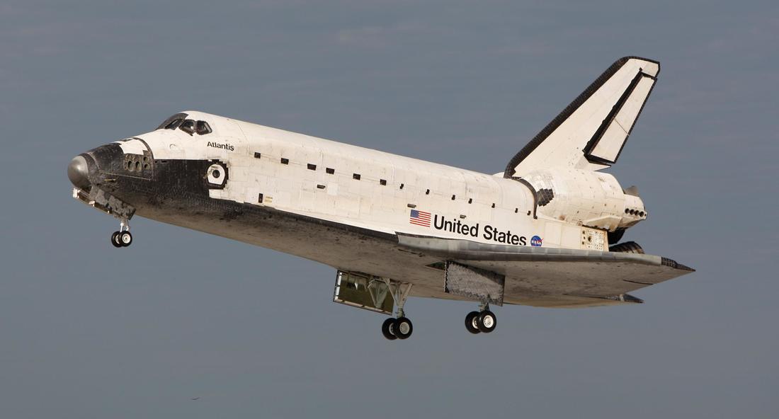
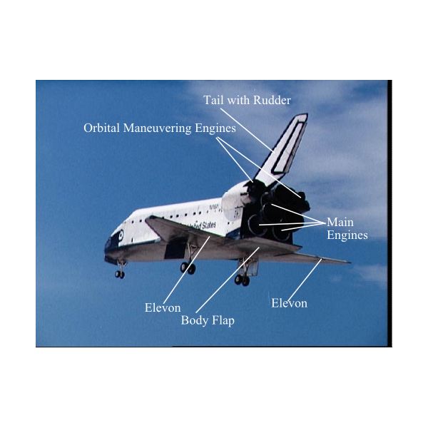
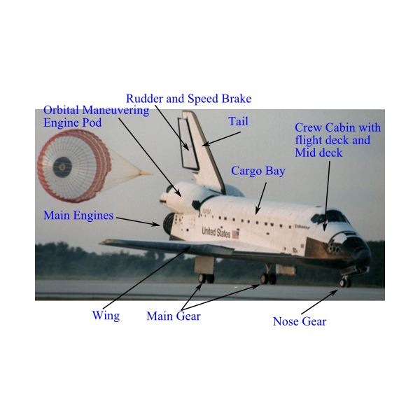
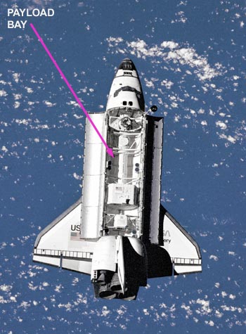
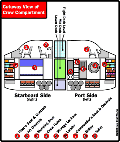
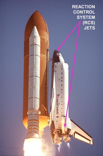
Now, let's look at where and how you will be living while you are in space. Orbiter The Orbiter is both the brains and heart of the Space Transportation System. The Orbiter contains the pressurized crew compartment (which can normally carry up to seven crew members), the huge cargo bay, and the three main engines mounted on its aft end. The Space Shuttle orbiter resembled an airplane in its design, with a standard-looking fuselage and two double delta wings, both swept wings at an angle of 81 degrees at their inner leading edges and 45 degrees at their outer leading edges. The vertical stabilizer of the orbiter had a leading edge that was swept back at a 45-degree angle. There were four elevons mounted at the trailing edges of the delta wings, and the combination rudder and speed brake was attached at the trailing edge of the vertical stabilizer. These, along with a movable body flap located underneath the main engines, controlled the orbiter during later stages of descent through the atmosphere and landing. The Reaction Control System (RCS)( RCS is a spacecraft system that uses thrusters to provide attitude control) was composed of 44 small liquid-fueled rocket thrusters and their very sophisticated computerized (fly-by-wire) flight control system, which utilized computationally intensive digital Kalman filtering. This control system carried out the usual attitude control along the pitch, roll, and yaw axes during all of the flight phases of launching, orbiting, and re-entry. This system also executed any needed orbital maneuvers, including all changes in the orbit's altitude, orbital plane, and eccentricity. These were all operations that required a lot more power and energy than mere attitude control. The forward rockets of the Reaction Control System, located near the nose of the Space Shuttle orbiter, included 14 primary and two vernier RCS rockets. The aft RCS engines were located in the two Orbital Maneuvering System (OMS) pods at the rear of the orbiter, and these included 12 primary (PRCS) and two vernier (VRCS) engines in each pod. The PRCS system provided the pointing control of the Orbiter, and the VRCS was used for fine maneuvering during the rendezvous, docking, and undocking maneuvers with the International Space Station, or formerly with the Russian Mir space station. The RCS also controlled the attitude of the orbiter during most of its re-entry into the Earth's atmosphere – until the air became dense enough that the rudder, elevons and body flap became effective. During the early design process of the orbiter, the forward RCS thrusters were to be hidden underneath retractable doors, which would open once the orbiter reached space. These were omitted in favor of flush-mounted thrusters for fear that the RCS doors would remain stuck open and endanger the crew and orbiter during re-entry The orbiter crew cabin consisted of three levels: the flight deck, the mid-deck, and the utility area. The uppermost of these was the flight deck, in which sat the Space Shuttle's commander and pilot, with up to two mission specialists seated behind them. The mid-deck, which was below the flight deck, had three more seats for the rest of the crew members. The galley, toilet, sleep locations, storage lockers, and the side hatch for entering and exiting the orbiter were also located on the mid-deck, as well as the airlock. The airlock had an additional hatch into the payload bay. This airlock allowed two or three astronauts, wearing their Extravehicular Mobility Unit (EMU) space suits, to depressurize before a walk in space (EVA), and also to repressurize and re-enter the orbiter at the conclusion of the EVA. The utility area was located under the floor of the mid-deck and contained air and water tanks in addition to the carbon dioxide scrubbing system. Electric power for the orbiter's subsystems was provided by a set of three hydrogen-oxygen fuel cells which produced 28 volt DC power and was also converted into 115 volt 400 Hz AC three-phase electric power (for systems that used AC power). These provided power to the entire Shuttle stack (including the SRBs and ET) from T-minus 3m30s up through the end of the mission. The hydrogen and oxygen for the fuel cells was kept in pairs of cryogenic storage tanks in the mid-fuselage underneath the payload bay liner, and a variable number of such tanks could be installed (up to five) depending on the requirements of the mission. The three fuel cells were capable of generating 21 kilowatts of power continuously (or a 15-minute peak of 36 kilowatts) with the orbiter consuming an average of about 14 kilowatts of that power (leaving 7 kilowatts for the payload). The orbiters were protected by Thermal Protection System (TPS) materials inside and out, from the Orbiter's outer surface to the payload bay. The TPS protected it from the cold soak of −121 °C (−186 °F) in space to the 1,649 °C (3,000 °F) heat of re-entry. The orbiter's structure was made primarily from aluminium alloy, although the engine thrust structure was made from titanium alloy. The later orbiters (Discovery, Atlantis and Endeavour) substituted graphite epoxy for aluminum in some structural elements in order to reduce weight. The windows were made of aluminum silicate glass and fused silica glass, and comprised an internal pressure pane, a 1.3-inch-thick (33 mm) optical pane, and an external thermal pane. The Space Shuttle orbiter had three sets of landing gear which emerged downwards through doors in the heat shield. As a weight-saving measure, the gear could not be retracted once deployed. Since any premature extension of the landing gear would very likely have been catastrophic (as it opened through the heat shield layers), the landing gear could only be lowered by manual controls, and not by any automatic system. Similarly, since the Shuttle landed at high speed and could not abort its landing attempt, the gear had to deploy reliably on the first try every time. The gear were unlocked and deployed by triple redundant hydraulics, with the gear doors actuated by mechanical linkages to the gear strut. If all three hydraulic systems failed to release the landing gear uplocks within one second of the release command, pyrotechnic charges automatically cut the lock hooks and a set of springs deployed the gear. Once in space, the shuttle orbiter is your home for seven to 14 days. The orbiter can be oriented so that the cargo bay doors face toward the Earth or away from the Earth depending upon the mission objectives; in fact, the orientation can be changed throughout the mission. One of the first things that the commander will do is to open the cargo bay doors to cool the orbiter. The orbiter consists of the following parts:
The crew compartment has three decks: Flight deck - uppermost deck
Living Environment The shuttle orbiter provides an environment where you can live and work in space. It must be able to do the following:
Life aboard the Space Shuttle The Space Shuttle was the first American spacecraft to have an Earth-like atmospheric mixture, 22% and 78%. For the Space Shuttle, NASA includes in the ECLSS category systems that provide both life support for the crew and environmental control for payloads. The orbiter must provide you with an environment similar to Earth. You must have air, food, water, and a comfortable temperature. The orbiter must also take away the wastes that your body produces (carbon dioxide, urine, feces) and protect you from fire. Let's look at these various aspects of the orbiter's life support system. On board the space shuttle, you need to have the following:
Five loops of fans circulate the atmosphere. The circulated air picks up carbon dioxide, heat and moisture:
Besides air, water is the most important quantity aboard the orbiter. Water is made from liquid oxygen and hydrogen in the space shuttle's fuel cells (the fuel cells can make 25 lb (11 kg) of water per hour). The water passes through a hydrogen separator to eliminate any trapped hydrogen gas (excess hydrogen gas is dumped overboard). The water is then stored in four water storage tanks located in the lower deck. Each tank can hold 165 lb (75 kg). The water tanks are pressurized by nitrogen so that water can flow to the mid-deck for use by the crew. Drinkable water is then filtered to remove microbes and can be warmed or chilled through various heat exchangers depending upon the use (food preparation, consumption, personal hygiene). Excess water produced by the fuel cells gets routed to a wastewater tank and subsequently dumped overboard. Outer space is an extremely cold environment and temperatures will vary drastically in different parts of the orbiter. You might think that heating the orbiter would be a problem. However, the electronic equipment generates more than enough heat for the ship. The problem is getting rid of the excess heat. So the temperature control system has to carry out two major functions:
Cold plates - metal plates that collect heat by direct contact with equipment or conduction Heat exchangers - collect heat from equipment using fluid. The equipment radiates heat to a fluid (water, ammonia) which in turn passes heat on to freon. Both fluids are pumped and recalculated to remove heat. Pumps, lines, valves - transport the collected heat from one area to another. Radiators - located on the inside surfaces of the cargo bay doors that radiate the collected heat to outer space. Flash evaporator/ammonia boilers - these devices are located in the aft fuselage and transfer heat from Freon coolant loops overboard when cargo bay doors are closed or when cargo bay radiators are overloaded. Flash evaporator Freon coolant loops wrap around an inner core. The evaporator sprays water on the heated core. The water evaporates removing heat. The water vapor is vented overboard. Ammonia boiler Freon coolant loops pass through a tank of pressurized ammonia. Heat released from the freon causes the ammonia to boil. Ammonia vapor is dumped overboard. The cabin heat exchanger also controls the cabin temperature. It circulates cool water to remove excess heat (cabin air is also used to cool electronic equipment) and transfers this heat to a Freon exchanger. The Freon then transfers the heat to other orbiter systems (e.g., cryogenic gas tanks, hydraulic systems) and radiates excess heat to outer space. The orbiter has internal fluorescent floodlights that illuminate the crew compartment. The orbiter has external floodlights to illuminate the cargo bay. Finally, the control panels are lighted internally for easy viewing. Food is stored on the mid-deck of the crew compartment. Food comes in several forms (dehydrated, low moisture, heat-stabilized, irradiated, natural and fresh). The orbiter has a galley-style kitchen module along the wall next to the entry hatch, which is equipped with the following:
Like any home, the orbiter must be kept clean, especially in space when floating dirt and debris could present a hazard. Wastes are made from cleaning, eating, work and personal hygiene. For general house cleaning, various wipes (wet, dry, fabric, detergent and disinfectant), detergents, and wet/dry vacuum cleaners are used to clean surfaces, filters and the astronauts. Trash is separated into wet trash bags and dry trash bags, and the wet trash is placed in an evaporator that will remove the water. All trash bags are stowed in the lower deck to be returned to Earth for disposal. Solid waste from the toilet is compacted, dried and stored in bags where it is returned to Earth for disposal (burning). Liquid waste from the toilet goes to the wastewater tank where it is dumped overboard. Fire is one of the most dangerous hazards in space. The orbiter has a Fire Detection and Suppression Subsystem that consists of the following:
After a fire is extinguished, the atmosphere control system will filter the air to remove particulates and toxic substances. Next, we'll look at the technologies that help the space shuttle navigate, change direction and communicate from space. Space Shuttle Positioning, Communication and Navigation To change the direction that the orbiter is pointed (attitude), you must use the reaction control system (RCS) located on the nose and Orbital Maneuvering System pods of the aft fuselage. The RCS has 14 jets that can move the orbiter along each axis of rotation (pitch, roll, and yaw). The RCS thruster’s burn monomethyl hydrazine fuel and nitrogen tetroxide oxidizer just like the OMS engines described previously. Attitude changes are required for deploying satellites or for pointing (mapping instruments, telescopes) at the Earth or stars. To change orbits (e.g., rendezvous, docking maneuvers), you must fire the OMS engines. As described above, these engines change the velocity of the orbiter to place it in a higher or lower orbit. Flight systems The Shuttle was one of the earliest craft to use a computerized fly-by-wire digital flight control system. This means no mechanical or hydraulic linkages connected the pilot's control stick to the control surfaces or reaction control system thrusters. The control algorithm, which used a classical Proportional Integral Derivative (PID) approach. The Shuttle's fly-by-wire digital flight control system was composed of 4 control systems each addressing a different mission phase: Ascent, Descent, On-Orbit and Aborts. The Shuttle's Nose Wheel Steering Control Algorithm that allowed the Orbiter to safely land at Kennedy Space Center's Shuttle Runway. A concern with using digital fly-by-wire systems on the Shuttle was reliability. Considerable research went into the Shuttle computer system. The Shuttle used five identical redundant IBM 32-bit general purpose computers (GPCs), model AP-101, constituting a type of embedded system. Four computers ran specialized software called the Primary Avionics Software System (PASS). A fifth backup computer ran separate software called the Backup Flight System (BFS). Collectively they were called the Data Processing System (DPS). The design goal of the Shuttle's DPS was fail-operational/fail-safe reliability. After a single failure, the Shuttle could still continue the mission. After two failures, it could still land safely. The four general-purpose computers operated essentially in lockstep, checking each other. If one computer provided a different result than the other three (i.e. the one computer failed), the three functioning computers "voted" it out of the system. This isolated it from vehicle control. If a second computer of the three remaining failed, the two functioning computers voted it out. A very unlikely failure mode would have been where two of the computers produced result A, and two produced result B (a two-two split). In this unlikely case, one group of two was to be picked at random. The Backup Flight System (BFS) was separately developed software running on the fifth computer, used only if the entire four-computer primary system failed. The BFS was created because although the four primary computers were hardware redundant, they all ran the same software, so a generic software problem could crash all of them. Embedded system avionic software was developed under totally different conditions from public commercial software: the number of code lines was tiny compared to a public commercial software product; changes were only made infrequently and with extensive testing, and many programming and test personnel worked on the small amount of computer code. However, in theory it could have still failed, and the BFS existed for that contingency. While the BFS could run in parallel with PASS, the BFS never engaged to take over control from PASS during any Shuttle mission. The software for the Shuttle computers was written in a high-level language called HAL/S. It is specifically designed for a real time embedded system environment. The IBM AP-101 computers originally had about 424 kilobytes of magnetic core memory each. The CPU could process about 400,000 instructions per second. They had no hard disk drive, and loaded software from magnetic tape cartridges. In 1990, the original computers were replaced with an upgraded model AP-101S, which had about 2.5 times the memory capacity (about 1 megabyte) and three times the processor speed (about 1.2 million instructions per second). The memory was changed from magnetic core to semiconductor with battery backup. Tracking and Communication You must be able to talk with flight controllers on the ground daily for the routine operation of the mission. In addition, you must be able to communicate with each other inside the orbiter or its payload modules and when conducting spacewalks outside. NASA's Mission Control in Houston will send signals to a 60 ft radio antenna at White Sands Test Facility in New Mexico. White Sands will relay the signals to a pair of Tracking and Data Relay satellites in orbit 22,300 miles above the Earth. The satellites will relay the signals to the space shuttle. The system works in reverse as well. The orbiter has two systems for communicating with the ground:
The orbiter has several intercom plug-in audio terminal units located throughout the crew compartment. You will wear a personal communications control with a headset. The communications control is battery-powered and can be switched from intercom to transmit functions. You can either push to talk and release to listen or have a continuously open communication line. To talk with spacewalkers, the system uses a UHF frequency, which is picked up in the astronaut's space suit. The orbiter also has a series of internal and external video cameras to see inside and outside. Navigation, Power and Computers The orbiter must be able to know precisely where it is in space, where other objects are and how to change orbit. To know where it is and how fast it is moving, the orbiter uses global positioning systems (GPS). To know which way it is pointing (attitude), the orbiter has several gyroscopes. All of this information is fed into the flight computers for rendezvous and docking maneuvers, which are controlled in the aft station of the flight deck. All of the on-board systems of the orbiter require electrical power. Three fuel cells make electricity; they are located in the mid fuselage under the payload bay. These fuel cells combine oxygen and hydrogen from pressurized tanks in the mid fuselage to make electricity and water. Like a power grid on Earth, the orbiter has a distribution system to supply electrical power to various instrument bays and areas of the ship. The water is used by the crew and for cooling. The orbiter has five on-board computers that handle data processing and control critical flight systems. The computers monitor equipment and talk to each other and vote to settle arguments. Computers control critical adjustments especially during launch and landing:
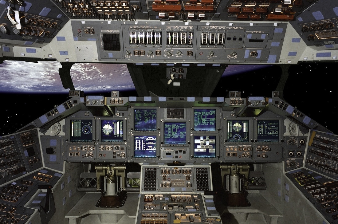
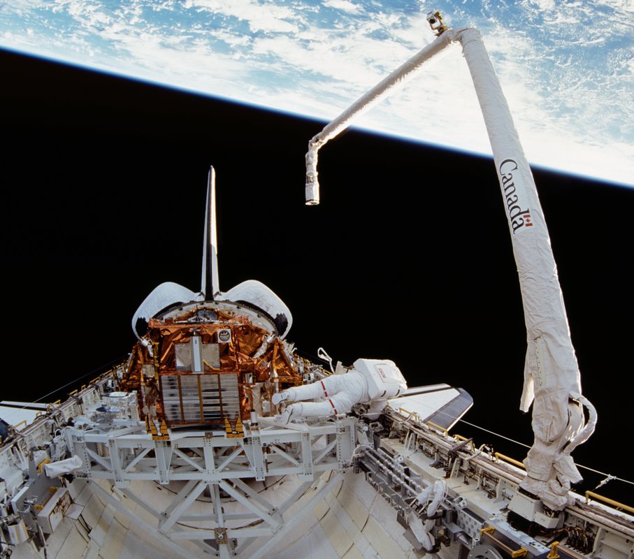
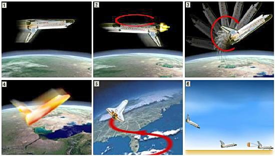
Pilots essentially fly the computers, which fly the shuttle. To make this easier, the shuttles have a Multifunctional Electronic Display Subsystem (MEDS), which is a new, full color, flat, 11-panel display system. The MEDS, also known as the "glass cockpit", provides graphic portrayals of key light indicators (attitude, altitude, speed). The MEDS panels are easy to read and make it easier for shuttle pilots to interact with the orbiter. Now let's look at the kind of work you'll be doing during your shuttle mission. Work aboard the Shuttle The shuttle was designed to deploy and retrieve satellites as well as deliver payloads to low Earth orbit (The Shuttle is designed to reach orbits ranging from about 185 kilometers to 643 kilometers). To do this, the shuttle uses the Remote Manipulator System (RMS). The RMS was built by Canada and is a long arm with an elbow and wrist joint. The Shuttle Remote Manipulator System (SRMS), also known as Canadarm is a series of robotic arms that were used on the Space Shuttle orbiters to deploy, maneuver and capture payloads. After the Space Shuttle Columbia disaster, the Canadarm was always paired with the Orbiter Boom Sensor System (OBSS), which was used to inspect the exterior of the Shuttle for damage to the system. You can control the RMS from the aft flight deck. The RMS can grab payloads (satellites) from the cargo bay and deploy them, or grab on to payloads and place them into the bay. The original Canadarm was capable of deploying and retrieving payloads weighing up to 332.5 kg (733 lb) in space. In the mid-1990s the arm control system was redesigned to increase the payload capability to 3,293 kg (7,260 lb) in order to support space station assembly operations. While able to maneuver payloads with the mass of a loaded bus in space, the arm motors cannot lift the arm's own weight when on the ground. The basic Canadarm configuration consists of a manipulator arm, a Canadarm display and control panel, including rotational and translational hand controllers at the orbiter aft flight deck flight crew station, and a manipulator controller interface unit that interfaces with the orbiter computer. Most of the time, the arm operators see what they are doing by looking at the Advanced Space Vision System screen next to the controllers. One crew member operates the Canadarm from the aft flight deck control station, and a second crew member usually assists with television camera operations. This allows the Canadarm operator to view Canadarm operations through the aft flight deck payload and overhead windows and through the closed-circuit television monitors at the aft flight deck station. The Canadarm is outfitted with an explosive-based mechanism to allow the arm to be jettisoned. This safety system allows the Orbiter's payload bay doors to be closed in the event that the arm fails in an extended position and is not able to be retracted. The Canadarm is 15.2 m (50 ft) long and 38 cm (15 in) diameter with six degrees of freedom. It weighs 410 kg (900 lb) by itself, and 450 kg (990 lb) as part of the total system. The Canadarm has six joints that correspond roughly to the joints of the human arm, with shoulder yaw and pitch joints, an elbow pitch joint, and wrist pitch, yaw, and roll joints. The end effector is the unit at the end of the wrist that grapples the payload's grapple fixture. The two lightweight boom segments are called the upper and lower arms. The upper boom connects the shoulder and elbow joints, and the lower boom connects the elbow and wrist joints. In the past, the shuttle was used for delivering satellites and conducting experiments in space. Within the mid-deck, there are racks of experiments to be conducted during each mission. When more space was needed, the mission used the Spacelab module, which was built by the European Space Agency (ESA). It fit into the cargo bay and was accessed by a tunnel from the mid-deck of the crew compartment. It provided a "shirt-sleeve" environment in which you could work. The Spacelab was lost along with Columbia in 2003. Now, most experiments will be conducted aboard the International Space Station. The shuttle's major role is building and resupplying the International Space Station. The shuttle delivers components built on Earth. Astronauts use the RMS to remove components from the cargo bay and to help attach them to existing modules in space station. You will spend most of your time on the shuttle doing work to accomplish the mission objectives. Besides work, you must exercise frequently on the treadmill to counteract the loss of bone and muscle mass associated with weightlessness. You will also eat at the galley and sleep in your bunk-style sleeping quarters. You will have a toilet and personal hygiene facilities for use. You may have to perform spacewalks to accomplish the mission objectives. This will involve getting into a space suit and going through depressurization procedures in the airlock. When your mission objectives have been accomplished, it will be time to return to Earth. Let's look at this process in the next section. The Shuttle's Return to Earth For a successful return to Earth and landing, dozens of things have to go just right. First, the orbiter must be maneuvered into the proper position. This is crucial to a safe landing. When a mission is finished and the shuttle is halfway around the world from the landing site (Kennedy Space Center, Edwards Air Force Base), mission control gives the command to come home, which prompts the crew to:
Because it is moving at about 17,000 mph (28,000 km/h), the orbiter hits air molecules and builds up heat from friction (approximately 3000 degrees F, or 1650 degrees C). The orbiter is covered with ceramic insulating materials designed to protect it from this heat. The materials include:
Maneuvering of the orbiter for re-entry These materials are designed to absorb large quantities of heat without increasing their temperature very much. In other words, they have a high heat capacity. During re-entry, the aft steering jets help to keep the orbiter at its 40 degree attitude. The hot ionized gases of the atmosphere that surround the orbiter prevent radio communication with the ground for about 12 minutes (i.e., ionization blackout). When re-entry is successful, the orbiter encounters the main air of the atmosphere and is able to fly like an airplane. The orbiter is designed from a lifting body design with swept back "delta" wings. With this design, the orbiter can generate lift with a small wing area. At this point, flight computers fly the orbiter. The orbiter makes a series of S-shaped, banking turns to slow its descent speed as it begins its final approach to the runway. The commander picks up a radio beacon from the runway (Tactical Air Navigation System) when the orbiter is about 140 miles (225 km) away from the landing site and 150,000 feet (45,700 m) high. At 25 miles (40 km) out, the shuttle's landing computers give up control to the commander. The commander flies the shuttle around an imaginary cylinder (18,000 feet or 5,500 m in diameter) to line the orbiter up with the runway and drop the altitude. During the final approach, the commander steepens the angle of descent to minus 20 degrees (almost seven times steeper than the descent of a commercial airliner). Shuttle flight path for landing When the orbiter is 2,000 ft (610 m) above the ground, the commander pulls up the nose to slow the rate of descent. The pilot deploys the landing gear and the orbiter touches down. The commander breaks the orbiter and the speed brake on the vertical tail opens up. A parachute is deployed from the back to help stop the orbiter. The parachute and the speed brake on the tail increase the drag on the orbiter. The orbiter stops about midway to three-quarters of the way down the runway. After landing, the crew goes through the shutdown procedures to power down the spacecraft. This process takes about 20 minutes. During this time, the orbiter is cooling and noxious gases, which were made during the heat of re-entry, blow away. Once the orbiter is powered down, the crew exits the vehicle. Ground crews are on-hand to begin servicing the orbiter. Source/Reference
Leave a Reply. |
AuthorPalash Choudhari Archives
June 2021
Categories
All
|
 RSS Feed
