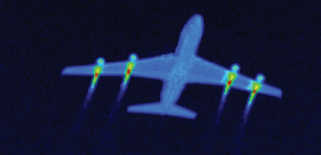
 Fuselage IR radiance consist of emission by virtue of its temperature, reflected earth shine, sky shine & sun light. For a low flying aircraft, even if the rear fuselage emissivity is made zero, the air craft can still be locked on by SAM, due to the reflected earth shine in 8-12 micrometer. In the absence of earth shine, negative contrast with the background sky radiance can be used for air craft detection & lock on. Matching of fuselage IR emissions with those of the background is a high potential technique for IR camouflage. The IRSS system for fuselage can be grouped in 2 categories
AIRCRAFT SKIN HEATING/COOLING Air craft uses a system for electrical heating of the upper portion of the fuselage for background matching. The negative IR contrast of the aircraft with respect to the surroundings is minimized there by providing IR camouflage when viewed by aircraft flying at higher altitudes. However heating is less often applicable; instead cooling of the aerodynamically heated fuselage skin especially at high mach no is more often applicable. Cooling of the skin to a temperature near the ambient air will reduce the detection range by IR imaging scanners. Heat pipe cooling & liquid evaporative cooling of aircraft skin from inside & heating/cooling of surfaces by thermo couples were patented as IRSS system. In such systems the background temperature is sensed & the aircraft skin heated/ cooled to the same temperature resulting in IR camouflage. The skin is heated or cooled using a thermo electric module that converts electrical energy into a temperature gradient. By application of voltage across the modules one side of the module becomes hot & the other side becomes cold. The temperature of the adjacent surface can be controlled by varying the applied voltage.  EMISSIVITTY OPTIMIZATION The aircrafts IR radiance strongly depends on the emissivity of the radiating surface; which depends on surface temperature & surface physical & chemical properties. Most methods of IRSS are associated with performance penalties e.g. Increased drag, additional weight, increased RCS; increased nozzle back pressure etc. emissivity optimization of the aircraft surface is a viable option which does not impose performance penalties. Rear fuselage emissivity optimization in the 3-5 & 8-12 band emissivity reduction from 1.0 to 0.0 reduces peak aircraft spectral lock on range by almost 100% in the 8-12 micrometer bands. It is seen that lock on range is more sensitive in 8-12 band as compared to 3-5 band. Emissivity can be optimized by physical & chemical treatment of the radiating surfaces. SOME TECHNIQUES TO EMISSIVITY OPTIMIZATION
  LIMITATIONS OF IR SUPPRESSORS Passive IRCM’s can be incorporated on an aircraft in the initial design or modification stage or later as retrofits/additives. First gen IR suppressors were simple & aimed to provide optical blockage of hot engine parts. 2nd gen IR suppressors involve a combination of optical blockage, metal cooling & exhaust gas cooling which add more complexity to the system. The major performance penalties associated with incorporation of IR suppressors are disclosed below
 ACTIVE COUNTER MEASURES These countermeasures include IR jammers and IR flares, which serve as decoys by luring away the approaching heat seeking missile. Saturation jammers introduce large amount of IR noise into the threat’s tracking system that damages the seeker optics. Smart jammers are either non-directional or directional (DIRCM), and deceive IR trackers by sending false target information. The IR flares were used first as active countermeasures against IR seekers in the Vietnam War in the 1960s. These decoys are easy to handle, reliable, and are made of cheap constituents like metal fuels and oxidizers. To imitate the tail-pipe IR spectrum, the decoy flares fired from the rear. Busting smoke of bronze–copper-lined flakes, bronze flakes, and mixture of flakes with chaff, serve as IR decoys for longer duration .However, the new generation of imaging IR detectors can discriminate IR flare (as point source) and target, making flares ineffective as IRCM. To counter this situation, decoys driven by liquid fuels that produce as large a radiating plume as that of aircraft were proposed. Such decoys use more energetic fuels like tri-ethyl-aluminum, tri-isobutyl-aluminum, di-ethyl-aluminum, etc., which are called as pyrophoric liquids Development of a Missile Approach Warning System (MAWS) against IR-guided missiles is a formidable task. Typical MAWS should ideally have the following characteristics:
There are three technological options available for MAWS
 COUNTER COUNTER MEASURES CCMs are counter the active and passive IRCMs. Some examples of CCM are as follows
 Leave a Reply. |
AuthorPalash Choudhari Archives
June 2021
Categories
All
|
 RSS Feed
