|
Scan pattern referring to how radars steer their beam across their field of view to search for targets CIRCULAR SCAN A circular scanning radar uses an antenna system that continuously scans 360° in azimuth . The time required for the antenna to sweep one complete 360° cycle is called the scan rate. Scan duration is the number of “hits per scan,” or the number of pulses, reflected by a target as the radar beam crosses it during one full scan. Most pulse radars require 15 to 20 hits per scan to obtain sufficient information to display a target. The factors that determine the number of hits per scan the radar receives include pulse repetition frequency (PRF), antenna beamwidth, and scan duration. Circular scan radars provide accurate target range and azimuth information. This makes these radars ideal for the roles of early warning and initial target acquisition. To accomplish these missions, the antenna generates a fan beam that has a large vertical beamwidth and a small horizontal beamwidth. Since elevation information will normally be provided by height finder radars, the size of the vertical beamwidth is not a limitation. This antenna scan allows the radar to scan large volumes of airspace for early target detection. Since early detection is the primary goal of early warning radars, accurate altitude and azimuth resolution are secondary considerations. Circular scan radars designed for early warning transmit a radar signal with a low PRF. A low PRF allows sufficient time for the radar pulse to travel long distances, and return, before another pulse is transmitted. This gives the radar system a long, unambiguous range capability. Circular scan radars with low PRFs generally use long pulse widths in order to increase their average power and long-range detection capability. The scan durations of early warning radars are relatively long to provide the required “hits per scan” for long-range target detection. The plan position indicator (PPI) scope display is normally used with circular scan radar In order to provide coverage for a large volume of airspace, the beamwidth associated with circular scan radar is relatively wide. This wide beamwidth, coupled with the long pulse width and low PRF, gives the circular scan radar a large resolution cell, especially at long ranges. This limitation can be exploited to mask force size and composition. However, as range decreases, the dimensions of the resolution cell decrease, and circular scan radar will begin to break out target formations. Circular scan radars provide range and azimuth information for both early warning and acquisition roles. Modified circular scan radars that can also provide elevation information may be used for ground control intercept (GCI) roles. Two modified circular scan radars that determine range, azimuth, and elevation are the V-beam and the stacked beam. The V-beam radar transmits two fan-shaped beams that are swept together. A vertical beam provides range and azimuth information. A second beam, rotated at some convenient angle, provides a measure of the altitude of the target. A stacked beam radar employs a vertical stack of fixed elevation “pencil” beams which rotate 360°. Elevation information is obtained by noting which beam contains the target return. Range and azimuth information is determined in the same manner as in an early warning radar. 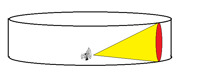 LINEAR SCAN Linear scan is a method used by some radar systems to sweep a narrow radar beam in a set pattern to cover a large volume of airspace. Linear scans can be oriented in a vertical direction for height finder radars or in a horizontal direction, or raster, for acquisition and target tracking radars. Unidirectional linear radar scans in a single direction then begins its sweep all over again. Generally, linear scans offer excellent single-axis coverage, and the narrow beam offers enhanced azimuth and elevation resolution. UNIDIRECTIONAL SCAN A helical scan is a unidirectional scan pattern that allows a “pencil” beam to search a 360° pattern. The antenna sweeps a 360° sector in a clockwise direction. After each complete revolution, the antenna elevation is increased. This scan pattern is repeated for a specified number of revolutions, in this case, three, 360° sweeps. At the end of the scan pattern, the antenna elevation is reset to the initial elevation and the scan is repeated. A helical scan pattern is commonly used as a target acquisition mode for radar systems with narrow vertical and horizontal beamwidths. BIDIRECTIONAL SCAN A bidirectional linear scan, such as a raster scan, sweeps both horizontally and vertically. A raster scan uses a thin beam to cover a rectangular area by horizontally sweeping the area. The angle of elevation is incrementally stepped up or down with each horizontal sweep of the desired sector. After the sector has been covered, the angle of elevation is reset to the original value and the process is repeated. The number of raster bars is set by the number of horizontal sweeps in the basic raster pattern. Shows a four-bar raster scan, which is normally associated with airborne interceptor (Al) radar. 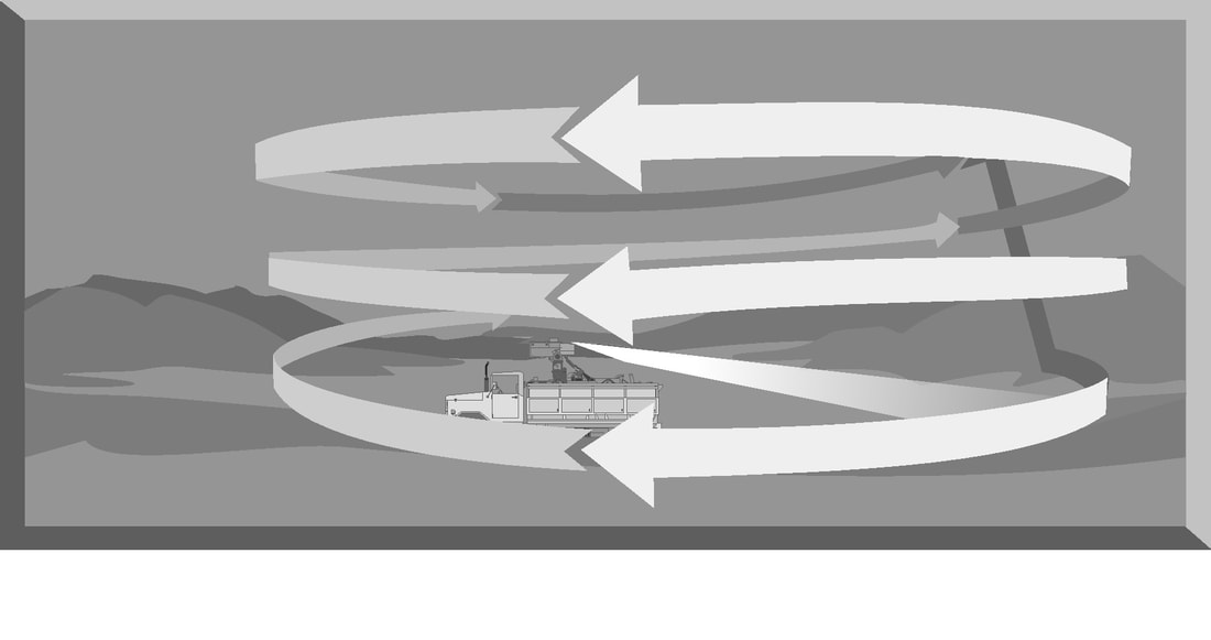 CONICAL SCAN A conical scan, or conscan, radar is generally used for precision target tracking. A conical scan radar employs a pencil beam of radar energy that is continuously rotated around the target. This circular rotation of a pencil beam generates a cone-shaped scan pattern with the apex of the cone located at the antenna. Thus, the name conical scan. As the pencil beam rotates, the circular scan patterns overlap in the center. This creates a central tracking area that has a much smaller effective beamwidth than the rotating pencil beam. This results in a very precise tracking solution. Since conical scan radars are designed for precision target tracking, these radars normally operate at high frequencies, high PRF, narrow pulse widths, and narrow beamwidths. The rotation rate of the pencil beam can exceed 1,800 revolutions per minute. This means that both azimuth and elevation data can be updated about 30 times per second. 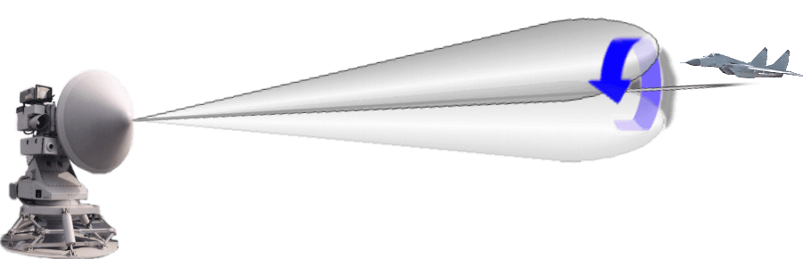 The combination of conical scan and raster scan is called a Palmer-raster scan. A Palmer-raster scan uses a thin beam, employing a conical scan searching pattern, for a specific sector of airspace. With each sweep of the sector, the angle of elevation is incrementally stepped up or down. After the vertical sector has been covered, the angle of elevation is set at the original elevation and the process is repeated. The number of bars is determined by the number of vertical search scans. 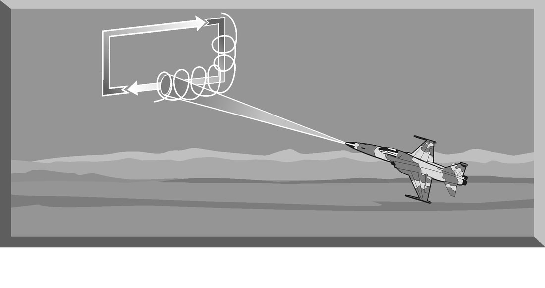 The combination of a conical scan and a circular scan is called a Palmer scan. Palmer scans incorporate a circular scanning antenna to search the entire horizon while simultaneously performing a conical scan. If the radar antenna is also performing a unidirectional altitude search in conjunction with this scan, it is employing a Palmer-helical scan. TRACK-WHILE-SCAN A track-while-scan (TWS) system uses a technique that allows a radar to track one or more targets while scanning for others. Radar systems with a TWS capability must be able to generate two or more distinct radar beams. A conventional TWS radar employs two antennas that work with each other to perform the scan function . Each antenna produces a separate unidirectional beam. Each beam is transmitted at a different frequency. The vertical antenna generates a beam employing a vertical sector scan similar to height finder radar except the beamwidth is narrower and it scans at a higher rate. The horizontal antenna generates an identical beam employing a horizontal sector scan at a different frequency. The track function is accomplished in the area where the two beams pass through each other. A target that is within this center area is tracked and positional information on range, elevation, and azimuth is updated each time the beams sweep through the area. The phased array radar is a product of the application of computer and digital technologies to the field of radar design. A phased array is a complex arrangement of many individual transmitting and receiving elements in a particular pattern. Common arrays include linear, planar, curved, and conformal, with linear being the most common. By using a computer to rapidly and independently control groups of these individual elements, a phased array antenna can, in effect, radiate more than one beam from the antenna. Multiple beams and computer processing of radar returns give the phased array radar the ability to perform the TWS function. The most common employment of the TWS capability of the phased array radar is in the air-to-air arena. 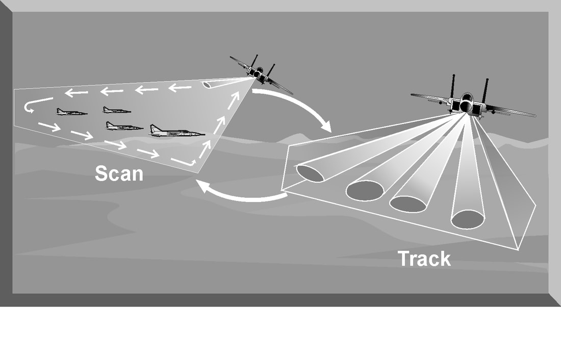 The number of individual transmitting and receiving elements is limited by the size of the radar antenna. The number of targets phased array radar can track is limited by the number of independent beams the antenna can generate. Many phased array radars, especially air-to-air radars, do not track and scan simultaneously, but rapidly switch between the two modes to overcome this limitation. Modern TWS radars employ computer signal processing and complex computer algorithms to simplify the problem of target correlation. Air-to-air radar typically uses a raster scan to search a volume of airspace. In the search mode, the radar simply presents all targets detected in this airspace to the pilot on his radar display. In the TWS mode, the radar employs computer processing to figure out target correlation and update target information. This is done automatically, and the results are presented on the display. Track-before-detect In radar technology and similar fields, track-before-detect (TBD) is a concept according to which a signal is tracked before declaring it a target. In this approach, the sensor data about a tentative target are integrated over time and may yield detection in cases when signals from any particular time instance are too weak against clutter (low signal-to-noise ratio) to register a detected target. The TBD approach may be applied both for pure detection when the tentative target displays a very small amount of apparent motion, as well as for actual motion tracking. In the first case the problem is considerably simpler, both in terms of the amount of calculation and the complexity of algorithms
Suneer
1/8/2021 09:27:58 pm
Excellent article. I found many required information here in one single article in a concise form.. Thank you.. Leave a Reply. |
AuthorPalash Choudhari Archives
June 2021
Categories
All
|
 RSS Feed
