|
This article covers India’s quest for rocket artillery systems in detail. 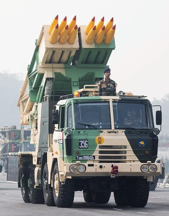 Pinaka MBRL The usage of rocket artillery dates back to India’s 1857 revolt against the British when Tipu Sultan used rockets tipped with blades. These rockets had metal casings and had a range of about 2kms. The blades used to randomly roll over the troops cutting them and inflicting heavy damages over them. Soon with rockets various aiming mechanisms, propellants, warheads as well as mobility systems began to develop along with modern artillery rocket systems. Conventionally the terrain in which Indian Army usually has to fight it's battles still uses gun based artillery systems. Throughout the world it is a debatable matter whether rocket based artillery is better or gun based. Whenever battles had to be fought for sustained longer runs gun based artillery is preferred, and if a fast attack is to be performed for movement of troops in a short term high intensity war, then rocket based artillery is used. 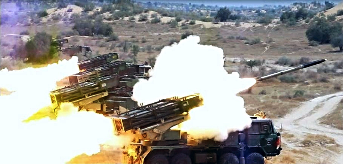 The name pinaka comes from the sacred trident owned by hindu god shiva. shiva's pinaka trident is his main weapon. Introduction.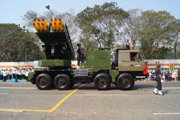 Pinaka MBRL was developed in India after the requirement of an indegeneous system to complement as well as replace the Russian Smerch and BM-21 Grad. The earliest introduction to modern Indian Military and DRDO of the artillery rockets came in the form of BM-21. There was no background information about the usage of artillery rockets in Warfare, no knowledge of materials and propellants, non availability of manufacturing expertise. The only visible option available was to reverse engineer available BM-21 Grad rockets and build a base of everything upon that. The emphasis was on the development of technologies related to rocket propellent, ammunition re-supply chain, warhead fuzes, launching mechanism. Organisations like HEMRL, PXE and ARDE were raised in the following process. What is an Artillery Rocket System???An Artillery system that uses rockets as a means to hurl projectiles at enemy troops. As described in the introduction the usage of artillery rockets have been a huge force multiplier for the military. In modern times locating enemy artillery and directing our artillery fire precisely at the positions of the enemy's artillery to neutralise their artillery even before they could act has become a useful tactic. In modern India when indegeneous rocket artillery development began there was no available literature about usage artillery in warfare or computational tools to test and calculate models. The Artillery Rocket System is used to inflict heavy damage on enemy in a short period of time. It is used on an enemy which is large in volume but has a relatively lower degree of protection. It is not used for sustained hours and hours of battles and is very costly if an enemy is pushing small volumes of troops and is using guerrilla warfare techniques. then rocket Artillery is not suitable against such force. 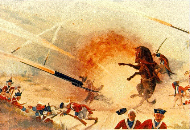 What is an Artillery Rocket??It actually depends upon whom you ask and which country you are. But in India, We have a very vague classification of Rockets. A propellant powered cylindrical casing which is unguided and delivers payload is a rocket. A propellant powered cylindrical casing which is guided but delivers payloads in space is an SLV (Satellite Launch Vehicle). A propellent powered cylindrical casing which delivers ammunition as a payload in enemy territory through a ballistic trajectory is a missile. Rockets have a high rate of collateral damage since their launch creates a lot of hot gases around the launch site, also it alerts the enemy quickly. Since rockets are unguided they are also inaccurate. A rocket consists of various subsystems which has to perform its tasks in sync for the sake of accuracy to reduce collateral damage and increase accuracy. ARDE has developed guided Pinaka rockets that have a GNC ( Guidance cum Navigation and Control kit). The subsystem of a rocket comprises the following. 1 Propulsion System 2 Rocket Fuzes 3 Stabiliser System 4 Warhead 5 GNC ( only in guided rockets) 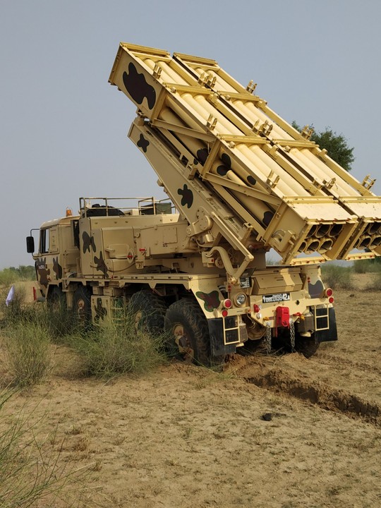 Design.The Design is a complex engineering process involving user requirements and analysis of Battlefield various scenarios. Analysis is carried out considering various aspects such as aerodynamics, propulsion, structural integrity and trajectory simulation, etc. The vibrations caused during multiple launches of rockets their firing order, their firing intervals also affect their performance. The whole design process of a system has to take all these things into consideration. The control system has to consider the errors that occur due to aerodynamic instability as well as vibrations during launch, elasticity of the structure, etc. 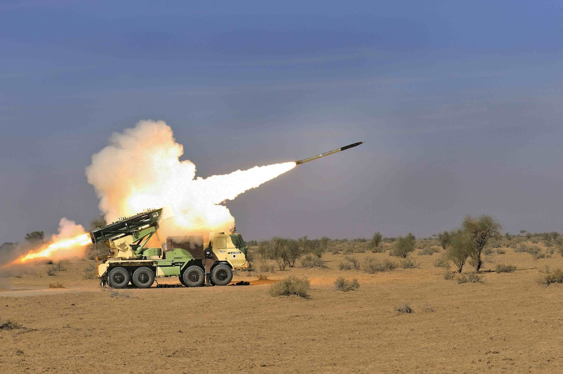 The entire launching mechanism as well as the rocket itself is analysed for heating. Structural analysis is performed on rocket casing and especially on the stabiliser so that smooth functioning could be performed. It has been optimised that if firing order and firing intervals are properly computed then for a certain target area at a certain rate dispersion can be reduced and hence accuracy can be increased. For doing this supportive tools in the Pinaka battery configuration are needed. All these optimisations are performed for a particular variant during design phase only. Due to geometrical and mass constraints rockets are designed with high slenderness ratio (L/D ~21) and multiple joints which reduces structural stiffness. Hence, rockets are susceptible to aero elastic problems like body divergence and fin flutter. Apart from aerodynamic loads, rocket structure subjected to internal chamber pressure due to propellant burning and ignition transient. 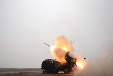 1 Propulsion Systems.Since these rockets are stored in containers and used occasionally it is obvious that Solid Propellants would be used in them. The propulsion system which uses Solid Propellants comprises of a cylindrical casing enclosing a propellant grain, a combustor/igniter at either ends of the cylinder and a nozzle to force out hot gases burnt after combustion. The igniter can be mounted either at the nozzle end or at head end. There can be one or many nozzles. The shape of the cross section of propellant grain is very significant, because it influences the manner in which burning would take place. When ignited, the propellant grain burns out radially outward forcing the hot gases through nozzle. The nozzles are designed to maintain some level of chamber pressure inside the casing, and casing design should also be in accordance to that. This video properly explains Solid Rocket Propulsion. A must watch. In India the most widely used propellant in Agni, Astra Missiles or PSLV rockets is HTPB. Hydroxyl Terminated Poly-Butadine HTPB is a very interesting fuel.HTPB is a mixture rather than a pure compound. It binds the oxidizing agent and other ingredients into a solid but elastic mass. The cured polyurethane acts as a fuel in such mixtures. It is used by ISRO’s PSLV and also Japanese SLV called M5. Being developed in various forms since the 1960s in India, The Composite Propellent used in Pinaka consists of HTPB, ammonium perchlorate and aluminium powder as major ingredients. The bonding agent, plasticizer and processing aid curing agent of undisclosed type is also used. These propellants hacked from the Soviet Rocket industry have high specific impulse and high density. The Pinaka Mk1, Mk2 and 122MM ER Rockets use this propellent. However better propellent is being pursued. The Composite Modified Double Base propellent is known to provide better specific impulse than the Composite Propellant currently used. The CMDB has more oxidiser compounds dispersed in it.  The Propellant Grain is either cartridge loaded or case bonded. The cartridge loaded ones are manufactured separately and then assembled into the casing while case bonded ones the casing is used as a mould and propellant is cast directly inside the case. The propellent can be manufactured by using either casting-moulding or could be extruded. While Pinaka Mk-I utilizes cartridge loaded grain, Pinaka Mk-II/ERR122 utilizes case bonded grain. For case bonded rockets the new propellant being developed is Nitrate Ester Plasticized Polyether (NEPE) propellant having high energy, high density and superior low temperature strain capability.  The Rocket motor casing is designed to be light weight as well as strong enough to sustain the chamber pressure experienced during burning of propellent. There are other aerodynamic loads that are exerted on the casing while following a ballistic trajectory cutting through air at very high speeds. The design of casing must take these loads into consideration too. Finally the available most easy and cost effective manufacturing technique should be used and selected material should be suitable to such a process. The thick hollow cylindrical casings are usually manufactured using a process called 'Flow Forming’. Flow Forming is a process by which low strength, low cost material can be formed into high strength, and more precise cylindrical casing tubes with considerably reduced mass. Flow forming is also suitable for mass production of such tube casings. In the Flow Forming process, a tube of metal is formed over a mandrel by one or more rollers using tremendous pressure. The roller deforms the workpiece, forcing it against the mandrel, both axially lengthening and radially thinning it. The entire process is cold worked, meaning the workpiece isn't heated additionally. The workpiece does get heated due to friction, because of which coolant fluids are constantly poured over it. Most of the time additional machining is even not required, just some finishing work might be needed. This is why this process does not produce wastage. Video of Flow Forming Process The material used in Pinaka is ESR grade AISI 4130 steel forging. This material though needs some heat treatment before forming to attain necessary mechanical properties.The required range of pre-form hardness, grain size and percentage thickness reduction meets the specified strength levels of rocket motor. Effect of various flow forming parameters like spindle speed, roller feed rate, roller geometric features like approach angle and roller nose radius were also studied and operating parameters for the flow forming of rocket motor were established. Thus the entire propellent system comprising of casing, igniter and propellant is a complex assembly of parts made out of careful manufacturing processes. All these elements are procured from private industries thus creating indegeneous defence industry. 2 Rocket Fuzes.The Fuzes are a combination of sensors and detonators, the sensors sense a set necessary condition needed for explosion to happen and the detonator causes the explosion. There are multiple types of fuzes based on application, warhead explosive type or activation mechanism. It depends upon the choice of Fuze or vice versa. In MBRLs the detonators ignite a chain of detonations ultimately reaching the main explosive. This main explosive is kept dis-aligned from detonator to prevent any accident on ground, it is aligned with detonator after launch. There are two main types of Rocket fuzes Variable Time and Electronic Time rocket fuzes. Variable Time Fuze / Proximity Fuze It is an old long used technique in artillery warheads. Prior to this the Fuzes were set to detonate after a fixed interval of time. But since the flight trajectory of Rockets used to vary a lot a new mechanism was needed to detonate at the time when warhead would have reached it's nearest to the target. So the Fuse mechanism would consist of an element that would sense it's nearness to the target and another element that would keep it in safe/unarmed condition before launch and would prevent accidental detonation.  The modes of VT fuze used in Pinaka MBRL are Proximity and Point detonation. During point detonation mode the rocket’s impact switch initiates detonation when the warhead hits the ground. In this mode the warhead uses ‘restricted high explosive’ RHE or Pre Fragmented PF. There are a huge number of mechanisms developed around the world to cause detonation on impact. These mechanisms are well researched to cause detonation in multiple cases of hitting, like hitting a steep object and slightly touching it, causing a few seconds of deliberate delay after penetrating the target. Certain Mechanisms could be super sensitive and would detonate at the slightest physical contact with any object. There are safety mechanisms in fuzes to prevent detonation before firing, we would discuss them separately. It is unpredictable as to how the warhead would impact and point detonators vary accordingly. During proximity detonation, the detonation occurs when the warhead reaches to a close preset proximity of target. The proximity fuze uses sensors to determine its proximity with surrounding physical objects. Over the period of time many sensors were developed for sensing proximity. There may also be a combination of two or more sensors working in sync. There are mostly radio frequency based sensors, otherwise active sonar, passive acoustic, infrared, magnetic, photoelectric, seismic or even television cameras are used. Since the rocket would be handled by friendly military personnel before launch, the proximity fuzes also have safety mechanisms that keep fuzes in safe mode and automatically selects armed mode after launch. Electronic Time Fuze This type of fuze causes detonation after some preset time, time is calculated by one or a combination of many mechanisms or electronic circuits. This type of fuze is used when warhead is Incendiary or Sub-munition type. We will discuss warhead types further down the article. The ET fuze is a more common practice today as it may be remotely put in self destruct mode if accidentally fired on a wrong target or it may land unexploded in similar case. In Pinaka the Submunition Warheads are released while warhead is still in air. The warheads are released by rotating force acted on them by a rotating module, which is activated at a preset time in trajectory by the ET mechanism/circuit. The Sub-munitions require multiple electrical pulses for detonation. DRDO also claims to have developed Thermal Battery and Turbo Generator based ET fuzes.  The Sub-munitions or bomblets dropped by the main warhead, contain their own independent ET Fuze. They have Direct Action Self Destruct DASD fuze which detonates either on impact or after a 20 seconds delay. This DASD fuze gets armed only after being released from the main warhead. Apart from the above discussed Fuzes there are many types of Fuzes like remote detonation fuze, barometric fuze, etc but in India they aren't usually used.  Safety and Arming Mechanism This mechanism, as discussed previously, keeps the Fuzes in ‘safe’ mode before launch and automatically switches to 'armed’ mode after launch. There are multiple safety and arming mechanisms across the world. The one used on DRDO Pinaka consists of two parts, the latching G Switch and Gaine. The latching 'g' switch serves two purposes: The first purpose is to connect the battery to an electronic circuit so that the firing circuit starts working. The second function of latching 'g' switch is to remove the obstruction to shutter of gaine so that the explosive train starts its alignment. The latching 'g' functions only when sustained acceleration of 12-18 'g’ is imparted by the flight of rocket. Gaine aligns the detonator from 'SAFE Condition' to 'ARMED Condition' after safe separation distance (300 m) of rocket from launch point. This is done by star wheel, gear, pinion and pallet mechanism. The detonator inside the shutter comes to the armed position slowly. The motion of shutter is continuously hindered by the pallet and therefore it takes time (about 900 ms–1 s) for the detonator to come to aligned condition. 3. WARHEADSThe tip of a missile/rocket which contains explosives is called a warhead. Although explosion is the primary purpose,there exist some non lethal warheads that only incapacitate its target. Warheads are mounted on Torpedoes, guided and unguided munitions as well. There are several types of warheads whose nature depends upon the intended damage. Various warheads have been developed by DRDO for applications ranging from SAMs to Anti Tank munitions, we would mostly discuss only those who are designed for Pinaka MBRL. Pre Fragmented WarheadsAs the name suggests the warhead consists of small pieces of metal packed inside a cylinder that explodes, releasing these pieces around and causing physical damage to it's target. The Pre Fragmented type warheads are therefore used for non armoured targets such as radar installations, fuel storage facilities, personnel inside a bunker or building. This warhead has a VT fuze to detonate at a predetermined distance above the target to achieve maximum damage. The PF warheads used in Pinaka are effective upto 60m radius. The warhead consists of 6mm tungsten alloy spheres as fragments laid over a fibre reinforced plastic module wound by filament. Inside this fibre reinforced plastic module, is the newly developed DENTEX explosive. The DENTEX is a mixture of several other explosives like RDX,TNT,etc. The energy liberated on detonation of the explosive is carried by the high density fragments surrounding the explosive column. These fragments are lethal at even large distances and typically employed against soft skinned targets.  Incendiary WarheadsThe incendiary warheads are designed to start a fire so that the fire destroys everything around. Mostly used against ammunition storage, fuel storage or places having high density of military personnel such as a small camp of tents. There are international laws to prevent use of such weapons against civilians or military targets within civilian proximity, during world wars these weapons warheads were blatantly used. The composition used in Indian incendiary warheads is a 60:40 ratio of Zirconium and Red Phosphorus. There multiple compositions used world wide most notably Napalm, Thermite. The composition is housed inside a containment with burster charge, the burster charge is the same thing that causes your fireworks to explode in sky and spread stars. These containers are sealed leak tight and five such containers are assembled in a steel tube. The steel tubes are arranged around in a nose cone as shown in picture. The steel tubes themselves are designed to rupture and cause secondary fragmentation and hence more damage. The individual steel tubes are released at some distance above ground using ET fuze and causes a destruction in around 75m radius.  Submunition WarheadsThe Sub-munitions or bomblets are smaller warheads packed inside a main warhead casing. They are released over a large area by an ejection mechanism which causes them to spread and cause multiple small explosions over large area. Each submunition/bomblet have it's own fuze. The casings would cause fragmentation to maximize damage and are designed to cause heavy structural damage to major components. The ARDE has developed three types of Sub-munitions namely DPICM Dual Purpose Improved Conventional Munition, ATM Anti Tank Munition and STM Soft Target Munition.  DPICM Submunition.This small bomblet works as a bomb itself, it has a ribbon stabiliser, a fuze and mostly shaped charged warhead, shaped charge will be explained later. The point detonation fuze activates on impact and if it fails, the self destruct mechanism causes explosion. The name Dual Purpose means that sub-munitions use both explosively formed penetrators for anti-armor work and fragmentation for antipersonnel work. To properly disperse the submunition the important functions happen simultaneously, Ballistic case cutting by Flexible Linear Shaped Charge and High gas pressure generation at centre by the central buster. These functions are initiated 750m above the ground. These simultaneous functions eject each bomblet out and later on the bomblets independently strike the targets. This small bomblet works as a bomb itself, it has a ribbon stabiliser, a fuze and mostly shaped charged warhead, shaped charge will be explained later. The point detonation fuze activates on impact and if it fails, the self destruct mechanism causes explosion. The name Dual Purpose means that sub-munitions use both explosively formed penetrators for anti-armor work and fragmentation for antipersonnel work. To properly disperse the submunition the important functions happen simultaneously, Ballistic case cutting by Flexible Linear Shaped Charge and High gas pressure generation at centre by the central buster. These functions are initiated 750m above the ground. These simultaneous functions eject each bomblet out and later on the bomblets independently strike the targets. STM/ATM Submunition.Both are designed to quickly lay air dropped mines to deny mobility to armoured columns or columns of troops supported by high mobility vehicles. The STMs have pressure activated fuses that burst upon application of a set pressure even if pressure don't act for a certain period of time the STMs initiate self destruct function to clear the field. The ATMs have a magnetic sensor that senses the tanks around. The ATMs when get dropped activate a small parachute for stabilisation, the parachute gets released once the submunition near ground. The bomb has leaflet like pyrocutters as shown in picture which helps it to stand upright after hitting the ground. Once all bombs/mines are laid the magnetic sensors are activated. If the magnetic sensors don't sense anything the self destruct mechanism explodes the Munition.   Thermobaric WarheadThe term Thermobaric refers to both temperature and pressure in Greek language. Thermobaric explosives are the most destructive ones and are used against heavily armoured targets. They are also named Fuel Air Explosives, Heat and Pressure bombs or Vaccum Bombs. 4 Stabiliser Systems.Rockets move through air and anything that has to move through air has to consider the delicate balance in between Centre of Gravity and Centre of Lift. The CG is where all the mass of a body is concentrated and CP is where the net resultant aerodynamic force would act. The position of CG is always fixed in a solid body as solids have definite shape, the position of CG is shifting in liquids. This is also one reason why solid propellant rockets are preferred over liquid propellant ones. To give a sense of what CP is let's assume that you are in a moving car with your hand out of the window. Assume your hand is holding a cylindrical tube only using two fingers. Since the car is moving aerodynamic forces will act on the cylindrical tube and would force it to move. Now imagine holding this tube in an upright position only allowing a pendulum like motion with your two fingers still holding it at the centre and acting as a pivot. The location where you would find the tube perfectly balanced in the airflow is the location of centre of pressure CP.  In the above discussed example the angle of attack of tube on the wind is 90°. When a rocket moves through air it's Angle of attack constantly keeps changing, so does it's CP. Our fireworks rocket often spiral out of control only due to this shifting of CP relative to CG. The net resultant force of CP and CG decides which direction the rocket would go. To stabilise this the rocket is rolled constantly by find that are attached in such a way that they provide rolling motion to rocket. The fins also used to be attached on Arrows fired by Bows for a similar reason. Rolling enabled by fin stabilisers ensure greater aerodynamic forces in the aft section of rocket and also ensures that CP would constantly be behind CG throughout the flight trajectory. To understand more please watch the video. Apart from aerodynamic forces a rocket may deviate due to thrust misalignment. As there is a slight error assembly and cylindrical rockets may not be perfectly perpendicular to the vertical axis. Traditionally artillery rockets and ATGMs that are housed inside a canister have Wrapped Around Fins WAFs. The roll maneuver performed by rockets minimises the effects of thrust misalignment and also provides separation between pitch and roll frequencies. The Mk1 Pinaka used curved WAF so that they can perfectly match with cylindrical periphery of rocket and aid in packaging inside canister. But the curved WAF due to flow asymmetry generates side forces and out of plane moment at high Mach numbers and hence, are prone to dynamic instabilities. In case of Pinaka MkII, the rocket was initially configured with curved fins, however, dynamic instabilities were observed at flight speed of 3.4 Mach. The major problem of dynamic instability was successfully overcome by switching from curved wrap around fins to flat wrap around fins configuration as shown in Figure. Spin and acceleration profiles, which were erratic in case of curved WAF, became smooth and inline with the prediction in case of flat WAF indicating a stable flight.  While designing the stabiliser the designer must take into account fin chord, fin span, cant angle and plan-form area. The general shape of fins in early rockets and missiles used to be either clipped delta or trapezoidal shape. Modern rockets use Thrust vectored nozzles which gives very high maneuverability.  Pinaka Rocket Pod.A rocket pod consists of several launcher tubes assembled together. The Pinaka system rocket pod consists of an integrated assembly of frame, launcher tubes, wire harnessing and lock assemblies meant for clamping and wire harnessing. The pod frame is made of extruded sections (mostly angles) of aluminium alloy. The frame carrying launcher tubes can be used as a storage/transportation container. Unlike the smerch system which has individual launcher tubes, the Pod frame of Pinaka has been designed keeping to offer flexibility for using rockets of different calibre. In general artillery terms calibre means diameter. Since there are different calibre rockets one same pod frame can be reused to assemble launcher tubes of various diameters/calibres. These pods are fitted atop a mobile launcher. The launcher tubes are expendable and can be used only once and have to be discarded after firing. Having a pod frame the launcher tubes can be removed and frame can be reused fitting it with new tubes. The Pinaka has six tube pod frames for mk1, mk2 and mk1 enhanced and has four tube pod frames for guided Pinaka. The launcher tubes developed for these rocket pods are disposable/one time use and are made from E-glass epoxy resin system based composite and manufactured by filament winding process. 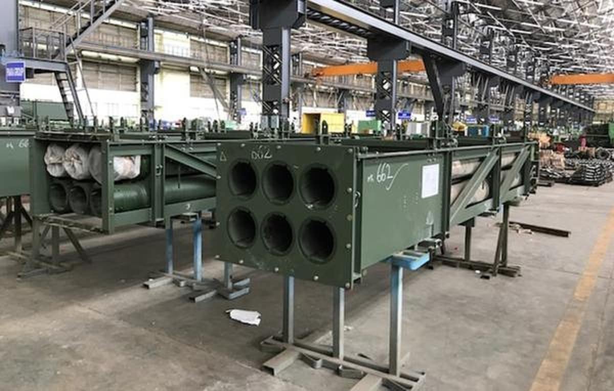 The launcher tubes on smerch or the Chinese A-100 MLRS systems consist of fixed launcher tubes where only one type of rocket can be fitted. The A-100 MLRS exported to Pakistan has fixed launched tubes of 300mm Artillery calibre. The A100 artillery rocket system has 10 launch tubes for 300 mm artillery rockets (the original Smerch has 12 tubes). Chinese manufacturers claim that the A100 is not compatible with the 300 mm rockets of the Smerch. They also insist that Chinese rockets use different propellant motors and components. A standard rocket is 7.3 m long and weighs 840 kg. A variety of warheads are available, including High Explosive Fragmentation (HE-FRAG), fuel-air explosive, and cargo warheads. It is claimed that the A100 MLRS has a maximum range of 120 km, versus 90 km of improved Russian Smerch. Newer improved Chinese MLRS are being seen in a pod frame configuration. Pinaka Configuration in Detail.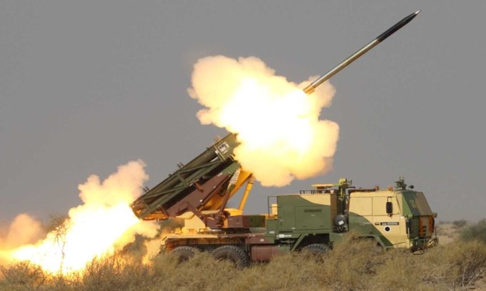 It's not just about the rockets and launchers pod, the Pinaka is a whole system that works in sync to deliver unmatched firepower to its user. The entire system consists of the Mobile Launcher which is fitted with rocket pods, A loader cum replenishment vehicle, a normal replenishment vehicle(with no crane). A mobile command post, DIGICORA MET Radar. The entire system is integrated with ACCCS Shakti system of Indian Army that provides theatre command and control to Indian Army commanders. Launcher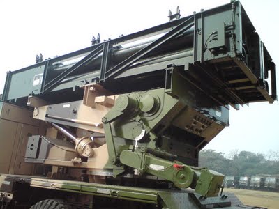 The launcher is a 2 axis revolving servo driven assembly that positions the rockets at a set azimuth and elevation. In Pinaka the launcher is integrated with an 8X8 military vehicle procured from Tatra. The launcher also has an onboard Automatic Gun Alignment and Positioning System (AGAPS) to provide land navigation and orientation capability. The function of laying is done automatically with four hydraulic legs. If the laying gets disturbed due to shocks from recoil, the system automatically stops firing sequence and commences it back after relaying. After laying an onboard software based level correction ensures accuracy. The functions of laying, levelling fuze setting, firing mode setting is performed by an onboard computer. In case of failure of automatic modes there is mode for manual or battery powered launcher levelling, laying, battery fuze setting, programming rocket data and firing. 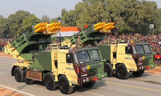 At it's best capacity all 12 rockets can be fired within 44 seconds. The entire operation of coming in laying the launcher, firing and scooting out can be performed in less than 3 minutes. The launcher itself does not need servicing upto 5 missions and is operated by a four member crew. The mobile launcher and a ring laser gyroscope based inertial navigation system for land navigation. The gyroscopes also assist the servo drive mechanism that positions the rockets for firing. The combined power from vehicles power pack and an onboard generator is used as primary power supply for operations of the launcher. Replenishment Facilities LCRV and RV.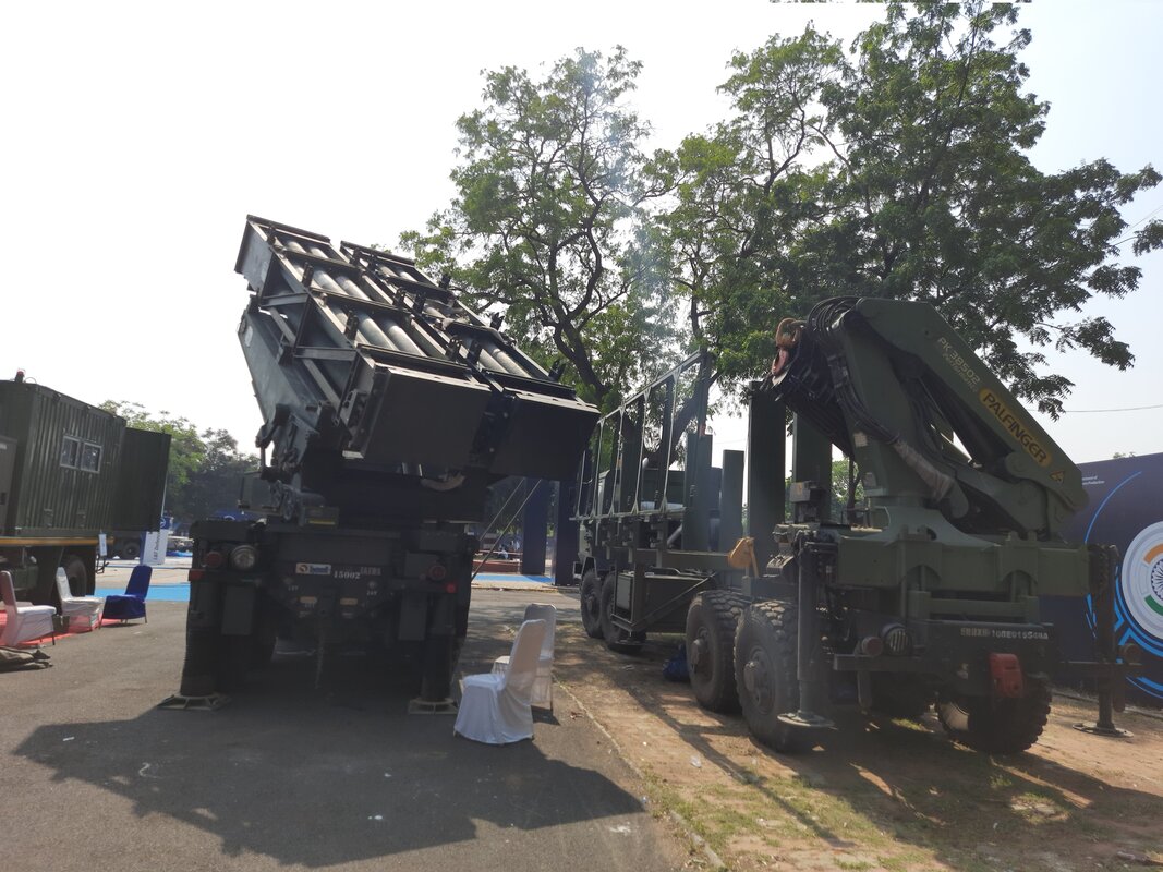 Pinaka Loader Cumbria Replenishment Vehicle and Pinaka Launcher at DefExpo 2022 Once having run out of rockets the launcher can be quickly reused. To facilitate this the replenishment vehicles come into play. These vehicles were developed in association with VRDE. The Loader Cum Replenishment Vehicle LCRV has a crane of lifting capacity of 3.5 tons and carries four pods. The replenishment vehicle RV doesn't have a crane but has collapsible side walkways to let the crew move around while handling the rocket pods. Once the launcher runs out of rockets the expended pods are quickly replaced with new ones. This allows quick rearming and resuming an attack. 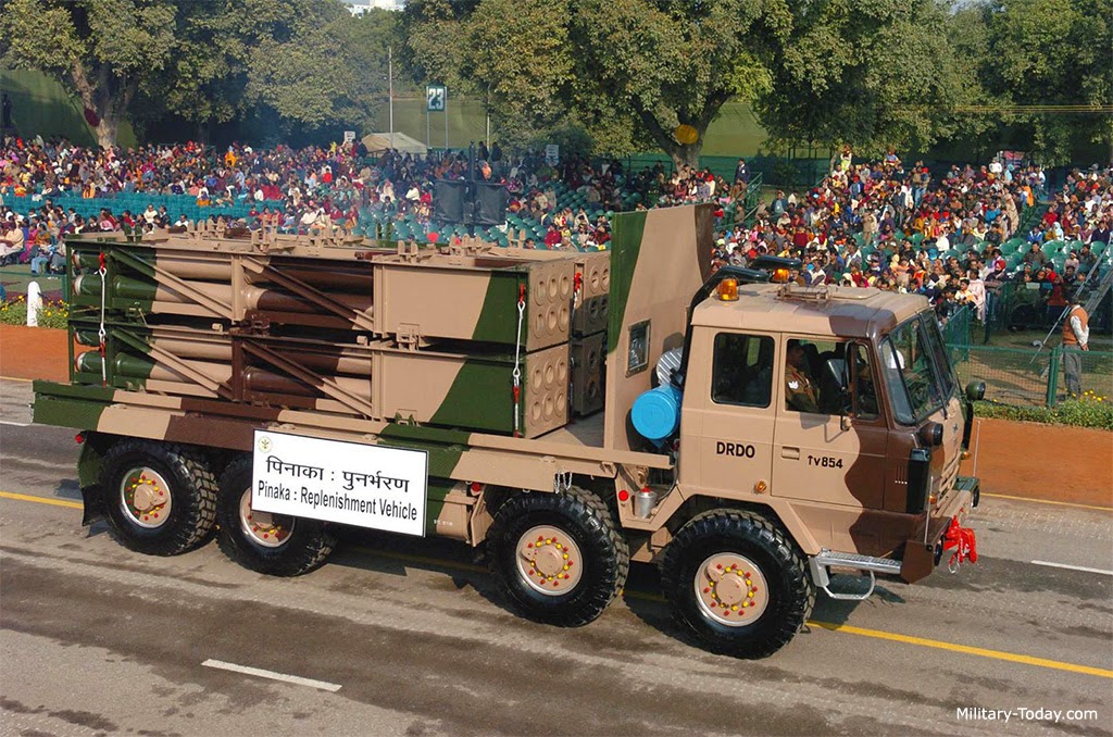  DIGICORA MET radar.The Metrological radar obtained from DIGICORA has been adopted for the Pinaka system. This type of radar is called radiosonde. They are battery powered sensors mounted on a balloon and released in atmosphere to collect meteorological data like wind speed and wind direction. This data is used by battery command post to formulate the right trajectory for firing of rockets. The wind speed and direction would affect the flight of rocket veering it away from target. The data from MET radar helps in planning. Battery Command Post.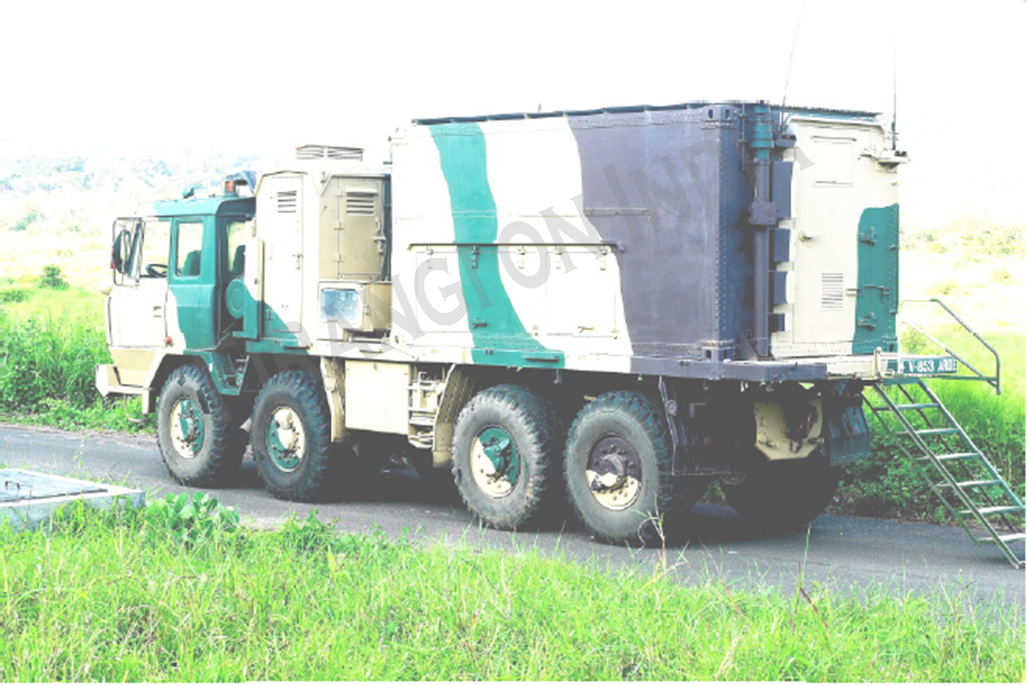 One battery consists of six launchers. All these are controlled and commanded by the BCP. The BCP directs the launchers into to set trajectory and fire when necessary. The BCP has tactical computers communication equipment and are air conditioned. They are equipped with NBC air ventilation system and have shielding against EMI/EMC (electromagnetic interference/electromagnetic compatibility). Through the tactical computers and comms, the commanders sitting in BCP are in constant communication with higher commanders via the Shakti ACCCS network. The main functions are collection of information about target location, live position of friendly launchers. Collection of meteorological data, computation of trajectory and planning for firing sequence. Most important function is to command and control the launchers. Rocket Development Overview.Indian Army have a total requirement of 22 regiments and 1.89 lakh rockets. The Pinaka mk1 soon after completion of development in the 90s saw action during Operation Vijay of Kargil War. Even DRDO personnel went on warfront. The mk1 demonstrated a maximum range of around 40km and has been successfully inducted into forces. Continuing the iterative development Pinaka mk2 has been developed having improved range and being comparable with launchers and other ground systems already in place. The mk2 uses improved propulsion systems, six flat fins instead of four curved WAF fins and other contemporary technologies. The mk2 development also gave birth to mk1 enhanced which has a range of 45+ kms. This development is also under progress. The critical project goals achieved by this development program are developing an industrial ecosystem comprising of different DRDO labs, OFB and private companies. Also other achieved critical goals are as follows. 1 Family of Warheads for rockets. 2 Different types of Fuzes and detonators. 3 Technology and understanding behind Wrap Around Fins. 4 The submunition bomblets and their small fuzes. 5 Ignition systems for solid propellants. 6 High energy materials as solid propellants. 7 Softwares for trajectory computation. THE PINAKA IS A WORLD CLASS ROCKET SYSTEM DEVELOPED INDIGENOUSLY BY THE PAINSTAKING, CONSISTENT EFFORTS TAKEN BY SCIENTISTS AND PRIVATE INDUSTRY PARTNERS. 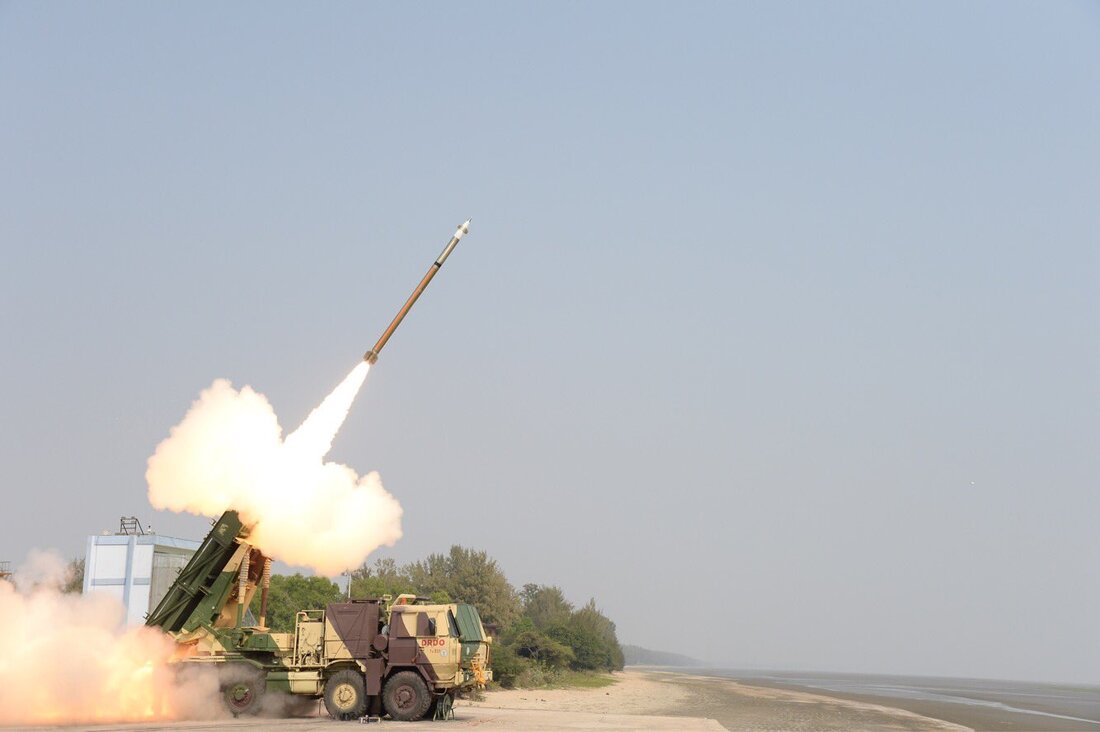 Pinaka Mk2 The Pinaka rockets provide an unmatched conventional superiority to our forces in a tactical battle and is fully compatible with the Cold Start Doctrine. The strike formations required to move fast would have a guaranteed support for massive attack on the enemy within a short time. As well as the holding formations of army will be able to pin down large invading forces. During the sub conventional warfare like situation between India and Pakistan, the development of such a long range artillery provides the capability to strike deep to the terrorist launch pads operated in POK. In the mountainous warfare, where Artillery plays a vital role, Pinaka provides a shoot and Scoot capability guaranteeing large damages to invading columns. This amazing system developed by DRDO is an example of how indegeneous systems empower a country to achieve self reliance. The economic benefits of which are also massive as just 55 crore rupees of investment has returned almost 61,000 crore rupees. Plus it developed private vendors and created jobs. We wish Pinaka system to be aggressively pitched for exports. WE CREATE TOP CLASS CONTENT SPARING TIME FROM OUR PERSONAL LIVES. IT IS DIFFICULT TO MAKE SUCH CONTENT AS IT INVOLVES A LOT OF BACKGROUND RESEARCH.WE WILL CONTINUE TO DO SO FOR A FORSEEABLE FUTURE AS WE ARE PLANNING TO BUY OUR OWN WEBSITE DOMAIN. IT IS ABSOLUTELY IMPORTANT THAT WE SHOULD REMAIN FINANCIALLY STRONG TO BRING SUCH CONTENT. WE REQUEST READERS TO CONTRIBUTE SOME AMOUNT FOR OUR CAUSE. Introduction A UGV is essentially an evolution in combat technology that will have a large scale impact on the way future wars will be planned, fought and won. The deployment of UGVs will not only protect trained human lives in dangerous battlefield situations but also a variety of potential UGV applications for military operations can significantly increase mission performance, enhance combat effectiveness, and ensure personnel safety. The deployment of UGVs enable standoff operations and thereby reduce or remove operator risks in highly stressful and dangerous environments, such as active minefields and areas of explosives or Chemical, Biological, Radiological and Nuclear (CBRN) hazards. The diverse operational roles a UGV can perform include active combat roles, operations in dangerous or contaminated environments (mine fields and nuclear-biological– chemical-contaminated areas), disposal of UneXploded Ordnances (UXO) and Improvised Explosive Devices (IEDs), utility and logistic support roles, etc. Mission Unmanned Tracked (MUNTRA). CVRDE took up the prestigious UGV project ‘Conversion of BMP-II into Tele-operated and Autonomous Vehicle’ during 2007. The project was subsequently named as Mission UNmanned TRAcked (project “MUNTRA”). The objective of this project was to convert three BMPII classes of tracked amphibious vehicles into teleoperated/autonomous UGV platforms and to implement payloads for unmanned missions of surveillance, NBC reconnaissance and mine detection/marking missions. The system configuration consists of three UGVs (one for each of the payload missions) and one base vehicle. The developed UGVs are named as MUNTRA-S for unmanned surveillance missions, MUNTRA-N for unmanned NBC reconnaissance missions and MUNTRA-M for unmanned mine detection/marking missions. The base vehicle is MUNTRA-B, from which the UGVs are teleoperated through wireless communication links. Salient Features of the MUNTRA-B (Base Vehicle)
CVRDE has developed a range of stateof- the-art UGV technologies, systems and integration/evaluation methodologies during this project. The intended terrain of deployment of the UGVs is the hot and dry desert terrains of the north western regions of country. 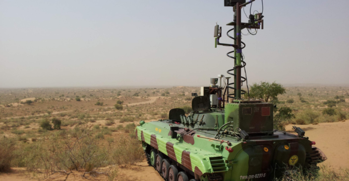 Base Vehicle The base vehicle (MUNTRA-B) is a BMP-II platform to match the cross country performance of the UGVs. All the three UGVs (but currently one at a time) are tele-operated from the base vehicle. The operation is planned in such a way that both the base vehicle and the UGV are driven manually to the point of deployment. Then the control of UGV is switched to tele-operated mode from the base vehicle and thereafter it is teleoperated by the operator from the base vehicle. Throughout the mission, the base vehicle is static and the UGV is mobile. To ensure that the communication link is always maintained, the antennae are mounted on a GPS based tracking system in the base vehicle. 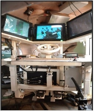 Major Systems of MUNTRA UGV Each of the three MUNTRA UGVs has a DBW and tele-operation system to enable mobility through teleoperation. In addition, each of the three UGVs has a specific payload to carry out its intended mission. There are seven major systems in the MUNTRA UGVs. CVRDE has designed, developed, integrated and validated these seven major modules on the BMPII vehicles to convert them into self contained UGV platforms. Drive-by-Wire This core technology involves conversion of the manually operated driver’s controls (acceleration, brake, steering, etc), into electronically operated controls, thus enabling teleoperation of the vehicle. This technology is primarily the design of EMAs for each of the driver’s controls, their integration within the driver/engine compartment of the BMP vehicle and the control through software. After the initial verification trials in CVRDE, this new technology was validated by tele-operating the MUNTRA-S during the summer field trials at Mahajan Field Firing Ranges (MFFR), Rajasthan during May 2012, where the temperature touched 52 0C. Subsequently, the system was also integrated on two more BMP vehicles (MUNTRA-N and MUNTRA-M), which were also validated through field trials. Subsequently, the DBW systems in all the three UGVs were operated successfully during various summer/ winter trials. This is the first trial evaluated DBW system developed in India for the BMP-II class of tracked vehicles. 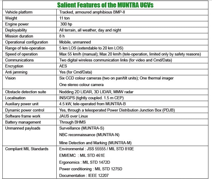 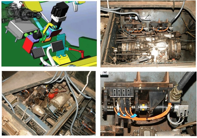 Tele-operation Module The tele-operation system (along with DBW system) forms the core of UGV. During the project, various stateof- the-art technologies and sub-systems were designed and developed for the teleoperation system. The tele-operation system was integrated in the BMP vehicles and was successfully validated during numerous summer/winter trials at MFFR during the period 2012-2014. This is the first time in India that a UGV of this class was tele-operated under actual field conditions. 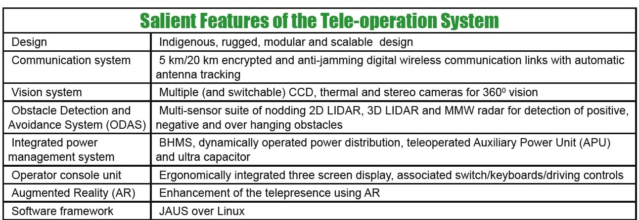 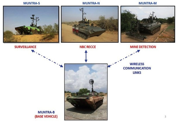 Surveillance Payload This payload is integrated on the MUNTRA-S UGV and is meant to carry out unmanned surveillance operations. Ground and sea targets upto 18 km can be detected and tracked. MUNTRA-S is configured for unmanned surveillance missions using a suite of surveillance sensors, consisting of Battlefield Surveillance Radar-Short Range (BFSRSR) radar and an integrated electrooptics (with CCD/TI/LRF) mounted on a retractable carbon composite lightweight mast. Using this payload, a single operator can carry out the surveillance upto a range of 18 km under all weather, day/ night conditions. The full range of the collected surveillance data is transmitted to the base vehicle, where it is displayed for the information of the operator. The innovative feature in the design is the automatic slaving of the electro-optics to the radar for the visual confirmation of the target detected by the radar. The surveillance payload was successfully validated during the field trials conducted at MFFR during the summer of 2012. 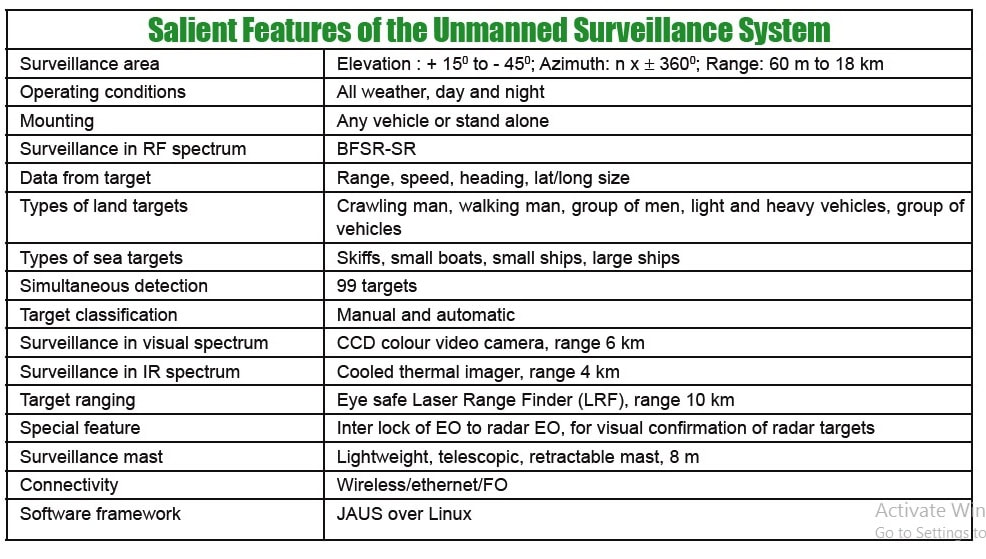 NBC Reconnaissance Payload This payload is implemented on the MUNTRA-N UGV, which is meant for unmanned NBC reconnaissance operations. The NBC reconnaissance payload is mounted on the MUNTRA-N and is teleoperated from the base vehicle MUNTRA-B, and is intended to carry out unmanned reconnaissance missions in NBC contaminated areas. The primary NBC detectors are the nuclear radiation detector, a Chemical Warfare Agent/Toxic Industrial Chemical (CWA/TIC) detector and a Biological Agent (BA) detector. The full range of the collected NBC data is transmitted to the base vehicle MUNTRA-B, where it is displayed for the information of the operator. The MUNTRA-N was successfully trial evaluated at MFFR during summer of 2014. 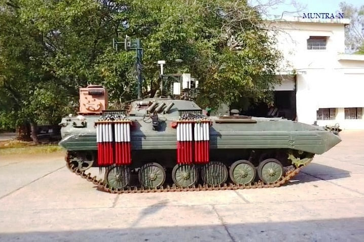 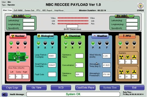 Mine Detection Payload This payload is implemented on the MUNTRA-M UGV, which is meant for unmanned mine detection and marking missions. The primary mine detection sensor is the Ground Penetrating Radar (GPR) and the confirmation is given by the Vapor Detection System (VDS). The GPR is mounted on two six-axis parallel manipulator arms and the VDS is carried by a five-axis manipulator arm. Once the mine is detected by the GPR, the vehicle is automatically stopped. Then, the mine will be confirmed by the deployment of the VDS. Once the mine is confirmed, its location will be automatically marked by using paint spray as well as will be marked in the GUI in the base vehicle. The mine detection system can be tele-operated from the base vehicle MUNTRA-B or manually operated from MUNTRA-M. The deployment of the MUNTRA-M is also shown. The processed GPR data is transmitted to the base vehicle for the visualisation of the mine by the base vehicle operator. This data includes information about the depth, size and position of the detected mine-like object. The development of a real time algorithm for detecting the buried mines within 200 ms while the vehicle is on the move and stopping the UGV on detection is a significant achievement by CVRDE. The real time algorithm was developed by combining many detection techniques like clutter removal, parabola estimation, feature extraction and classification, etc. 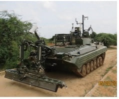 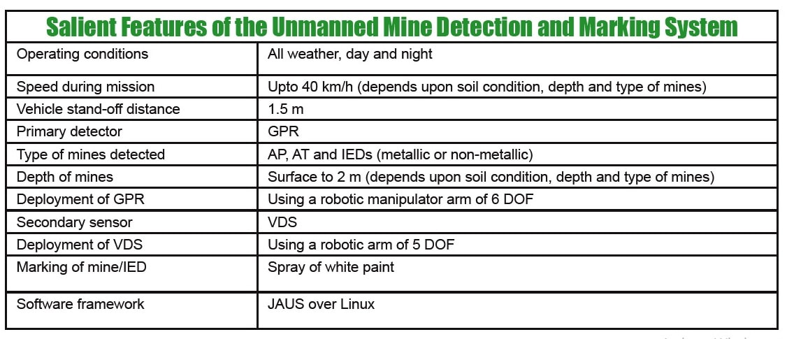 Autonomous Navigation Module Autonomous Navigation System (ANS) is a cutting-edge technology for the autonomous navigation of vehicles. This module provides a limited autonomous navigation capability to the UGV. Based on a given sequence of GPS way points, the vehicle automatically navigates from the start location to the destination location by following all the defined GPS way points in between. It also has the capability to detect and avoid obstacles in the path. The crux of the ANS is the path planning algorithms, efficiency and execution speed. Thus two types of path planning are used in ANS: the global path planning and the local path planning. The global path planning involves the generation of alternate paths between the GPS way points. The optimum path is then selected based on a cost map, which is essentially the degree of difficulty of each path. The local path planning is used to avoid obstacles in the path and get the UGV back to the planned path. The detection of the obstacles is done using a sensor suite on the vehicle, consisting of 2D and 3D LIDARs. The LIDARs give the location of the obstacles with respect to the vehicle. Based on the size of the obstacle and the safe region defined around each obstacle, an alternate path is planned by the local path planning algorithm. Once the obstacle is avoided, the vehicle moves back into the pre-planned path given by the global path planner. For the ANS, the software was developed by CAIR and the hardware was developed by CVRDE. The vehicle navigation commands (steering, accelerator, brake, etc.) was generated by the ANS software and forwarded to the DBW controller. The DBW controller finally controls the vehicle driving system (steering, accelerator, brake, etc.) through a set of EMAs. The feedback from the DBW controller and from the localization sensors is used for the closed loop control of the vehicle to ensure that it follows the specified GPS way points. Various obstacle detection strategies and navigation algorithms were developed and implemented for the ANS module. Integration, testing and demonstration of the autonomous navigation system on MUNTRA-S were successfully completed in June 2014 at MFFR. 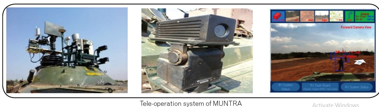 Electronically Controlled Powerpack The existing BMP-II vehicle is fitted with a 300 hp (UTD-20) powerpack with manual transmission and steering system. For this UGV project, the interface to the engine was through the EMAs attached to the vehicle driving controls (steering, accelerator, brake, etc.). This introduces latency in the response of the UGV. To overcome this latency, a direct electronic interface to the engine/transmission is necessary. Therefore, a 400 hp powerpack engine and transmission) was specially designed and developed to meet this requirementof the MUNTRA project. This Electronically Controlled Power Pack (ECPP) can be directly controlled by appropriate electronic signals, without the intervening need for an electromechanical DBW system. Along with the 400 hp powerpack (with electronically controlled engine, automatic transmission and brake system) the required auxiliaries (viz. cooling system, air filtration system, etc.) were also developed.All these systems have to be mounted within the existing engine compartment. The mobility criterion of the existing vehicle is to be retained in this upgraded system. The upgraded system is electronically interfaced by means of a Main Controller Unit (MCU) with engine control unit and transmission control unit. The systems interact with each other on a J1939 protocol wherein all control commands, system health checks, interlocks and diagnostics data are interfaced. The MCU interfaced with a telemetry system for wireless control of the powerpack. A GUI is provided for the operator to monitor and operate the system. A number of technical difficulties were overcome by CVRDE during the realisation of this powerpack. This is the first electronically controlled powerpack of this class in India. The 400 hp ECPP was integrated in a BMP-II vehicle and was extensively field validated at MFFR during November- December 2015. During the successful field validation of the 400 hp CPP, it was found the response and the handling characteristics of the vehicle were better as compared to a manually operated BMP-II vehicle. 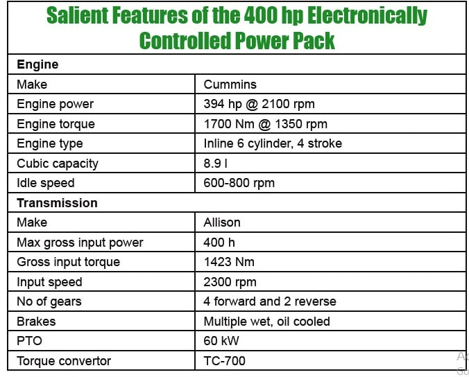 Demonstration and User Field Trials The MUNTRA-S and MUNTRA-B were demonstrated during the prestigious Defence Expo-2012 at New Delhi. Various dignitaries and other eminent visitors appreciated the concept and the implementation of UGVs. As a spinoff effort, in association with the Dte of LIC (DRDO HQ), a demonstration of the capabilities of MUNTRA-S and MUNTRA-M were given to the Central Armed Police Forces (CAPF) under the Ministry of Home Affairs (MHA) during May 2015. The requirements of the CAPF/ MHA in the domains of surveillance and mine/IED detection were discussed during the demonstration. Based on the requirements of the CAPF/MHA, an extensive six months user trials were carried out by the MHA to assess the suitability of the Unmanned Surveillance System (USS) for coastal surveillance applications. This intensive user trial was conducted by the Central Industrial Security Force (CISF) at the Chennai Port Trust (ChPT) from 01 August 2016 to 30 January 2017. During the user trial, the USS was extensively used by the CISF 24x7 for the surveillance of sea shore and sea based targets. Various targets on the sea were detected and cracked by the CISF upto a range of 18 km during this user trial. At the end of the trial, the MHA/CISF has stated that the USS is extremely useful for them and is very effective for surveillance of large areas with minimum manpower requirements. Based on the user requirements, CVRDE has also mounted the USS on a movable trolley for easy and quick deployment. Further follow-up is being taken up with the MHA through the Dte of LIC in this regard. 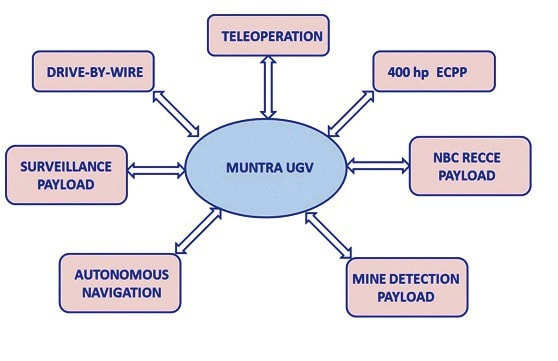 Future: Development of an Unmanned Combat Ground Vehicle The Unmanned Combat Ground Vehicle (UCGV) is an unmanned ground vehicle with a suite of remotely operated weapons (current international conventions do not permit the use of autonomous weapons, even though the technology is readily available). The deployment of UCGVs will greatly enhance the battlefield effectiveness and generate force-multiplier effects. It is projected that in the immediate future, the role of humans will be greatly reduced in the war front and the actual fighting will be done by UCGVs and similar machines. As a proactive measure, CVRDE has drawn up future plans for the design and development of a tracked UCGV in a progressive manner through three phases. The first two phases will develop a UCGV on the existing BMP-II tracked vehicles. The weapons systems shall include a Remote Controlled Weapons Station (RCWS), a soft kill Active Protection System (APS) and a medium power Directed Energy Weapon (DEW) system. A new high speed tracked vehicle platform shall be specifically developed for the new UCGV in the third phase. In addition to the RCWS with enhanced fire power, this new UCGV is expected to have a hard kill APS, high power DEW, SAMs, attitude control system and active camouflage. 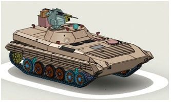 UGV Roadmap for CVRDE Though the current technologies are based on tele-operation and limited autonomy, the technologies developed by CVRDE can be extended further for the development of UGVs capable of undertaking more complex missions in dynamic and uncertain battlefield scenarios. Based on the future battlefield scenarios and the increasing pace of technological developments, it is projected that UGV technologies will move from the current tele-operated UGVs to fully autonomous networkcentric UGVs by 2050. Accordingly, the UGV developments in CVRDE will also migrate to more evolved UGVs capable of complex missions in uncertain battlefield conditions. The missions undertaken by the UGV will also shift from a passive logistics/ support role to highly active weaponised combat missions. Combat UGVs will initially have only defensive capabilities, but will rapidly evolve into a potent platform for offensive military perations deep inside the enemy territory. The future road map for UGV developments in CVRDE is also shown. Significant spinoff developments for internal security applications will also be part of the roadmap. Current systems use varying combinations of tele-operation and assisted autonomy for the systems to follow pre-defined routes, automatically detecting and avoiding obstacles along that route. Future UGV applications will require the development of more powerful technologies for autonomous navigation, starting in the near term with refinement of leader-follower technologies completely autonomous operations in unstructed terrains and harsh environmental conditions. Also, advances in machine learning is essentialto reduce the cognitive burden on operators, enhance efficiency of machinehuman interactions, and enable more advanced operations, such as manned and unmanned teaming. Other key technology focus areas include the enhancement of high-mobility and all-terrain attributes; continued development of power train and battery technologies to support increased endurance; navigation and timing technologies that do not rely on spacebased signals; secure communications under NLOS conditions; automatic target classification, tracking and engagement; and operations in swarms. As the future battles will be fought predominantly by unmanned or a by a composite collaborative teams of mannedunmanned systems, countries with technological competence in this very critical field will decide the outcome of all such future armed conflicts. Faced with potentially hostile situations both inside and outside our country ranging from a fully fledged war to low intensity conflicts, CVRDE/DRDO should rigorously pursue a long term plan for the development and deployment of UGVs to guard our borders and to make our country self-sufficient in this very critical technological domain. 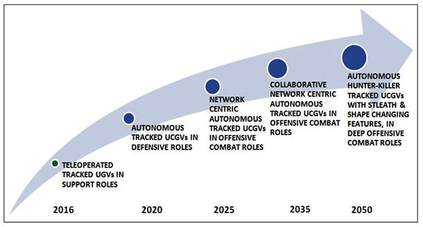 Pinaka multi barrel rocket launching (MBRL) system, named after the divine bow of Shiva, is an all-weather indirect fire free flight artillery rocket system. It delivers accurate and massive firepower at high rate over extended ranges. Pinaka was designed to replace the BM-21 Grad multiple rocket launcher systems of the Indian Army. 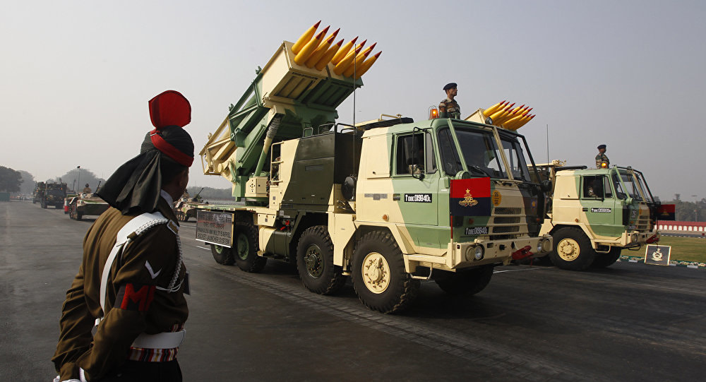 Overview The Pinaka rockets have been developed by the DRDO as battlefield multi-barrel rocket launcher to take down enemy tanks and other moving targets. The mission of this all-weather all-terrain Artillery weapon system is to deliver large volume of fire within a very short time. The complete system comprises a launch vehicle, a loader / replenishment vehicle, and a command post vehicle with a battery of six launchers. A battery of six launchers can fire a salvo of 72 rockets. The warheads can be delivered a range between 10 km to 70Km and can effectively neutralize a target area of 1000 m by 800 m. In terms of its characteristics, the system is highly mobile and can attack enemy in depth with strike and counter fire capabilities. Its awe inspiring fire power adds substantially to the defensive and offensive capabilities of the Indian Artillery. Pinaka can neutralize various types of targets, namely, POL and ammunition dumps, gun positions, wagon lines, communication centers, rocket positions, moving columns of A or B vehicles, forward helipads, surveillance radar, and assembly areas. It can be fitted with a variety of warheads ranging from blast-cum-pre-fragmented high explosives to anti tank and anti tank personnel mines. The system was to incorporate a twelve tube cluster configuration capable of firing a salvo in from six launchers. The entire operation of loading of one salvo from six launchers from the replenishment vehicle to the launcher was required to be completed within four to five minutes. Eight type of warhead for different targets effects were developed. Pinaka can fire 12 rockets at intervals of 4s.Hydraulically actuated outriggers helps to level & stabilize the vehicle during firing. Special alloys are cast for the structures to keep their weight compatible with the capacity of the vehicle. Reinforced chassis vehicle to provide a platform for mounting the armament system. The propulsion is provided by High-Energy Composite (HEC) propellants. The motor tubes made of high intensity steel are seamed with silica-phenolic materials for resisting higher flame temperatures. The optimised nozzle design ensures a very high thrust. The Army generally deploys a battery that has a total of 72 rockets. All the 72 rockets can be fired in 44 seconds, taking out an area of 1 km2. Each launcher can fire in a different direction too. The system has the flexibility to fire all the rockets in one go or only a few. This is made possible with a fire control computer. Salient Features
 Subsystems Seemingly simple the system in fact comprises of a large number of sub systems and sub sub systems. The main components are as follows
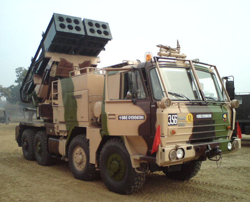 The Pinaka System vehicles are configured around indigenously built Tatra 815VVnN 8X8 chassis. Tatra chassis was selected on the basis of excellent long distance road and cross country mobility. Tetra vehicle also has the advantage of being a standard vehicle in its class being used in various roles by many arms and services of the Indian Army. The propulsion system consists of high strength motor tubes and high energy composite propellant grains specially developed to achieve high thrust and specific impulse. A modified six degree of freedom trajectory model was developed and validated over a number of flight trails. Rockets are loaded into pods making stowage, transport, loading and unloading easy. The pods are open frame structure made of special light weight high strength Aluminum alloy, holding six rockets in separate FRP launch tubes. Warheads The rockets can be fitted with wide range of warheads including pre-fragmented high explosive, anti-tank bomblet, anti-tank minelet warhead, anti-personnel mines, incendiary practice and pilot shot. The pre-fragmented warhead delivers 25% to 30% more destructive power than the conventional warhead. The HMX-based composition is used in anti-tank bomblets / minelets to achieve 150mm armour penetration. Monolithic warheads developed for Pinaka include performed fragments (PF) and incendiary types. PF warheads provide dual purpose blast cum fragmentation effects. These warheads incorporate 21000 tungsten balls, which on initiation travel at high speeds and cause lethal damage over a large area (MAE-12000M2). The design has been perfected by choice of optimum c/m ratio ensuring higher density of fragments. Incendiary warheads wit zirconium based incendiary composites spreads burning chunks over an area of 100m radius with a burning time of 3-4 min. These warheads are effective against FOL dumps and other inflammable targets. Proximity fuzes are set to height of burst of 0 m and incorporate ECM features. Controlled variable Time (CVT) fuzes with anti jamming features of pseudo random phase modulation technique are also developed. Electronic Time Fuzes with time setting range of 6 to 200 seconds in steps of 100 milliseconds have also been developed. They have multiple setting options including setting from launcher computer and FCC. These fuzes have a data retention time of two hours.  Launcher The launch system of Pinaka consists of two pods mounted side-by-side. Each pod houses six launcher tubes made of E-glass / epoxy composite materials. The pods are loaded / unloaded into the launcher vehicle by a loader crane mounted on the replenishment vehicle. The launch system can fire a salvo of 12 rockets within 40 seconds. The launcher traverses 90° left / right from the centreline and can elevate up to 55°. The launcher is capable of operating in autonomous mode, stand-alone mode, remote mode and manual mode. The fire control computer (FCC) independently controls the launcher in autonomous mode. The stand-alone mode involves entering the commands into console by the operator. The remote mode allows the operator to control the launcher from a distance of about 200m using a remote control unit. The manual mode is adapted in the event of microprocessor failure and loss of power. The vehicle can carry a payload of 12t. It is equipped with an on-board generator supplying primary power for launcher operations. Other equipment aboard the vehicle includes a microprocessor-based thyristor power unit, a joy stick controller and a manual back-up. The pinaka launcher is a mobile system with capability of laying and launching 12 rockets individually or in a programmed ripple fire mode. The system also has an onboard AGAPS automatic Gun Alignment and Positioning System to provide navigation and orientation capacity for the launcher. Some of the special features are enumerated below
Modes of operation The launcher can operate in the following modes: Autonomous mode. The launcher is fully controlled by a fire control computer (FCC). The microprocessor on the launcher automatically executes the commands received from the FCC, giving the operator the status of the system on displays and indicators. Stand-alone mode: In this mode, the launcher is not linked to the FCC operator, and the operator at the console enters all the commands for laying of the launcher system and selection of firing parameters. Remote mode: In this mode, a remote control unit carried outside the cabin up to a distance of about 200 m can be used to control the launcher system, the launcher site and to unload the fired rocket pods from the launcher. Manual mode: All launcher operations including laying of the system and firing are manually controlled. This mode is envisaged in the situations where the microprocessor fails or where there is no power to activate the microprocessor-based operator’s console. AGAPS The Automatic Gun Alignment and Positioning System have been integrated with Pinaka launcher. The AGAPS uses a ring laser gyro coupled with accelerometers toform a strap down inertial sensor. This system has 1 Milli-Radian accuracy in orientation and achives high precision fire, fast reaction time and improved for safety. The system is coupled with the GPS and provides hybrid land navigation for the launcher. The crew does not need any external help to manage its navigation in the field and to engage targets. It thus obviates the need for pre-survey and requirements of separate survey team. It incorporates function to manage mission preparation through way points and itinerary for convenient navigation. Fire Control System The pinaka FCS consists of Command Post, Fire Control Computer and Digicora Met Radar. It is linked with other control elements and forward observers through voice/data communications. 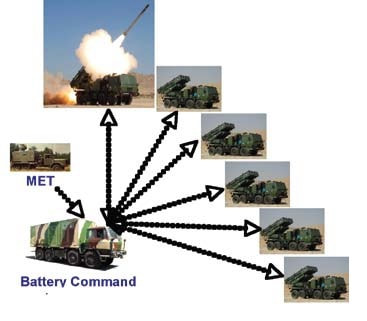 Loader cum Replenishment vehicle The ammunition supply chain consists of 6 LCR vehicles carries two pods each and three Rvs carrying four pods each. This chain can supply four salvos of to each Launcher. The LCR vehicle is used for transfer of rockets pods to the launcher. The pods are handled with the help of an onboard hydraulic crane of 3.5 ton capacity. A 3 member crew mans the LCR vehicle. In addition there are 3 replenishment vehicles per battery carrying four pods each . High operational mobility, flexibility and accuracy are the major characteristics which gave Pinaka MBRL system an edge in modern artillery warfare. 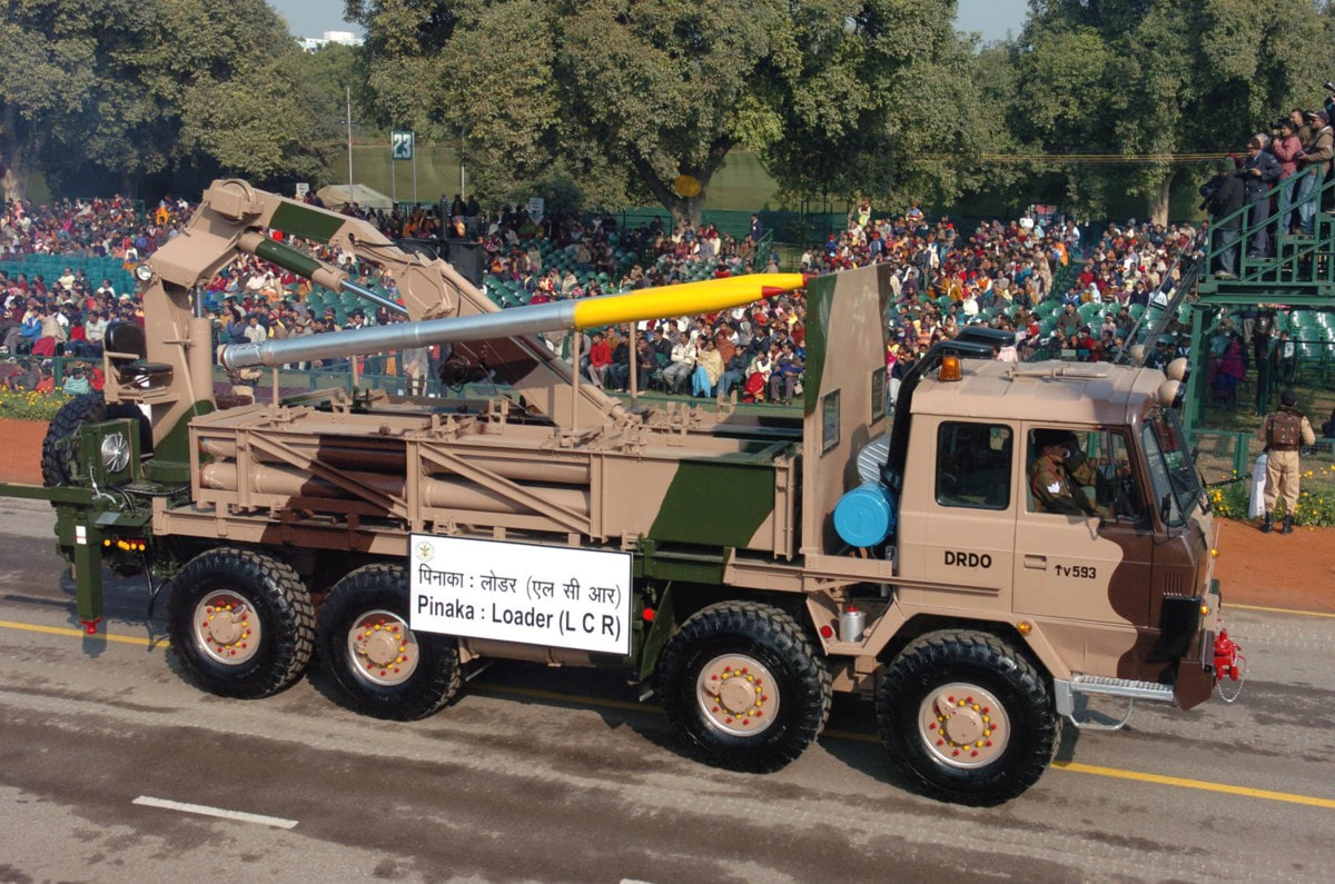 Pinaka Mk-II Pinaka Rocket Mark-II, which has evolved from Pinaka Mark-I, is equipped with navigation, guidance and control kit, and is converted to a guided Pinaka. The conversion into improved guided Pinaka rockets has helped in enhancing the range and accuracy of Pinaka. The earlier range was 40 km, but now it is more than 70 km. This conversion has led to enhancement of its strike range and considerably improved its accuracy. The accuracy of the missile is estimated to be between 60m-80m at all ranges. In tests Pinaka achieved a CEP of just 8m for 65Km. The rocket was fired from a multi-barrel rocket launcher (MBRL). The rocket launcher can fire 12 rockets with 1.2 tonne of high explosives within 44 seconds and destroy a target area of 4 sq km at a time. The quick reaction time and high rate of fire of the system gives an edge to the Army during a low-intensity conflict situation. The weapons capability to incorporate several types of warheads makes it deadly for the enemy as it can even destroy their solid structures and bunkers. The rocket incorporates a high performance solid rocket propulsion system and advanced stabiliser system with six flat fin configurations. The Pinaka Mk-II uses in-service warheads and fuses and existing ground systems with minor modifications in the Launcher, Loader-Cum-Replenishment (LCR) vehicle, Replenishment Vehicle (RV) and Battery Command Post. Pinaka can also convert into guided rockets for delivering nuclear warheads at small ranges, if needs. After successful development and incorporation of command guidance system in Pinaka Mark-II, the system shall be able to replace Russian SMERCH Multi-Barrel Rocket Launcher (MBRL) It was successfully tested at the Chandipur Test Range in January 2013, and on 20 December 2013. On 20–23 May 2016, four rounds of the Pinaka Mk-II were successfully fired from the test range of Proof and Experimental Establishment (PXE) at Chandipur-on-sea for testing a new guidance system. On 12 January 2017 and 24 January 2017, two successful tests were conducted with range of 65 km and 75 km respectively from Launch Complex-III, Integrated Test Range, Chandipur. The Pinaka is in the process of further improvement. Israel Military Industries teamed up with DRDO to implement its Trajectory Correction System (TCS) on the Pinaka, for further improvement of its CEP. This has been trialled and has shown excellent results. The rockets can also be guided by GPS to improve their accuracy. A wraparound microstrip antenna has been developed by DRDO for this system. 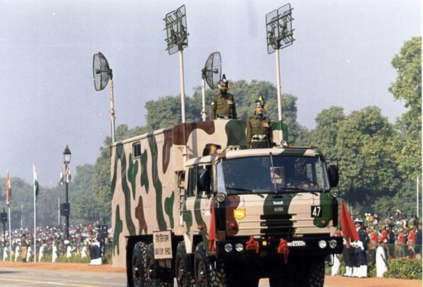 Pinaka Mark 3 Mark-III variant will have a range of 120kms and can carry 250kg payload which is likely to make its debut by 2020. Next Generation Pinaka will be replacing Russian Supplied SMERCH Multi-Barrel Rocket Launcher (MBRL) which has a range of 90kms. Deployment The Pinaka was tested in the Kargil conflict and proved its effectiveness. Since then it has been inducted into the Indian Army and series production has been ordered. The Pinaka MBRL is stated to be cheaper than other systems. It costs ₹2.3 crore (US$350,000) per system compared to the M270 which costs ₹ ₹19.5 crore (US$3.0 million). The Pinaka will be operated in conjunction with the Indian Army's Firefinder radars and indigenously developed BEL Weapon Locating Radar of which 28 are on order. The Indian Army is networking all its artillery units together with the DRDO's Artillery Command & Control System (ACCS), which acts as a force multiplier. The ACCS is now in series production. The Pinaka units will also be able to make use of the Indian Army's SATA (Surveillance & Target Acquisition) Units which have been improved substantially throughout the late 1990s, with the induction of the Searcher-1, Searcher-2 and IAI Heron UAVs into the Indian Army, as well as the purchase of a large number of both Israeli made and Indian made Battle Field Surveillance radars. These have also been coupled with purchases of the Israeli LORROS (Long Range Observation and Sighting System) which is a combination of FLIR/CCD system for long range day/night surveillance.Presently, 2 regiments of Pinaka have now been inducted by the Army, an additional 2 are on order and the MoD has cleared a RFP for 6 more regiments. The Indian Army has plans to operate a total of 10 regiments by 2022 and increase this to 22 within the next 10 years as the older Grad MLRS regiments are retired 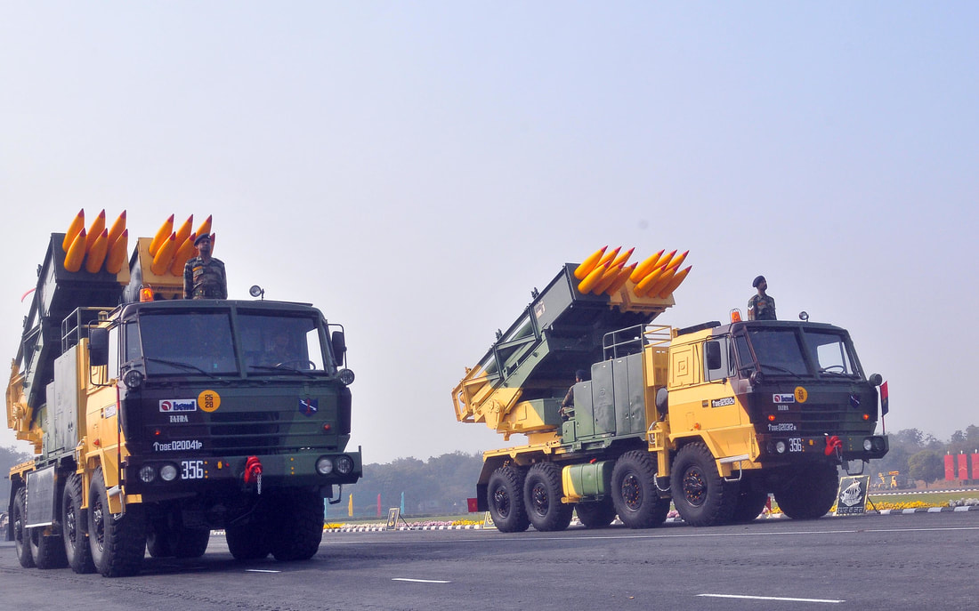 Production The production target is for 5000 rockets per annum. To set up infrastructure for meeting production requirement, it is planned to reduce manual work to optimal minimum by application of automation in most of the operations like pick and place, movements of heavy parts from one station to another station during assembly operations and hold the parts in position while aligning and assembling to assist skilled manpower to work effortlessly and increase output. Production Overview. 1. Pinaka rocket is received at O F Chanda in two parts i.e Warhead and Propulsion Unit. 2. Empty Propulsion unit received are marked for assembled position before dismantled, for filling and final assembly. 3. Empty warheads are filled with explosives and assembly. 4. Finally Warhead is integrated with Propulsion unit and rocket made ready. 5. Complete assembled rockets are loaded into Pod, which is specifically designed to hold 6 rockets. 6. The pods loaded with rockets are temporarily stored for dispatch. Finally moved to main storage at magazine or dispatched to army depots on trucks. Reference DRDO Army technology Wikipedia 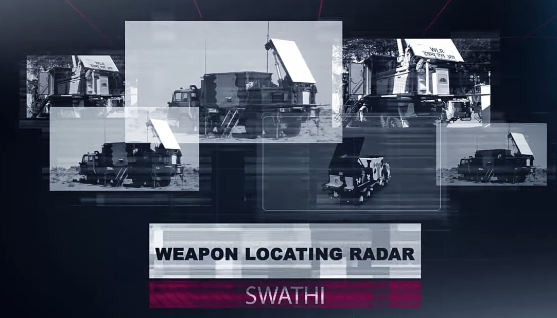 While movement of the troops in rugged terrain towards the enemy is in progress. The biggest hurdle they could face is, enemy's artillery fire. We have faced such a hurdle during Kargil Conflict in 1999. The initial level of troop movement was mediocre because as per intelligence only some terrorists had crossed the borders and occupied unmanned posts, but it later came to know that they were wolves in sheep's clothing and were actually a light infantry along with special forces supported by artillery.  An initial advance by Indians to capture Tiger hills was heavily suppressed by enemy's artillery fire. Days passed without any knowledge about exactly where does this artillery come from. While the Pakistani forces were equipped with American AN/TPQ-36 Firefinder radars, India only had British Cymbeline mortar detecting radars, which were not suitable.Weapon locating radars are the most convenient and robust tools to spot enemy artillery gun positions based on the trajectory followed by their projectiles and tracked by WLRs. WLRs usually can also track mortar shells and unguided rockets. Some WLRs also have limited missile tracking and Air Defence capabilities. WLRs also has a secondary job of tracking and directing friendly artillery fire. The radar can provide trajectory correction to friendly artillery to pinpoint their fire towards enemy precisely.  Introduction :~Swathi is a coherent, C Band, passive electronically scanned phased array radar. Intended to be used as weapon locating radar, it has been designed to automatically detect and track incoming artillery rounds, mortar and rockets, and locate the hostile launchers. As a secondary function it can observe friendly artillery shell’s trajectory to see where they fall short and provide fire corrections to counter the enemy fire. The biggest technological challenge in the design of Swathi lied in achieving high probability of location for all calibers of projectiles having very low radar cross section (RCS) both for high and low angle fire. This was addressed by a complex array design and stringent algorithms which makes the radar capable enough to work effectively even under severe clutter and high density fire environment.  System Platform :~During tests of the Akash missile at Chandipur, engineers noticed the Rajendra radar was able to detect and track artillery shells being test fired at a nearby range.Based on this observation, LRDE scientists were able to adapt the Rajendra Array into the WLR. Swathi system is configured into two vehicles named as, radar vehicle and power source-cum-BITE vehicle. The radar vehicle contains electronic and antenna shelter. The power source-cum-BITE vehicle contains two diesel generator sets and radar target simulator. The WLR is designed for quick deployment and decamp, and can be ready for action within 30 minutes. In case of any incoming threats, the radar can be quickly moved out of the threat area. The Radar is designed to operate in harsh environments ranging from -20 to +55°C, in hot and humid conditions, and can be safely stored from -40 to +70°C. It can operate at high altitudes up to 16,000 feet (4,900 m). Shock & vibration performance and resistance to EMI/EMC are according to international military standards. 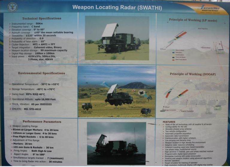 An adaptive algorithm based on modified version of the Runge-Kutta method and incorporation of constant false alarm rate (CFAR) techniques aid in the accuracy of target detection. An operator can select the suitable CFAR technique for maximizing accuracy of track/information. The data is processed on the state-of-the-art programmable digital signal processor using modified extended Kalman filters (one with size six states and another with seven states). Moving target indication (MTI) aids to improve the clutter rejection performance of the radar. Target information is presented as a high resolution multi-mode colour display on the ruggedised power PCs in real time and can be overlaid on a digital map. The WLR can store a large size digital map for display purposes. System Functioning :~The array is first set at a mean bearing for reference. It can electronically scan up to +/-45° from its mean bearing. It can also be slewed to 135° on both sides to achieve a total 360° coverage within 30 seconds to quickly change the scanning sector in response to potential threats. At a stable position it can scan a target in one quadrant that means encompassing a 90° sector. The radar works in C Band The Coherent TWT based transmitter of the WLR emits 40 kW of power. Tracking of the target is done with monopulse signals with Pulse compression, which improves the radar's LPI. Pulse compression is a signal processing technique commonly used by radar, sonar and echography to increase the range resolution as well as the signal to noise ratio.  This is achieved by modulating the transmitted pulse and then correlating the received signal with the transmitted pulse. One commonly used technique is phase coding the pulse is divided in N number of time slots of duration T/N for which the phase at the origin is chosen according to a pre-established convention. For instance, it is possible to not change the phase for some time slots π (which comes down to just leaving the signal as it is, in those slots) and de-phase the signal in the other slots by (which is equivalent of changing the sign of the signal). The precise way of choosing the sequence of { 0,π } phases is done according to a technique known as Barker codes. It is possible to code the sequence on more than two phases (polyphase coding). As with a linear chirp, pulse compression is achieved through intercorrelation. The radar data can also be displayed on any screen far away from radar so that operators stay protected in case of the radar itself is attacked. Many radars can be linked together with each other to operate in tandem to provide more information with enhanced accuracy which boosts overall situational awareness of decision makers.The data can be automatically transmitted to a command centre and can be communicated with higher echelons. Up to 99 weapon locations can be tracked and stored at any time. As soon as the target is detected, system automatically acquires and classifies the threat and initiates a track sequence, while continuing to search for new targets. The incoming round's trajectory is tracked, and a computer program analyses the track data and then extrapolates the round's point of origin. This calculated point of origin is then reported to the radar operator, thus allowing friendly artillery to direct counter-battery fire towards the enemy artillery.  Algorithms for trajectory computations use environmental factors, along with trajectory and track data, for estimating both launch and impact points to the desired accuracy. The fence concept of beam positioning, and grazing the radar air space, makes it impregnable for hostile projectiles without detection. The computed launch point can be reported by the radar operator to the friendly artillery to direct counter-battery fire towards enemy artillery. Tracking of the target is achieved with mono-pulse signals and the in built pulse compression features improve the radar’s low probability of interception (LPI). Its processors perform real-time signal processing on the acquired data. Up to 7 targets can be tracked simultaneously. The radar can track rounds fired at both low and high angles, and at all aspect angles - from behind or towards the radar, or at an oblique angle to the array. Swathi features adaptive radar resource scheduling to increase efficiency and reliability. 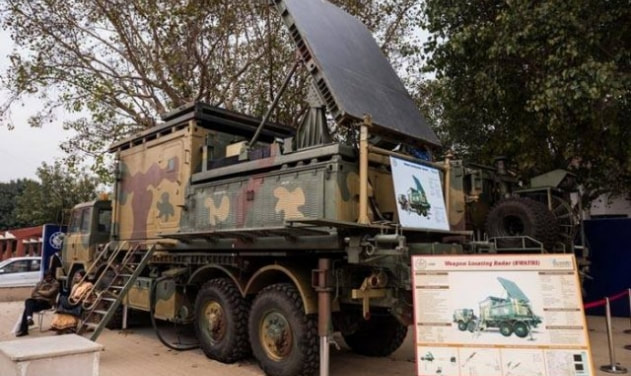 Deployment in Service :~An indigenous WLR was deemed necessary and found it's requirement a long time ago but a parallel attempt to purchase a foreign radar prevented full scale sanction of funds. Then lethargic attitude caused delays and coated very dearly during Kargil Conflict. As due to the Nuclear tests India was banned from receiving any such system or foreign help DRDO was simply helpless. They still somehow managed to resurrect WLR from Rajendra radar of Akash missile system and presented the first prototype at AeroIndia 2003. After which work was done in steadfast pace user trials began in 2005 and by mid-2006 it was declared ready. The radar was displayed in 2007 on Rajpath on the occasion of Republic Day parade.  DRDO officially handed over the WLR Swathi to Indian Army on 2nd March, 2017 for service induction.Currently, the radar is using passive array but efforts are going on to upgrade it with active array to enhance performance and reliability. As well as a long range enhanced version and a compact version for mountainous regions is in pipeline. 28 radars are on order it is believed that around 40 to 50 are needed. 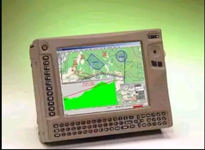 The Network :~The Swathi WLR is networked with artillery units around via a secure network called Shakti ACCCS. All artillery units are inter-connected with each other and act against enemy force as whole. This combinedly beefs up the level of situational awareness which is very important for commanders to quickly take decisions.The ACCCS Artillery Combat Command & Control System is a network of military grade tactical computers that automates and facilitates decision support for all the operational aspects of artillery functions from the Corps down to a Battery-level in a networked environment. ACCCES is a major subsystem of C31 systems being fielded in the Indian Army. The role is to automate all the operational functions of Artillery from the Corps Fire Control Center (FCC) down to the Battery Command Post with Gun Display Units at the individual gun level. In September 2003 a contract of 300 million USD was awarded to BEL to develop the ACCCS. 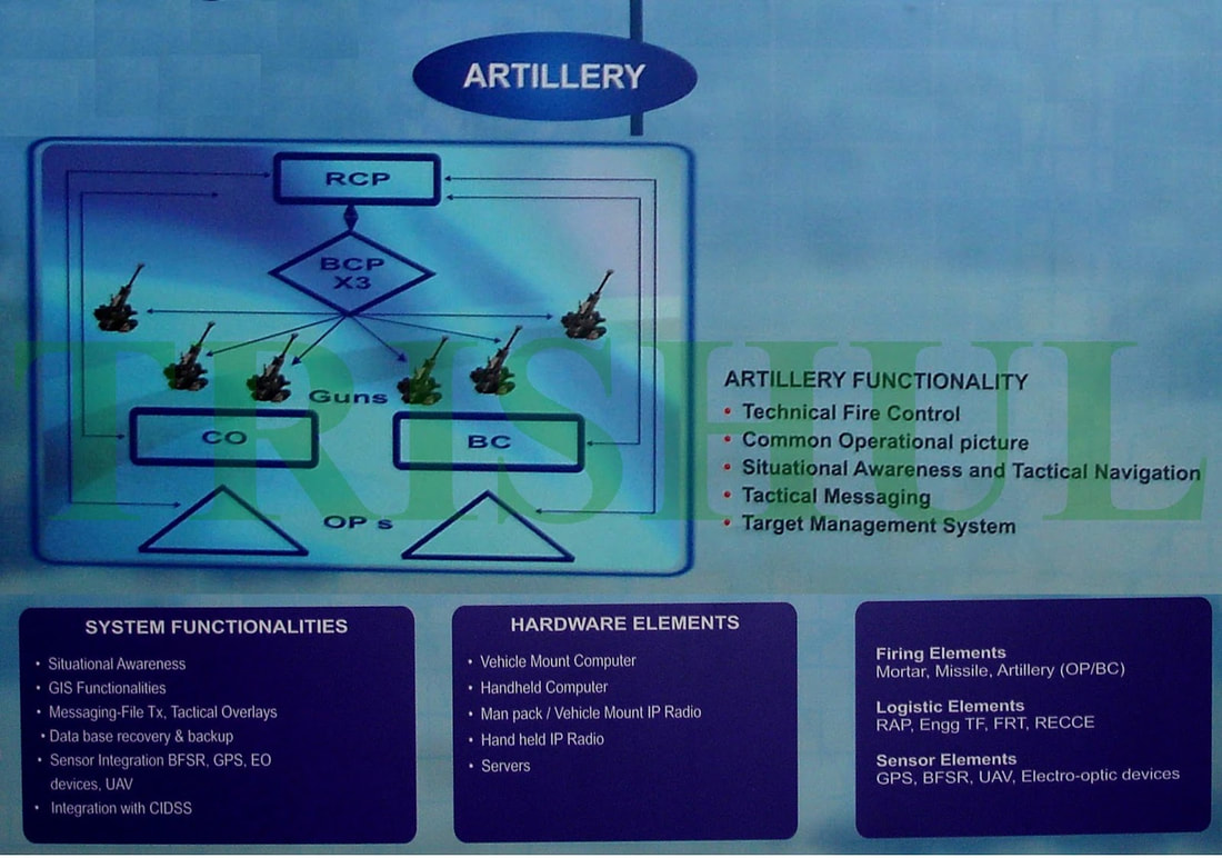 ACCCS is the artillery component of the IA’s TAC-C3I grid. Shakti’s three main electronic devices are the enhanced tactical computer, gun display unit and the hand-held computer. With these, five critical functions are performed, including ‘Technical Fire Control’ for trajectory computations, and ‘Tactical Fire Control’ involving the processing of fire-assault requests and ammunition usage/supply management. It also ensures ‘Deployment Management’ for field howitzers and forward observation/fire direction posts for defensive and offensive operations, ‘Operational Logistics’ for assisting in the timely provisioning of ammunition and logistics support, and ‘Fire Planning’ to facilitate the production of interleaved fire-assault plans, tasking tables and automatic generation of gun engagement programmes. 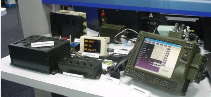 Counter Tactics against Weapon Locating Radars :~Usually WLRs are counterd by employing electronic warfare. They are either jammed or spoofed with false targets. But Swathi has been tested under high electronic clutter and high density fire environment. 4 WLRs were deployed on a live mission on border and tested against Pakistani batteries, when Swathi directed counter fire and this happened repeatedly. The Artillery fire from Pakistan got reduced. 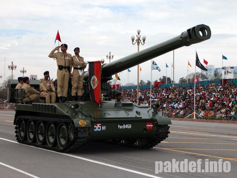 At mountainous regions deployment of artillery is a difficult job especially using the surrounding to camouflage it. Pakistan operates American M198 , M114 155mm towed artillery, M115 203mm towed and Chinese Type-59I and D-30 130 and 122 mm towed artillery respectively. Towed artillery can be fast deployed and quickly repositioned as Shoot and Scoot is the best tactic to counter WLR guided artillery. The ranges of these howitzers are between 20 to 28 kms while the detection range of Swathi against artillery shells is said to be nearly 30 kms. It won't be difficult for Indians to seek and destroy them before repositioning and their usage isn't a big deal. Then come the Self Propelled Howitzers which Pakistan has nearly 300+ like American M110A2 203 mm having maximum range of 25 kms. M109A2 and with range 18 kms and M109A5 with 22 kms maximum range both being 155mm Howitzers category. Now SPHs can swiftly run away after firing and these ones in Pakistani arsenal would be a headache. If Indian Army somehow could detect them at the earliest then they could launch counter fire probably that's why work has been initiated for an AESA radar that can instantly detect firing locations. SPHs are usually not deployed at mountainous regions. India needs to replace its current artillery guns quickly. Good news is India’s two big companies Tata and Kalyani both have developed their own variants of a 155mm artillery which under tests are breaking each other's world records. We just as always hope that Indian Army gets top class artillery as soon as possible. As well as L&T’s K-9 Vajra soon sees induction and deployment.  General Performance :~Weapon Locating Range - 81mm Mortars - 2 to 20 km 105mm Howitzers - 2 to 30 km Unguided Rockets - 2 to 40 km Adjustment of Fire Range Mortars - 20km 155mm Guns and Rockets - 30km Firing Angles - Both High and Low. Aspect Angles - 0° to 180°. Simultaneous Target Track - 7. Time taken for deployment - 30 minutes Time taken for slewing - 135° in 30 seconds. Probability of Detection - 0.9 Image Sources :~ Click on Respective Images Info Sources :~ http://bel-india.com/Products.aspx?MId=13&LId=1&link=69 http://www.bharat-rakshak.com/media/AeroIndia2007/Brochures/WLR.jpg.html DRDO Techfocus April 2013. http://www.drishtiias.com/upsc-exam-gs-resources-Swati-Weapon-Locating-Radar-WLR-system https://en.m.wikipedia.org/wiki/Equipment_of_the_Pakistan_Army https://en.m.wikipedia.org/wiki/Equipment_of_the_Indian_Army https://en.m.wikipedia.org/wiki/Swathi_Weapon_Locating_Radar WE CREATE TOP CLASS CONTENT SPARING TIME FROM OUR PERSONAL LIVES. IT IS DIFFICULT TO MAKE SUCH CONTENT AS IT INVOLVES A LOT OF BACKGROUND RESEARCH.WE WILL CONTINUE TO DO SO FOR A FORSEEABLE FUTURE AS WE ARE PLANNING TO BUY OUR OWN WEBSITE DOMAIN. IT IS ABSOLUTELY IMPORTANT THAT WE SHOULD REMAIN FINANCIALLY STRONG TO BRING SUCH CONTENT. WE REQUEST READERS TO CONTRIBUTE SOME AMOUNT FOR OUR CAUSE.  While movement of the troops in rugged terrain towards the enemy is in progress. The biggest hurdle they could face is, enemy's artillery fire. We have faced such a hurdle during Kargil Conflict in 1999. The initial level of troop movement was mediocre because as per intelligence only some terrorists had crossed the borders and occupied unmanned posts, but it later came to know that they were wolves in sheep's clothing and were actually a light infantry along with special forces supported by artillery. Pakistani forces were equipped with American AN/TPQ-36 Firefinder radars, India only had British Cymbeline mortar detecting radars, which were not suitable To Read Full Article Click Here.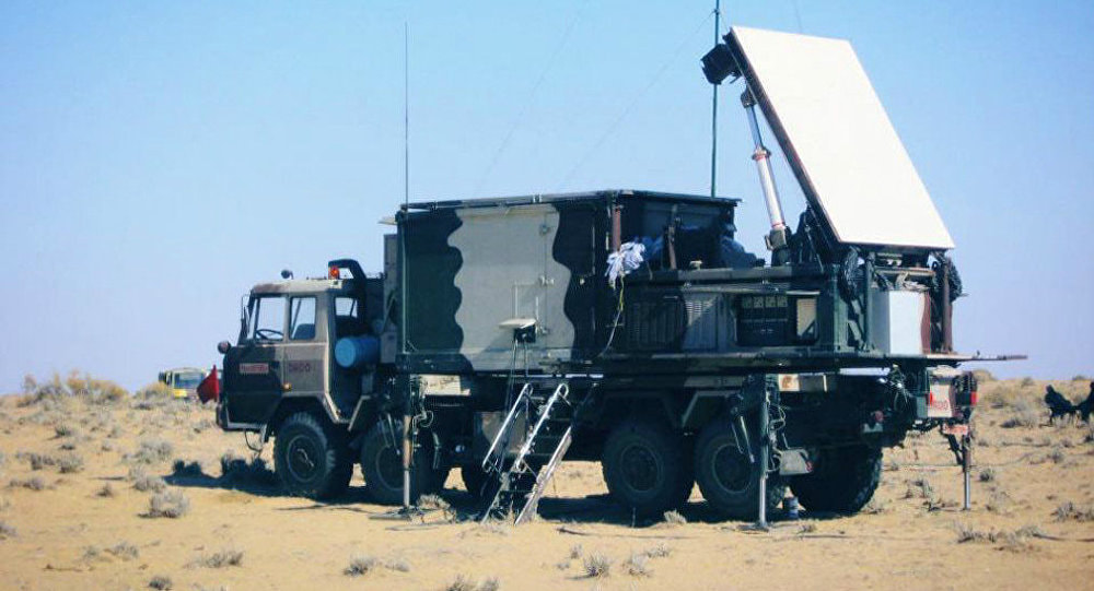 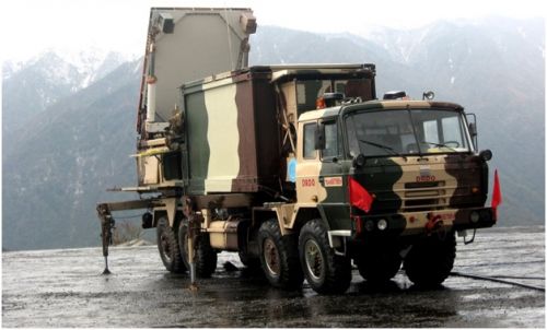 An Amazing video of Swathi Weapon Locating Radar. 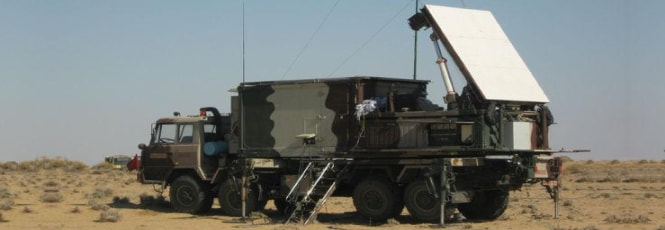 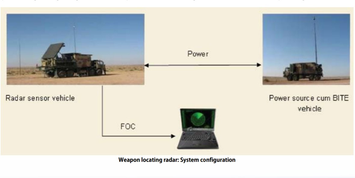 Source : Techfocus April 2013  DRDO Scientist explains how Swathi WLR works. 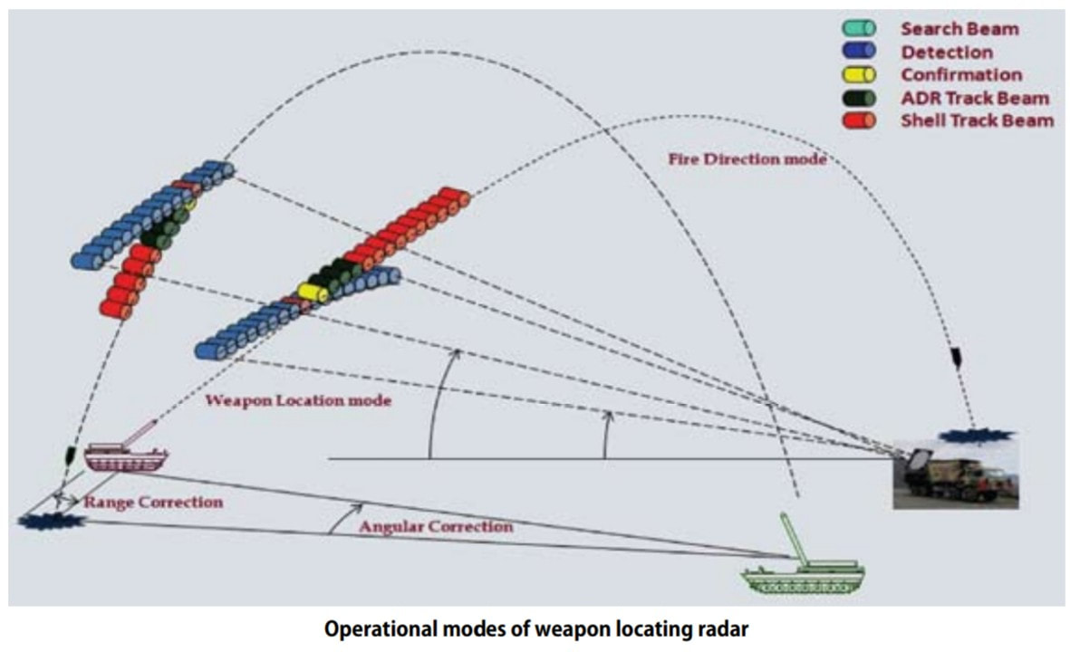 source : Techfocus April 2013   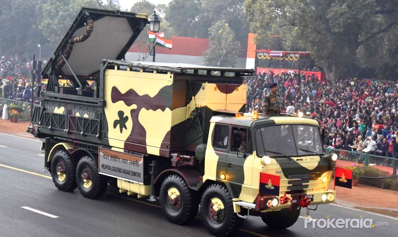 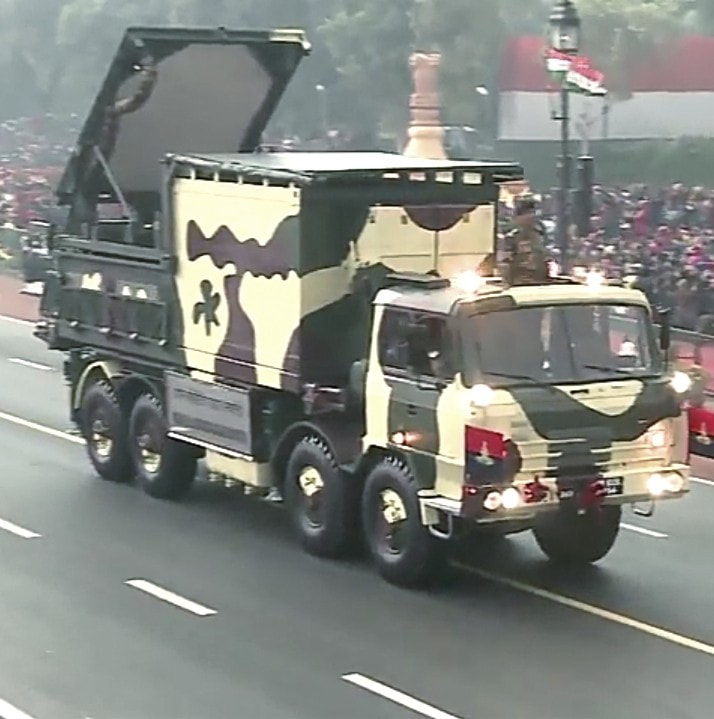  M110 Self Propelled 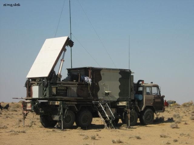 Image Sources :~ Click on Respective Images
Info Sources :~ http://bel-india.com/Products.aspx?MId=13&LId=1&link=69 http://www.bharat-rakshak.com/media/AeroIndia2007/Brochures/WLR.jpg.html DRDO Techfocus April 2013. http://www.drishtiias.com/upsc-exam-gs-resources-Swati-Weapon-Locating-Radar-WLR-system https://en.m.wikipedia.org/wiki/Equipment_of_the_Pakistan_Army https://en.m.wikipedia.org/wiki/Equipment_of_the_Indian_Army https://en.m.wikipedia.org/wiki/Swathi_Weapon_Locating_Radar Generation Next Main Battle Tank (GNMBT) 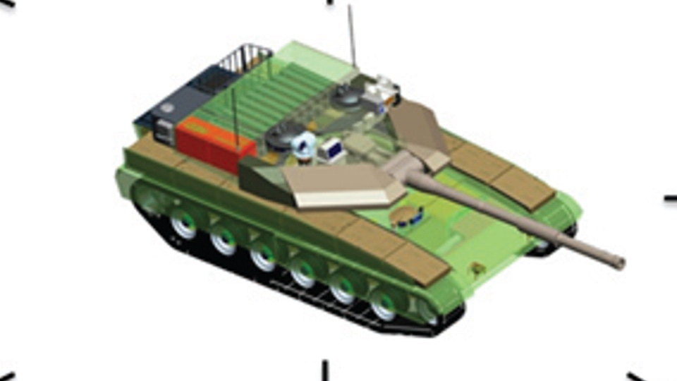 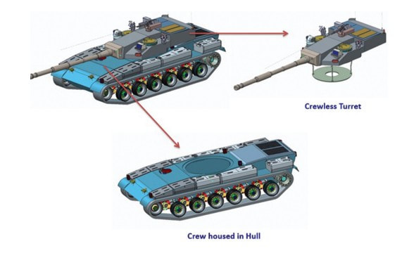 We all have seen that Indians take a long time to plan. They develop one of the best plans but many times when the plan is executed the produced outcome is already nearly outdated. A big threat is looming around as Chinese are claiming to be making next generation tanks in greater numbers whereease Pakistan is nearing Ukraine and is in process of acquiring T-84 Oplot M tanks which are considered one of the best tanks in the world but not mass produced due to economic issues of Ukraine. Considering the future threat and combat scenarios the GNMBT design faces the difficult choice of being either an EVOLUTION or a REVOLUTION. For the designing purpose certain crucial parameters should be set based upon the definition of the configuration. Certain key parameters like weight, crew, armament system, survivability, operating range, transportability, tactical mobility, trafficability, system modularity, theatre operation and ISTAR ( Intelligence - Surveillance - Target Acquisition & Reconnaissance ) have been considered. Based upon that the study fields both design considerations. Finally after evaluation the study observes that if the design of GNMBT would be a REVOLUTION then it would not just offer greater capabilities but also would be ideal for adapting it into a Universal Combat Platform. 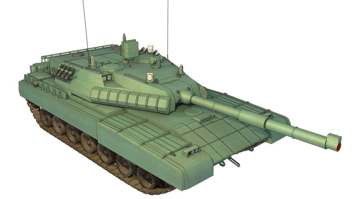 The Main Battle Tank is backbone of Mechanised Forces of an Army. The design of MBTs had been based on the philosophy which is called IRON TRIANGLE. The three sides of this philosophical triangle are firepower, mobility and protection. This philosophy had been long followed until when the proxy wars played by Militant Organisations came. It most largely happened in Soviet Afghan war and US wars post 9/11. Now the future combat scenarios involve a much greater challenge and the proxies which are more correctly called as Non State Actors also form a part of these challenges. If the GNMBT is to be considered an EVOLUTION then it would be a piece of upgraded technologies. An upgrade of what the previous MBTs used to be, just offering better of a capability than what it was previously. But if the GNMBT is thought to be a REVOLUTION then it would be a completely new previously unseen system which is Optimised considering various requirements based on and judged by set parameters. The technical advantages of Evolutionary approach aren't available in the current literature of Tank Making and it forms the main part of DRDO’s recently published paper on an internal study. 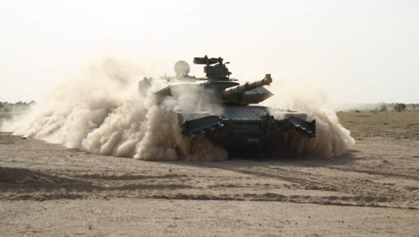 ( above and below pic Arjun MBT mk 2 an example of Evolutionary approach ) 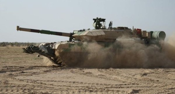 ~ Future Threat Scenario.The future threats if visualised, show us a need of an MBT with robust active and passive protection, Detection Systems, firepower as well as other necessary systems. Some of the key futuristic threats are newly seen. Man Portable Rocket Launchers, Anti Tank Missiles of new generation mounted atop Armoured High Mobility Vehicles and also from an Attack Helicopter. The high velocity precision munitions dropped by enemy fixed wing fighter aircraft, Satellite bases monitoring by enemy, The Drone warfare by the enemy. All the visualised threats are shown here in the diagram below. 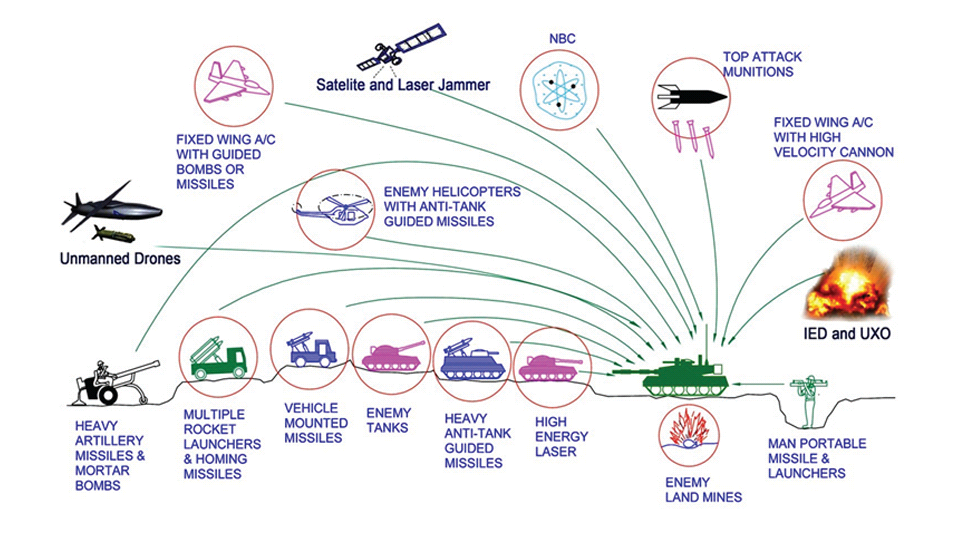 ALL THE SET PARAMETERS MENTIONED BEFORE, THEIR RELEVANCE, VARIATION, ADVANTAGES, LIMITAIONS, ETC., HAVE BEEN DISCUSSED IN DETAIL BY THE DRDO PAPER. ~ CrewWhile talking about a Next Generation tank a sure thought of making an Unmanned MBT strikes the mind. While considering current level of advancement a Man in the machine is necessary to take decisions. So how many men should we put??? One, Two, Three, Four??. It is clear that we need one Man to drive the GNMBT and one to engage the enemy. If such a two man system is visualised as shown in the diagram one limitation we face is that the man responsible for engaging the enemy is overloaded with tasks. Here in the diagram below this man has been shown at the position of a loader. So he has to load a projectile, find the targets judge their threat level, classify them then take aim and shoot. This is quite lengthy. Modern tanks feature an automatic target acquisition system which is a software that takes inputs from detection systems and classify them and set them ready to be targeted. But as a counter measure the enemy employs various modern camouflage techniques that can cheat these softwares as seen during the tests of T-14 Armata. Therefore in Armata the crew can optionally take target acquisition and prioritisation in its hands. Battespaces are filled with unexpected surprises and as a concern I am saying, It may happen that a new makeshift camouflage is innovated and is employed to cheat automated systems. Hence a man is always needed to do these assements. That man is the Tank Commander who directs the Gunner to simply take aim and shoot. 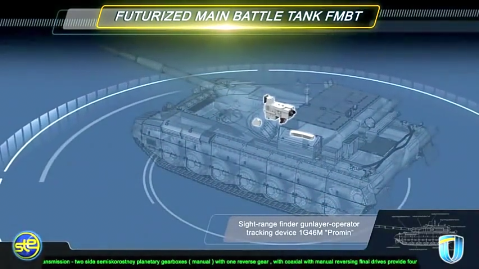 ( a concept of FMBT of Ukroboronprom of Ukraine ) Whether their should be a Man as a loader or an Autoloader is a different debate. This debate has been in process for a long time. It takes into account mechanical problems related to autoloader and vulnerability to human life when their is human loader. During such debates a clear point was stressed that since the Autoloader is housed inside the turret and if the turret is breached by a Sabot round then all the ammunition stored in autoloader would blow up bringing catastrophic destruction to the tank. Considering this various tank designers have come up with the idea of placing the crew in a capsule covered by thick armour from all sides. This would protect the life of crew even in the case of a catastrophic destruction. Such a thing can be seen applied on T-14 Armata of Russia. The DRDO study considers parameters such as internal volume, weight, crew comfort, ergonomics, endurance, redundancy and reaction time while determining number of crew. It observes that the two crew manned turret option reduces amount of protection thus reducing amount of weight but it increases reaction time, negatively affects crew endurance and increases the work load thus affecting the combat effectiveness. 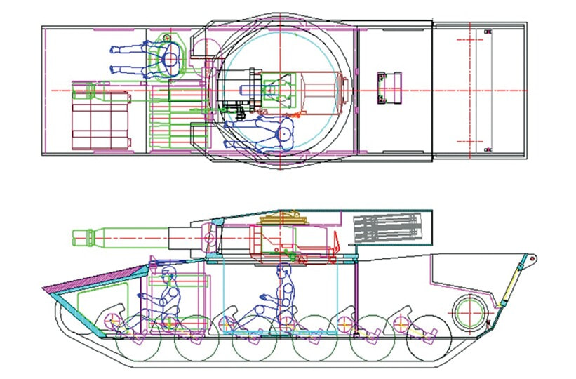 Many people are incorrectly reporting the above two crew manned turret configuration as ‘one of the preliminary designs’ but actually it has been just given as an example in DRDO’s paper describing it as a bad idea as explained above. ~WeightWeight of an MBT is taken into account considering it as fully equipped and battle ready. All the systems mounted and all the weapons loaded in the store plus the crew sitting inside already. The study takes into account that a general consideration of weight of an MBT at global levels falls in the range of some 40 to 45 tonnes. If the GNMBT is perceived as an Evolution then adjustments and optimisations of weight would come after making considerations about Lethality > Armament > Crew > Systems > Armour > Dimension Constraints. But while we are anticipating the GNMBT as an evolution the weight is the very first consideration and other things like Dimensions , Armour, Crew , Systems, Armament, etc., would be optimised according to these weight restrictions. This has been explained in the study paper by a flow chart 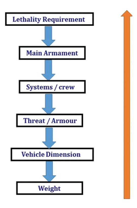 Here The Top to Bottom approach is taken into account while we make an Evolution wherease While making a Revolution we have to go by a Bottom to Top approach. DESIGNING THE GNMBT BY THE REVOLUTIONARY APPROACH IS VERY CHALLEGING BECAUSE OF THE WEIGHT LIMITS WHICH EXPECT THE PLATFORM TO BE A MODULAR ONE AND TO BE USED FOR MULTIPLE MISSIONS. ~ ArmamentNow of course the main function of GNMBT is to destroy the enemy by hurling a projectile towards it. While deciding what should be the projectile delivery mechanism certain parameters like calibre, muzzle velocity, rate of fire, power consumption, accuracy, weight, dimensions, etc, are needed that evaluate the firing mechanism and pronounces it suitable for the desired firepower. This portion of the paper is most interesting. The effect of Armament System on a Tank is given shown below in a flow chart. It seems to have taken the Arjun MBT into account. 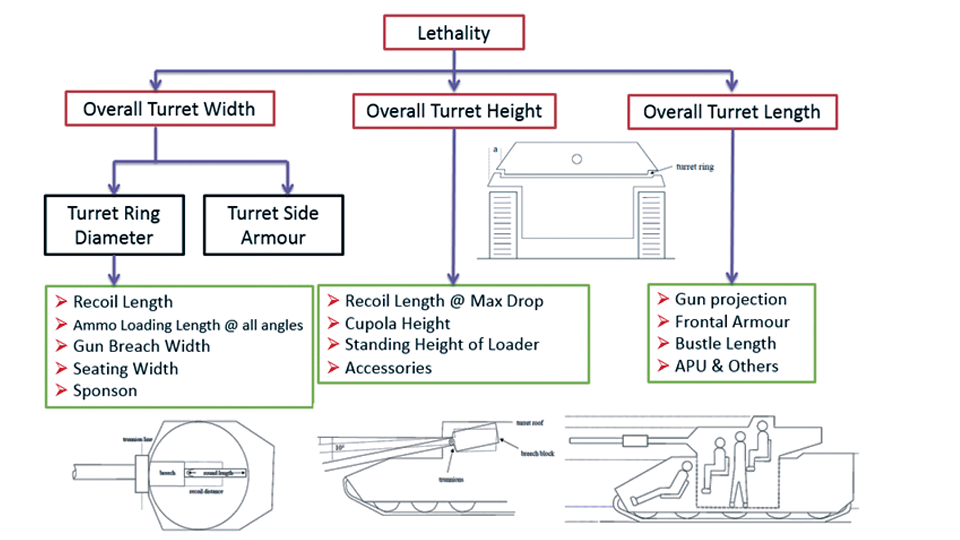 It can be clearly deduced that the characteristics of a gun would affect the configuration of turret and would then affect the hull thus affecting the design of an entire MBT. The paper states that as the recoil length increases with higher caliber, the adoption of certain technologies such as concentric or adaptive recoil along with ammunition of lesser length leads to decreased turret width. Also, it is to be noted that as the variety in ammunition increases due to mission, the dimensions need to be same to achieve uniformity in configuration. At the end it is concluded that by the having an autoloader by shifting the tunnion pivot a little bit lower helps decrease the height of an MBT thus increasing its tactical survivability. The inclination towards usage of an autoloader is also supported by some considerations discussed in the paragraph above. The DRDO has done studies related to options of gun systems. These gun systems are classified into conventional and non conventional gun systems. Let's see them. 1 Liquid Propellant Gun :- Here the liquid propellant is injected into the chamber during the combustion or prior to it. The system has earlier been evaluated in Germany and US. The trials were done for various calibre guns. 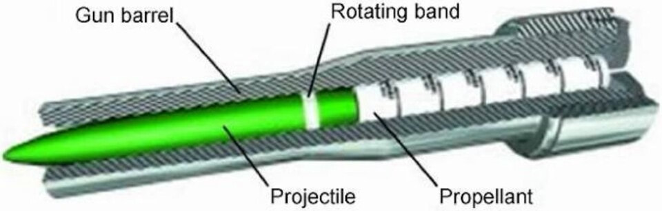 2 Electro Thermal Gun :- In this type of gun a propellant having low molecular weight is used. The propellant is converted into plasma by charging it with the help of a high voltage electrode. This system was also extensively evaluated for many different calibres. During these trials, it was observed that breech pressures could be sustained for the entire ballistic cycle with greater projectile energy for the same gun tube as used by a conventional system. 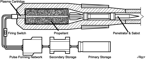 3 Electro Magnetic Gun ( Railgun) :- Here the the projectile is accelerated due to the Lorentz force generated between two electromagnetic rails. BAE hypervelocity gun program for US Navy where a projectile delivered 32 MJ of energy recently at Mach 7.4 with a range greater than 50 km is the most successful EM gun program.  Various parameters used of evaluation and the evaluated results of various guns have been tabulated in DRDO's paper which are shown below. 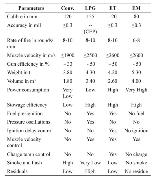 It is clear that in terms of lethality and efficiency compared to conventional armament systems the three guns mentioned above are superior and also offer lower smoke and flash in addition to ignition delay, muzzle velocity and charge temperature control. But just look at the data of power consumption, volume, weight are quite impractical if the constraints of weights, mobility and transportation are considered. So the conventional gun system still seems to be more suitable. Actually we have two options as of now. Either go ahead with the conventional gun system or wait till further developments help reduce weight and volume of the nonconventional ones. ~ ProtectionThe protection of modern tank is based on the philosophy called ‘Survivability Onion’ . A diagram can be seen below that nicely explains the layers of protection around a tank. 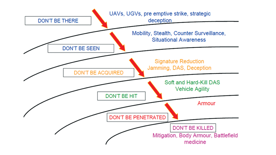 The above image specifies that initially a Tank should be designed that it shouldn't be available as a target to those remotely operated Unmanned Ground Vehicles and Drones. Later as tier 2 it should have ‘stealth’ capability to substantial levels to avoid any detection by enemy's surveillance systems. But at the same time MBT should be able to detect and have awareness about it's adversaries around. Then as tier 3 even if the enemy detects and tries to target the MBT, it must be able to use some deception techniques like jamming the signal of enemy radar or releasing smoke clouds to prevent being laser targeted. After this as tier 4 if the enemy successfully launches a projectile towards the MBT, The MBT must have a soft kill or hard kill measure. That means it must be able to repel the projectile fired at it or should be able to launch a counter projectile to stop the fired projectile in mid air. If all these 4 tiers of protection fails,Then Tier 5 involves ‘Armour’ various types of armours must ensure that the projectile fired at MBT should not penetrate inside the body. Finally as Tier 6 of the Survivability Onion as described in the paper is that Crew must have some protective clothing or the entire crew be kept in an armoured capsule. Since ages Armour has been a crucial component of entire protection system of a tank. It also contributes towards majority of the weight of any Tank. It also contributes to the size of tank which in technical terms described as volume. A pie chart shown below explains this. 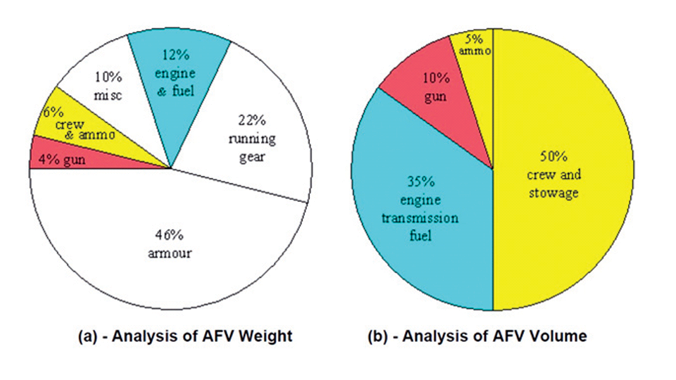 The MBT mustn't be just be anticipated for protection from the front 60° as understood by the famous Whittaker theory of directional probability of variation but considering the advanced threat scenario it must be protected 360° in horizontal plane and 180° in vertical plane as well as substantial protection under belly to prevent an IED, land mine kind of attack. As a solution a number of Active, Semi Active and Passive protection systems has been described in the survivability onion. The GNMBT if visualised as an Evolution would be based on a concept of Equivalent Protection Factor EPF. Where sloping along with add-on steel armours, composite armours with ceramic plates and explosive reactive armour (ERA) are key features. In addition, non-ferrous armours such as titanium and aluminium armour, perforated steel armour, sapphire glass armour, hybrid and non-explosive ERA and bulge armour may also be explored in non-critical areas i.e. below bustle, cover plates etc. along with EPF to achieve higher protection. For a Revolutionary GNMBT newer materials like ultra-high hardness armour steel i.e. steels with hardness greater than 600 bHN than the current 300-500 bHN shall be explored. This aids in the reduction of plate thickness used in the fabrication, thereby providing much needed weight saving. These methods of protection must be augmented with signature management techniques and active protection system otherwise would be redundant in terms of weight. The Paper suggests that, signature management techniques involve the adoption of ‘multi-spectral’ camouflage which is capable of covering the entire spectrum of sensors. In addition, thermal management in the form of exhaust configuration by sloping it upwards along with cold air blending has the potential to reduce signature. Another approach is to blend kerosene or diesel fuel to the exhaust that creates a thick smoke around the vehicle along with the existing smoke grenades capable of creating an anti-thermal anti-laser smoke. Further, certain paints such as TAN 686 are capable of reflecting radiation of upto 85 per cent and cool the exterior by 15 °C thereby reducing thermal signature. All these signature management capabilities could be achieved by obviating a system similar to BAE, UK’s Adaptive Camouflage. 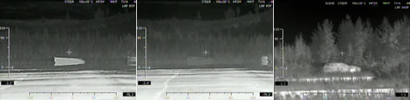 The system combines sheets of lightweight, hexagonal metallic ‘pixels’ designed to change temperature very rapidly presenting a thermal pattern that optimally blends with its surrounding. Each electrically powered pixel is individually heated or cooled using commercially available semi-conducting technology. ( pic and data from BAE Systems ) The next thing to be optimised is the Active Protection Systems. It involves constant close monitoring of an incoming projectile and launching of a counter projectile to destroy the incoming one mid air. The destruction must happen at some safe distances from the MBT so as to prevent secondary damages. The counter projectile mostly contains an explosive capable enough to destroy or disrupt an incoming projectile. This system provides protection from Anti Tank Guided Missiles, RPGs, various other Tank rounds and to some extent the APFSDS round too. The Active Protection System had always unquestionably been better than only having a combination of passive and reactive armour. While considering the threat scenario we have also considered an urban warfare, where myriad threats like IED, ATGM, Unexploded Ordnance, Blast in a nearby vicinity, Mortars, Land Mines are also to be faced. For these threats the GNMBT would also be intended to have an urban survival kit consisting of bar/cage armour, medium appliques, drag plates, tow plates, jammer, spoofer, laser dazzler and electronic countermeasures. These add on protection along with those mentioned previously would make the GNMBT capable of overcoming any kind of threat. ~ Mobility( a video of armyrecognition showing demonstration of Mobility of Arjun MBT mk2 ) General George Patton used to say that a Good Plan violently executed today is better than the Best Plan executed next week. Clearly he understood the importance of having your forces directed at right places at right times. So the terrain battle machine which matters the most must be able to manovere through the battlefield and get itself to the enemy. The decisions regarding mobility of the GNMBT would be taken considering some factors. The range is defined according to different operating speeds it is different at Max speeds and different at cruising speeds. This affects the configuration as it imposes both weight and volume based constraints. The Operational range which is decided considering the military doctrine of the maker nation as rate of fuel consumption of the available powerplants. For that the amount of fuel carried should also be optimised. First we have to see that the MBT has to be designed to roll through very impossible barriers like uneven rocky stepped surface or may involve crossing a trench. With respect to agility, it depends upon the power available at the drive sprocket (a function of gross engine output and losses due to transmission and other elements) in relation to the vehicle weight and the flexibility of the transmission, steering and suspension systems. Also, agility reflects the capability of the vehicle in the following circumstances. •Acceleration at different terrains. •Radius of turn at different speeds at various terrains. •Responsiveness of the transmission to engine loads. •Dynamic response of the hull to the transient shock loads imposed by rapid movement over rough terrain (The maximum usable speed across terrain). 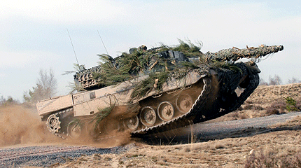 ( Krauss-Maffei Wegmann Leopard 2 main battle tank leaps in the air while demonstrating it's mobility. ) The Overall Mobility of the tank would also involve ability to roll through a varied terrain, soft terrains like porus sands, swamps, porus snow,etc as well as hard terrains like rocky surface or surface filled with gravel. The research paper nicely explains mobility of the two visualised MBTs viz. the Evolutionary and Revolutionary designs by giving a set of equations involving necesaary mechanical parameters and the placement of various forces acting at certain points on the body. After reading them I came to an opinion that understanding these diagrams and those equations need a person with some background knowledge of Mechanics. I think many of our readers may necessary not be Mechanical Engineers or Civil Engineers to understand that so I am not mentioning them here but one thing I would like to share that…. Mobility characteristic parameters depend only on vehicle specification and does not depend upon the type of soil on which it operates, whereas mobility limit parameters are designed to indicate the minimum strength of soil on which the vehicle is expected to remain mobile. Various methods have been proposed and after optimising the configuration for both the the visualised MBTs the Evolution design or the Revolution design, the one which offer superior mobility as per the above parameters be chosen. ModularityThis is quite simple but remarkable thing in context of Indians. The GNMBT must be adaptable for various battle conditions depending upon the terrain of the theatre of war. For ex. for high altitude warfare the heavy turret be replaced with a light turret (i.e. 105 instead of 120 mm) thus enabling higher mobility. The armour choices must also be available and the mix of armour needed should be reconfigurable. Indians who are experts in ‘jugaad’ ( on time adjustments ) has to take this into account. A general overview prompts us that the Revolution design would be better reconfigurable than the Evolution which simply consists of add-ons. 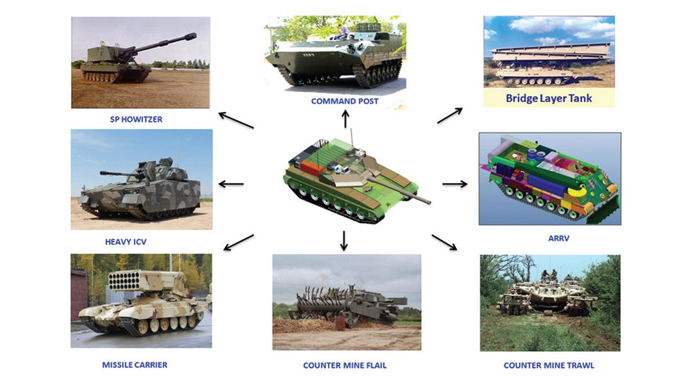 Transportation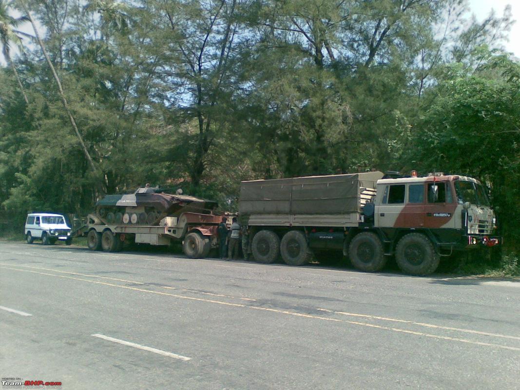 The transportability is the ability to ship an object via various transportation facilities available. Here taking logistics of the Army into account the Tanks have been transported via trucks, Railways and Cargo Planes. The volume of the Tank must then be optimised in such a way that it should be Transportable. And also it must not face any logistic problems while doing that. For self transporting the Tank the size and strength of Indian roads in various civilian and military areas should be taken into account as well as strength of civilian bridges. This prompts the designers to have some weight and size based restrictions while designing the tank. While transporting the Tank via Trailers, Railways and Cargo Planes some predefined regulations are to be followed. These regulations become the basis of design’s weight and volume restrictions. The over dimensioned consignment (ODC) which consists of three classes namely A, b and C for Indian Railways. Out of which the class A is suitably chosen as unhindered movement is ensured on all lines which results in least possible time during deployment. The diagram for ODC Indian Railway is given below. 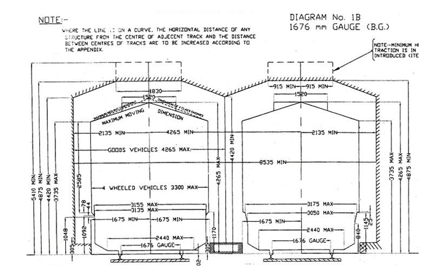 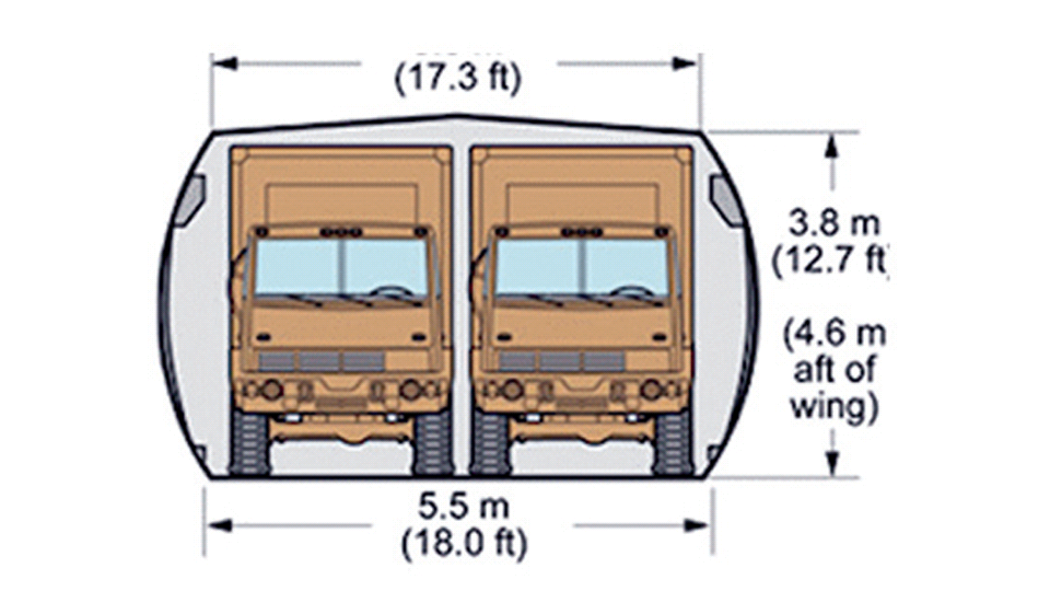 The above diagram is the ODC of C-17 Globemaster lll used by Indian Air Force for logistics purposes. Considering this a composite parameter of road, rail and air transport should be considered together for better transportability should be employed to evaluate both GNMBT designs the design that is Evolution and the one that is Revolution. ISTARIntelligence Surveillance Target Acquisition & Reconnaissance.In an era of net centric warfare an individual fighting unit isn't a lone wolf moving ahead and assessing the battle scenario itself but is connected to all the friendly forces and to the command centre. The GNMBT would surely be expected to be a tactical unit which is fully aware of the developments in the battlefield and getting clear directions from the command as well as actively benifiting from the friendly forces around. This network centric approach in a MBT involves the following systems and sensors as given as follows. • Battlefield management system (BMS) • Software defined radio (SDR) • Automated target tracker (ATT) • Commanders panoramic sight (CPS) • Gunners main sight (GMS) • Laser target designator (LTD) • Laser range finder (LRF) • Laser warning and countermeasure system (LWCS) • Drivers sight with thermal imager (TI) • Combat identification of friend or foe (CIFF) A video explaining ISTAR scenario.ISTAR is an advanced multi-dimensional and configurable decision support set of tools, adaptable to all command levels, from national HQ to battlefield commanders. It assists in achieving intelligence dominance for the net-centric battlefield by providing decision makers (commander in MBT) with a real-time situation picture of the theatre. It greatly increases a Tank’s situational awareness thus increasing the survivability. While integrating ISTAR tools with the GNMBT its weight, size and power consumption would be primary considerations and the extent to which these tools adapt to the considerd Evolutionary or Revolutionary designs would be a deciding factor as to which one fares better.Theatres of Operation.Indian Subcontinent is blessed with a varied terrain that consists of a combination of Snow and Boulders in J&K, The salt over layer in the Rann of Kutch, The swamps of the delta region of Ganges in the Bengal, The dense vegitaion in the North East, The sands of Thar and a mixed terrain of medium boulders, vegetation in Punjab. All these are possible theatres where battles have happened and may happen. While India has an experience of fighting the largest ever post WW2 tank battle in 1965 war. The challenges that occur in Deserts and Plains are well documented. But the information related to challenges occurring at high altitude battles is not much available. As a general consideration at high altitudes, extreme temperature (sub-zero), logistical challenges (>30° gradient), high power requirement (air density less than 50 per cent compared to mean sea level) and material failure are of the major challenges encountered. 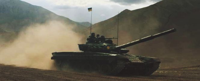 The GNMBT be it an Evolution or a Revolution would be expected to always perform the best possible in any of these ambient conditions. While evaluation is done in these regards the subsequent derived designs of various other armoured vehicles originating from GNMBT should also be considered. THE FINALISED CONFIGURATION The designs pitted in the beginning were thus evaaluated and it is observed that although similarities exist with respect to armament system, ammunition autoloader and transportability, they differ vastly with respect to survivability, cruising range, ISTAR, tactical mobility, trafficability and ease of adaptability. The revolutionary design as compared to the evolutionary design conforms to integrated survivability but with minimum armour. This pit mounted configuration not only provides higher cruising range but also enough space for packaging ISTAR systems. In addition, the revolutionary design caters to superior terrain accessibility, agility and soft soil trafficability that translates it into a weapon platform capable of superior mobility in a variety of terrains. Finally, this configuration is capable of adapting itself with ease into a universal combat weapon platform for executing multi-mission requirements of the users. It clears difficulty of choice in between the two designs and provides a clear view as to which one fares better considering all the parameters. 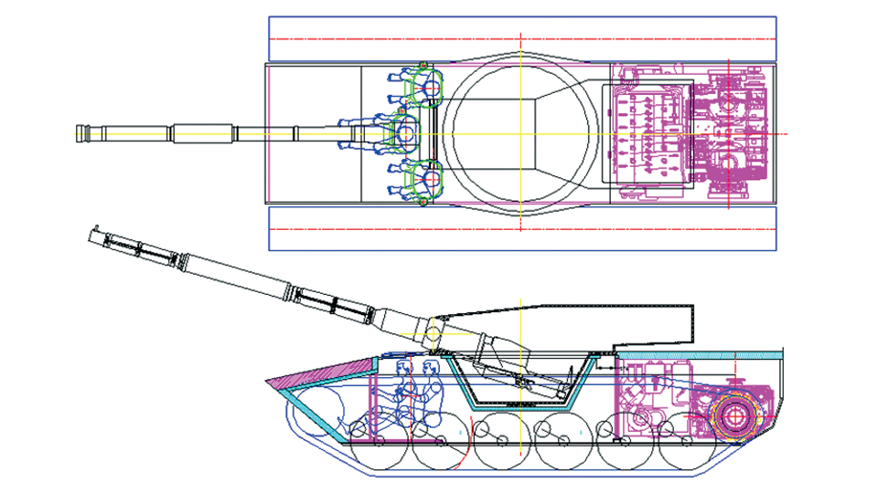 ( preliminary design of The GNMBT ) •1 While evaluating tactical mobility and trafficability it is observed that the revolutionary design with least nominal ground pressure NGP and mean maximum pressure MMP coupled with higher power to weight ratio is capable of achieving superior terrain accessibility and agility. The NGP is the ratio of vehicle weight to contact area. The MMP represents the average of the peak pressures that occur under each road wheel. •2 Comparing Mobility parameters the revolutionary design has low soft soil sinkage and higher trafficability across a range of terrains namely hard, clay, soft sand, marsh etc. On the transportability front, both the configurations have road, rail (ODC Class A) and air transportability (C-17). •3 Finally the Revolution configuration ensures that different platforms such as self propelled (SP) howitzer, heavy infantry combat vehicle (ICV), bridge layer tank (bLT) etc, can be easily adopted with ease and flexibility thus serving as a perfect universal combat weapon platform. DISCLAIMERThe data presented in this article is what available in public domain and was made available in a paper published in Defence Science Journal Vol. 67, No. 4, July 2017. It is available on DRDO’s website and no confidential info has been published anywhere in the article. The article should not be copied unless permitted by any of our admins. you may simply share the article. 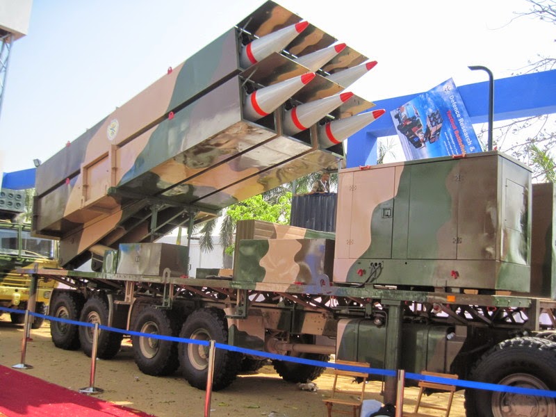 India is placed at such a place in this world that it has got some highly volatile neighbours. A China which keeps extending it's pre defined boundaries violates international pacts and subjugates other's opinion. A Pakistan which always had an unstable history of Military Dictatorship overthrowing a democratic government and invading India. After 1999 when Pakistan acquired nuclear weapons with the help of China, they described their nuclear capability as ‘minimum credible deterrance’ to prevent high intensity invasion from India. They successfully developed what they describe as developed as a "low-yield battlefield deterrent” tactical nuclear warheads. To deploy these nukes they developed a weapon system which is said to be targeted at "mechanized forces like armed brigades and divisions”. Under India’s no first use doctrine, the country would absorb the first nuclear strike and then should have adequate residual capability for the second strike. As pointed out by W.Selvamurthy, Chief Controller of Research and Development (Life Sciences and Human Resources) of the Defence Research and Development Organisation (DRDO), since India is wedded to the doctrine of no first use of its nuclear weapons, it needs to have a robust second strike capability. In the ultimate analysis, the class and range of missiles in the Indian arsenal should be capable of giving Indian defence forces a head-start in the warfare involving conventional weapons and nuclear devices and ensure the territorial integrity of the country against any misadventure from the belligerent neighbours.  Prahaar is a solid fuel Surface-to-Surface guided short range tactical ballistic missile developed by Defence Research and Development Organisation of India. It is specifically designed for tactical strikes against close range targets and to provide Indian Army with an all-weather , quick reaction , cost effective , high accurate battle field support tactical system to strike tactical and strategic targets. 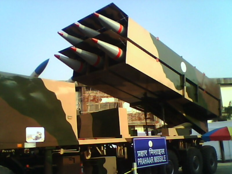 What is a Tactical Ballistic Missile System ? 1. It is designed for short range battlefield use and mainly the range is limited to 300 kilometres. 2. Tactical ballistic missiles are usually mobile to ensure survivability and quick deployment, as well as carrying a variety of warheads to target enemy facilities, assembly areas, artillery, and other targets behind the front lines. Warheads can include conventional high explosive, chemical, biological, or nuclear warheads. 3. Tactical ballistic missiles fill the gap between conventional rocket artillery and longer-range short range ballistic missile. Tactical missiles can carry heavy payloads deep behind enemy lines in comparison to rockets or tube artillery, while having better mobility and less expense than the more strategic theatre missiles. Additionally, due to their mobility, tactical missiles are better suited to responding to developments on the battlefield. 4. Newer air defense systems have improved ability to intercept tactical missiles, but still can not reliably protect assets against ballistic missile threats. This allows a moderate force of missiles to threaten a superior enemy by penetrating their air defenses better than with conventional aircraft, while providing a deeper strike than conventional artillery. 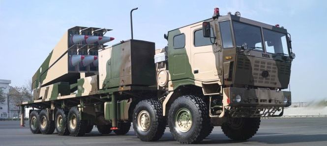 Development :- |
AuthorPalash Choudhari
Categories |
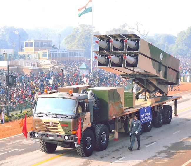
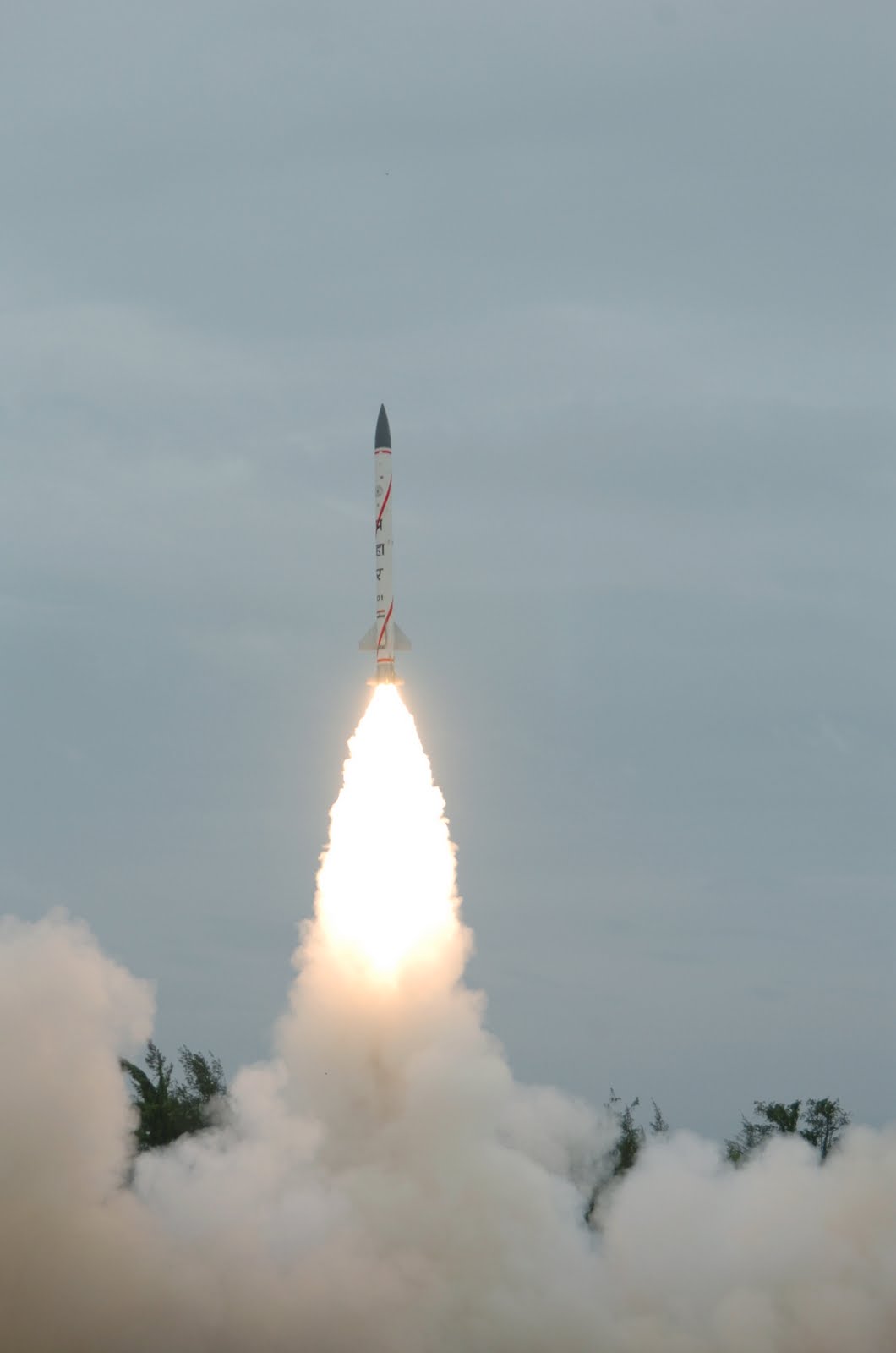
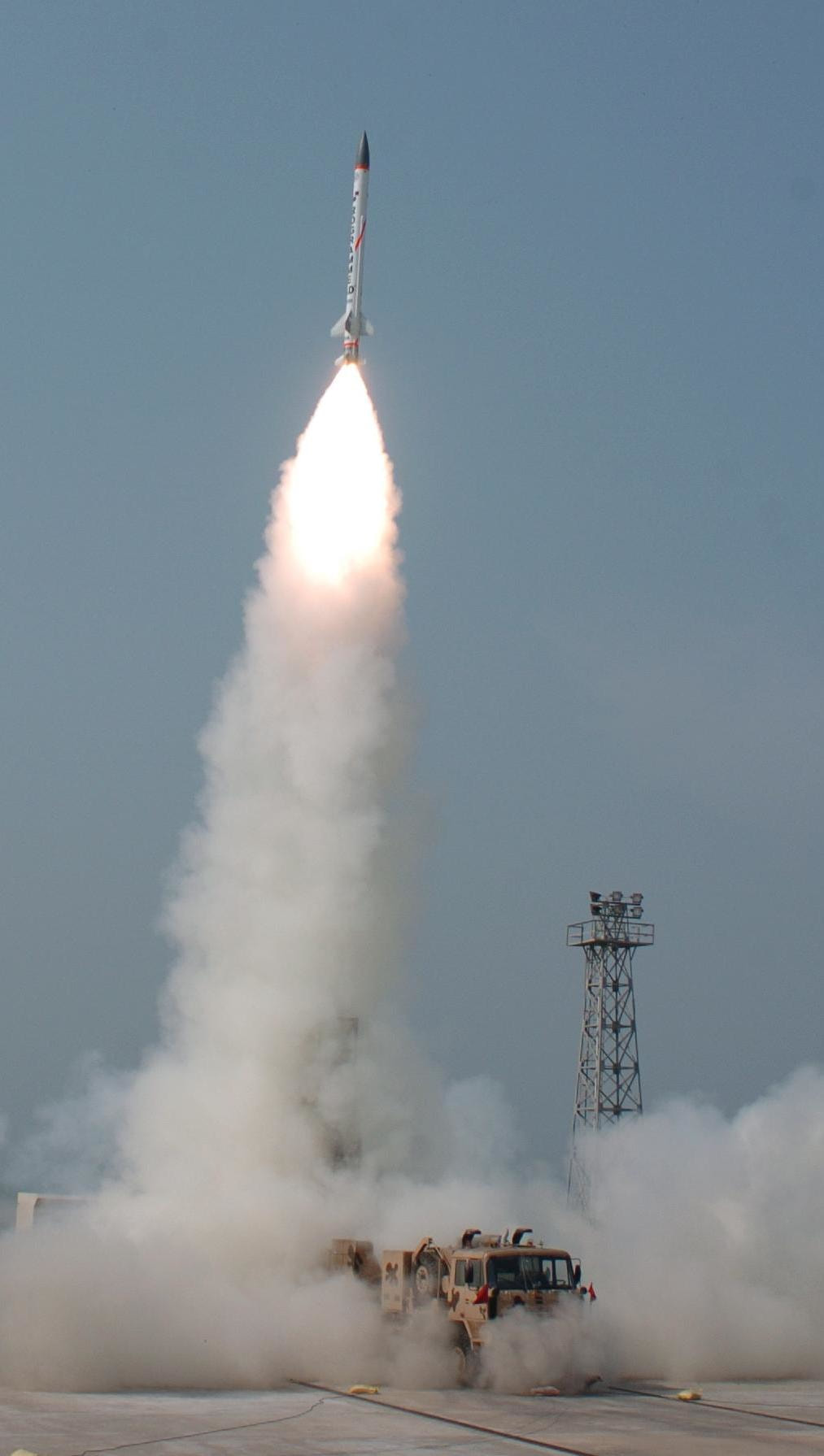
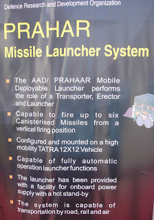
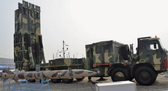
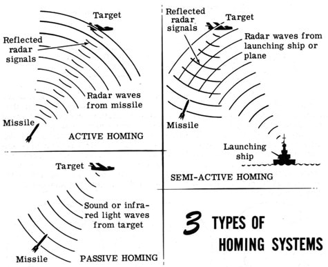
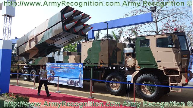
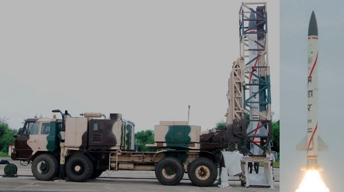
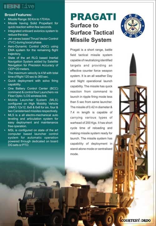
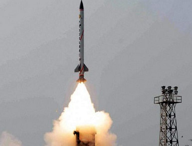
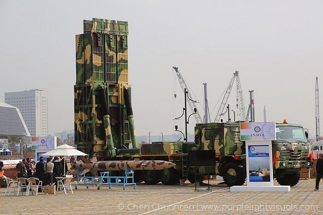
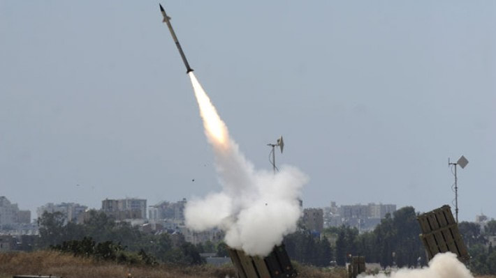
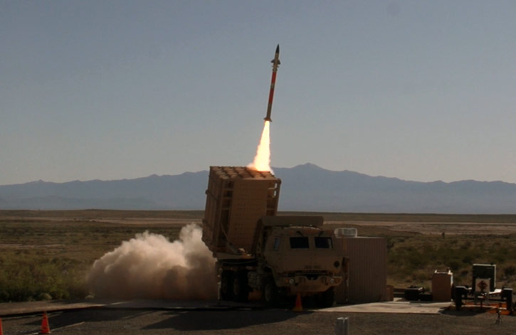
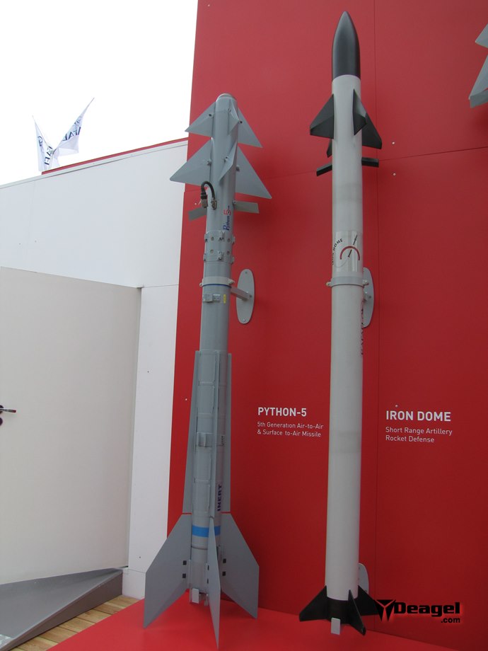
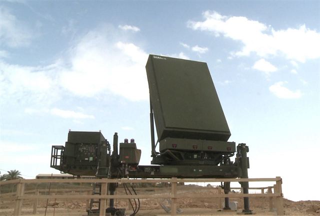
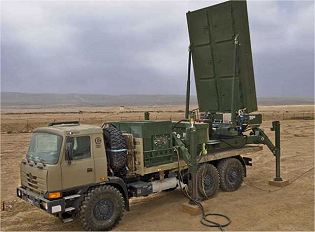
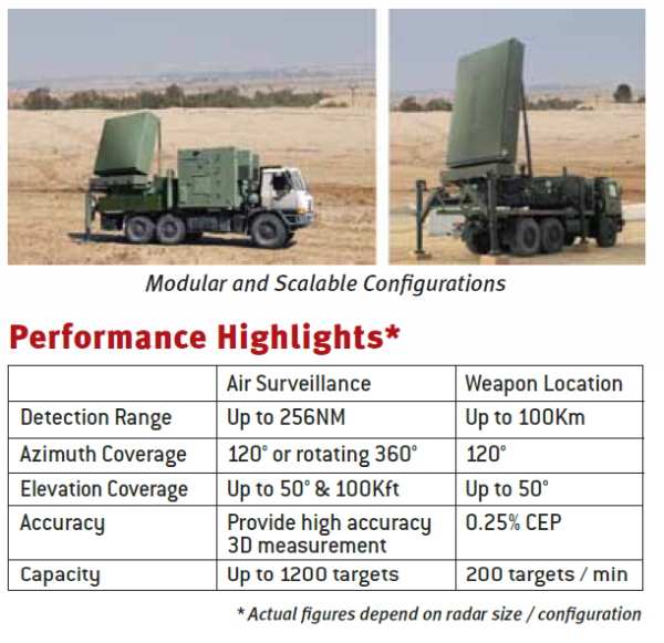
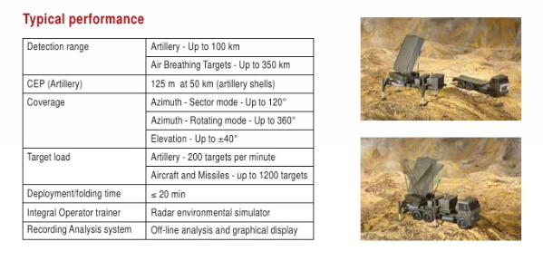
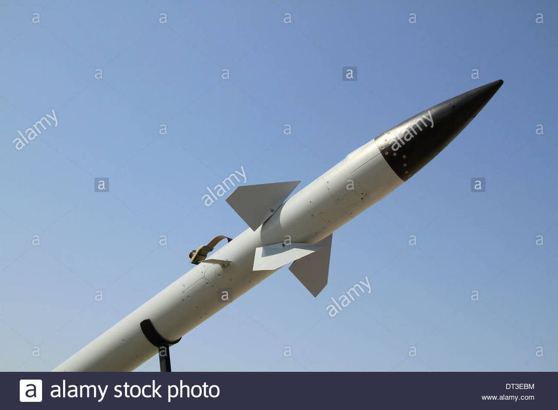
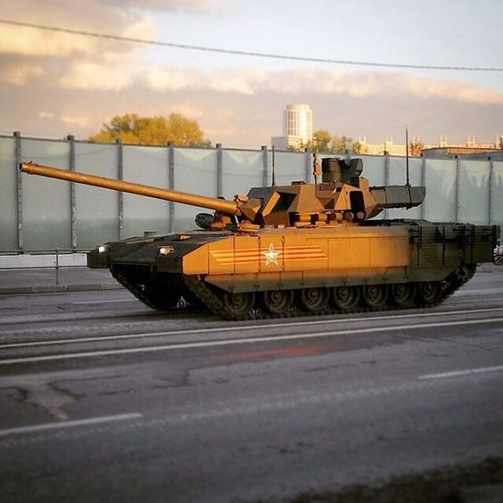
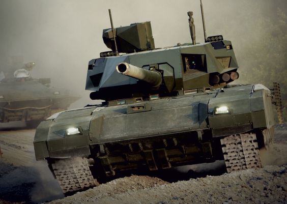
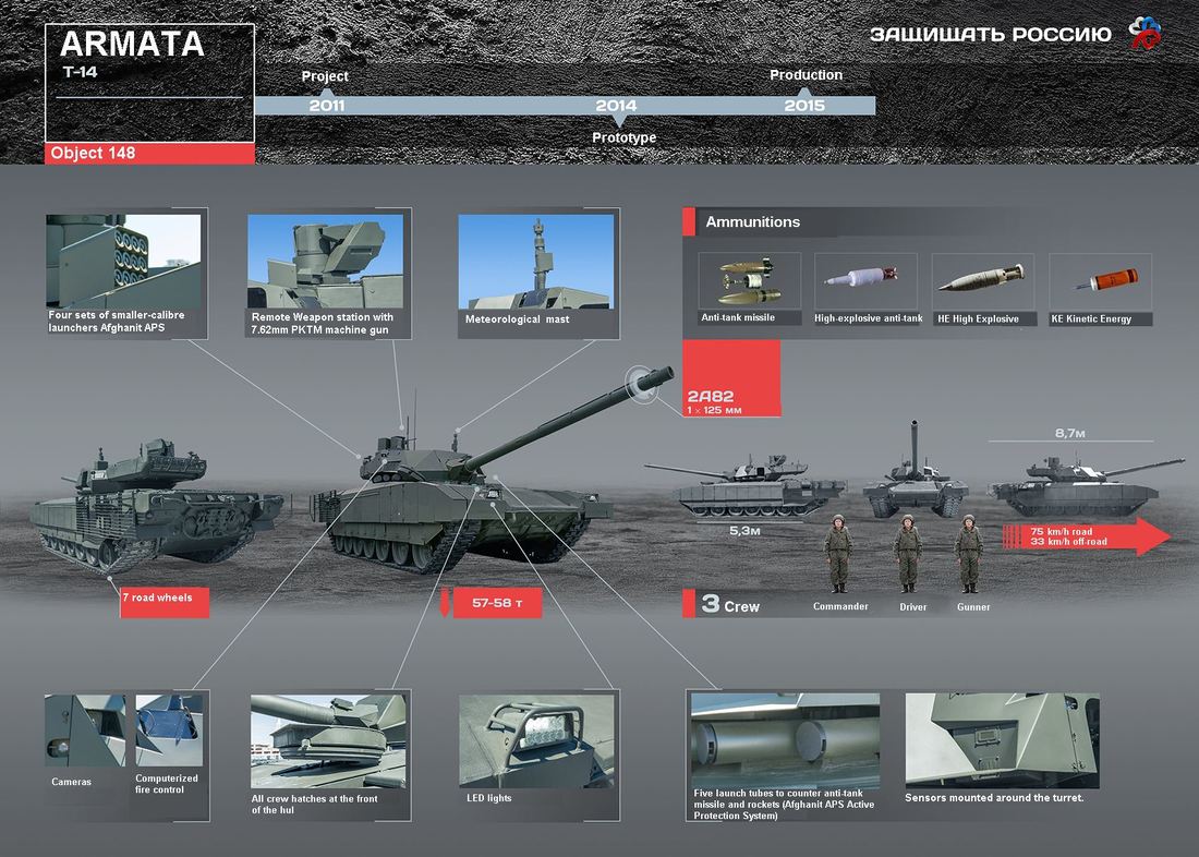
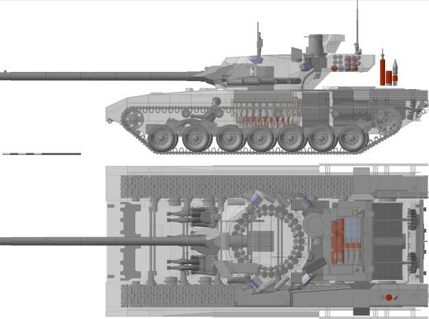
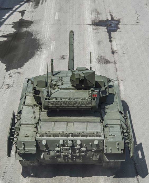
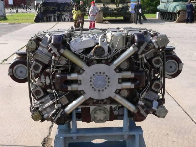
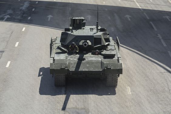
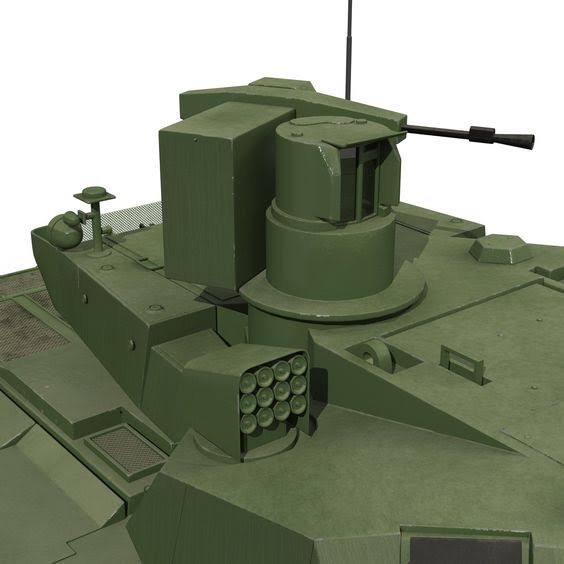
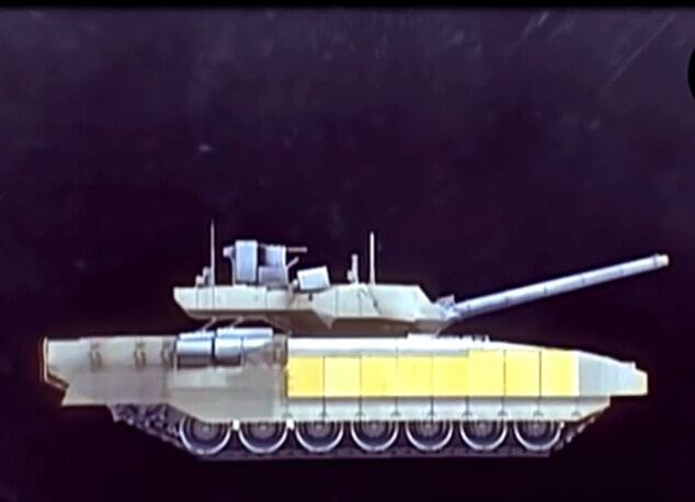
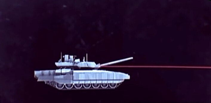
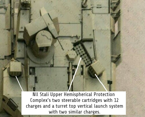
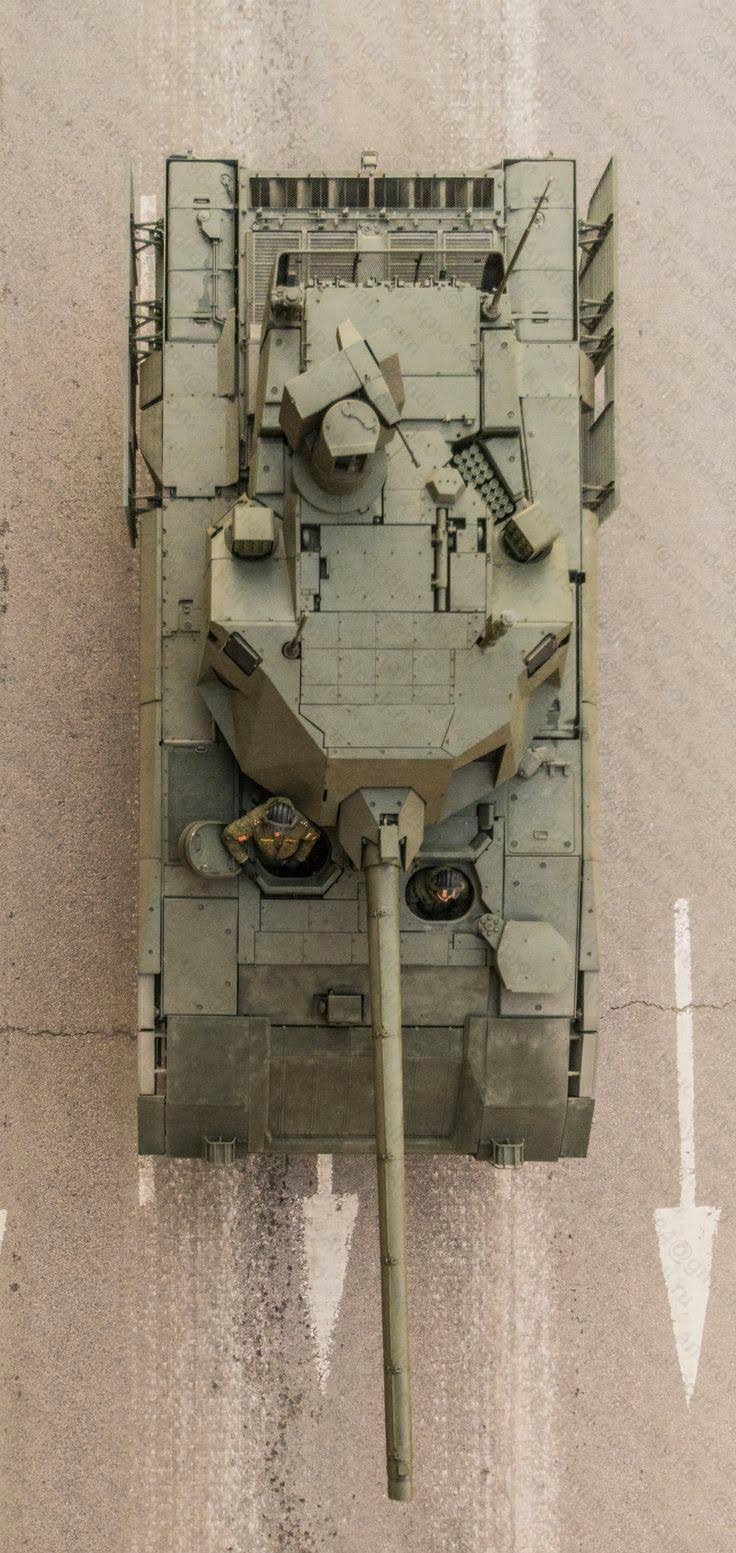
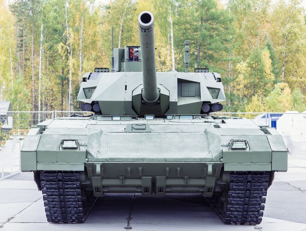
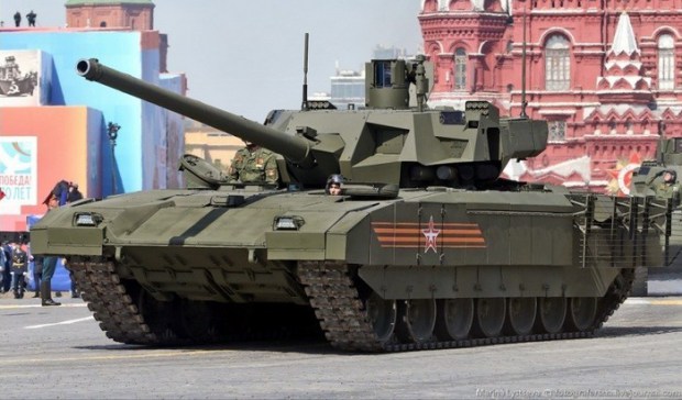
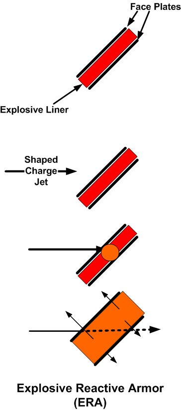
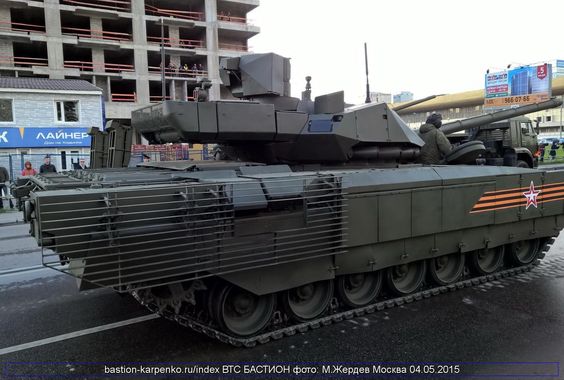
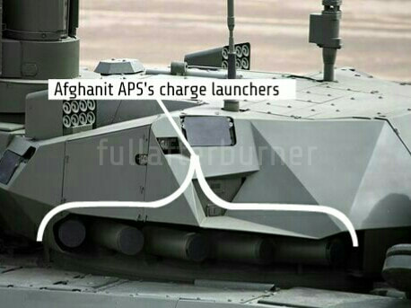
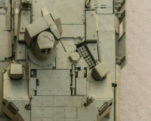
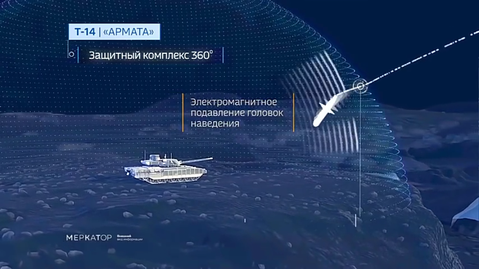
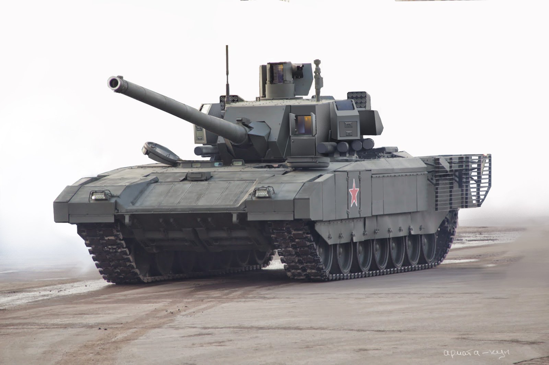
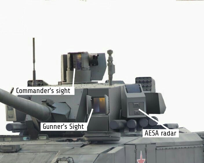
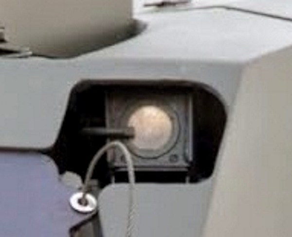
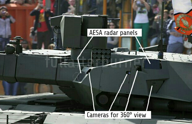
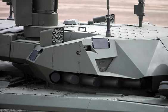
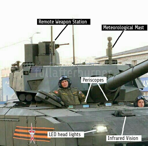
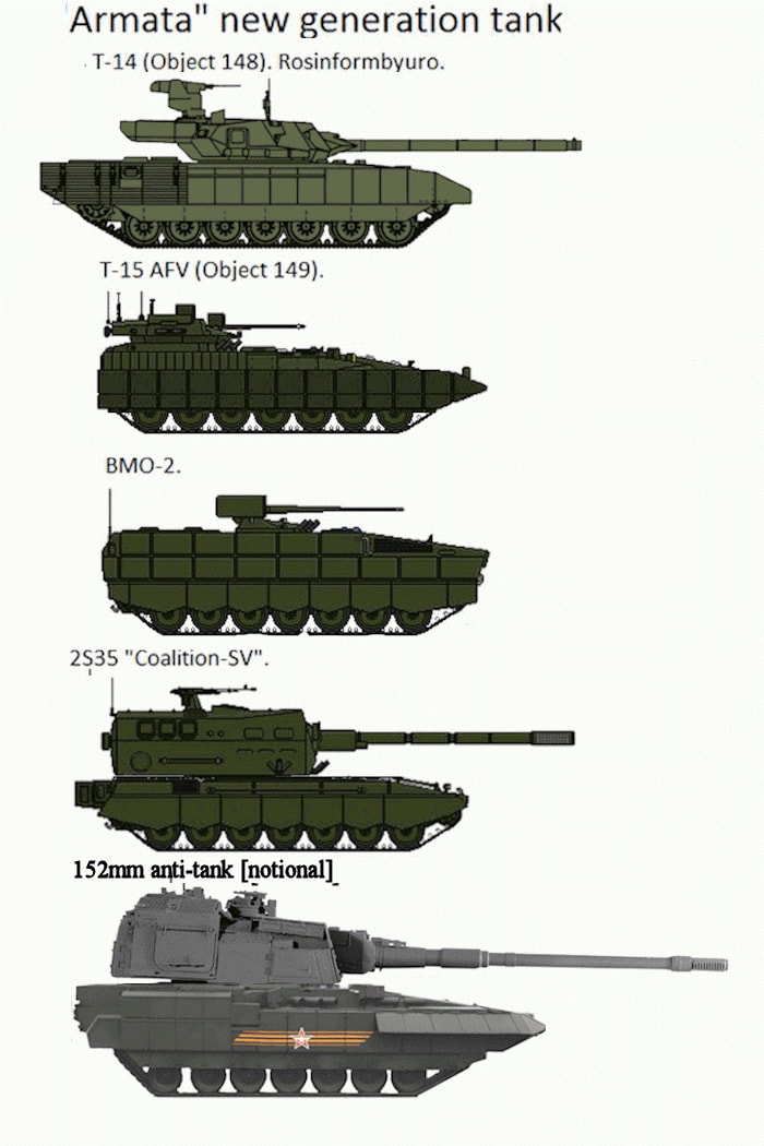
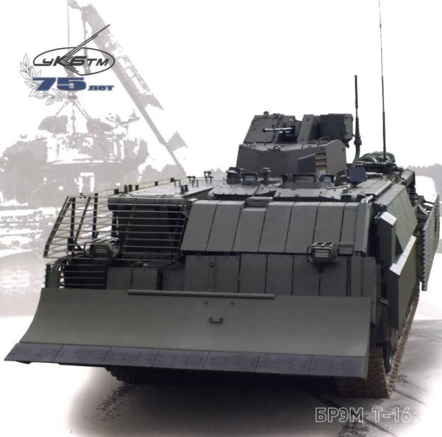
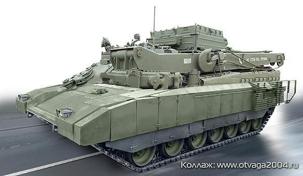
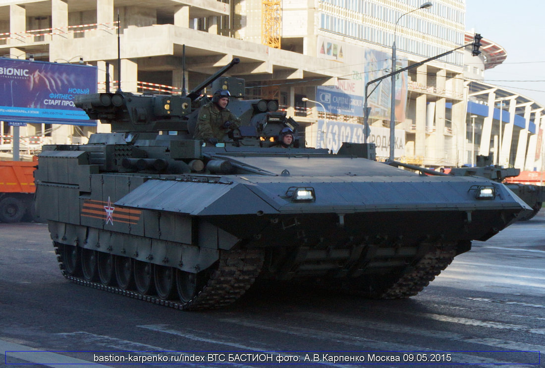
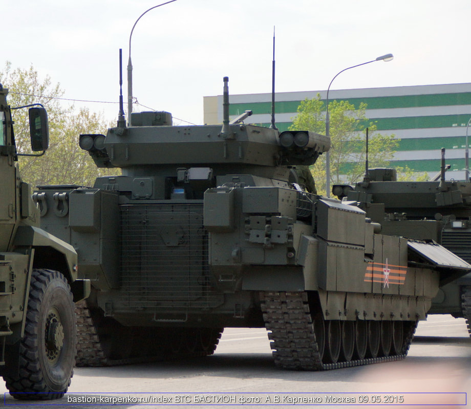
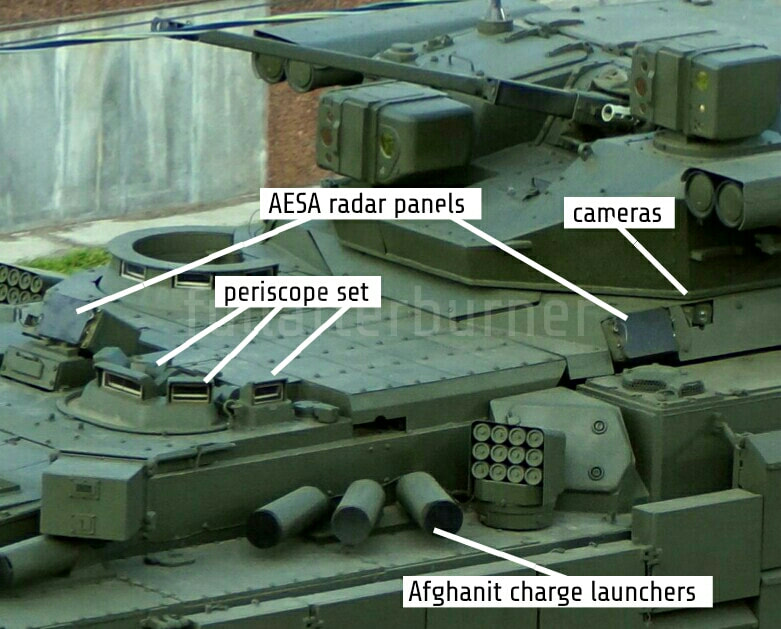
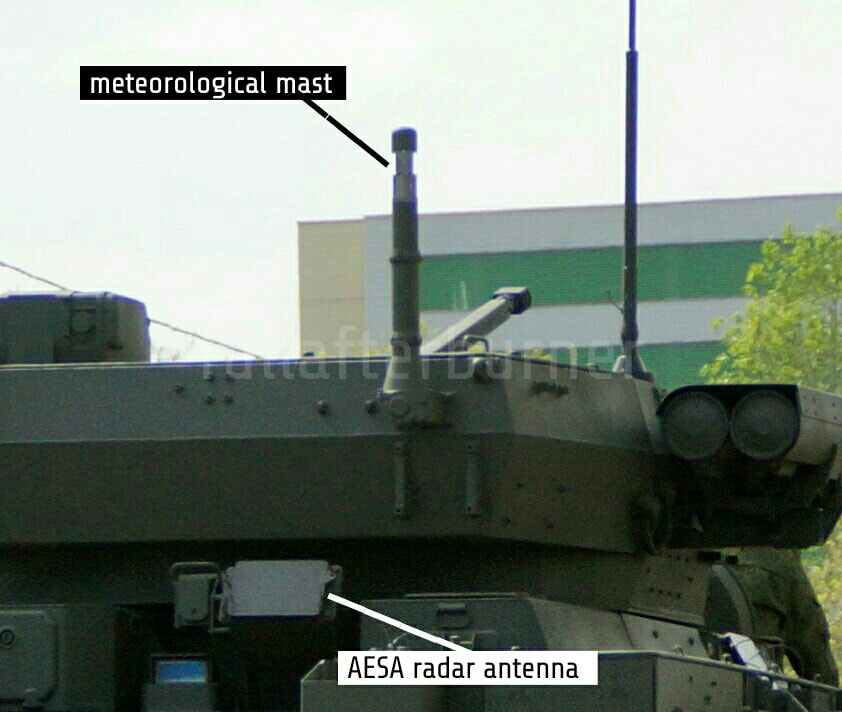
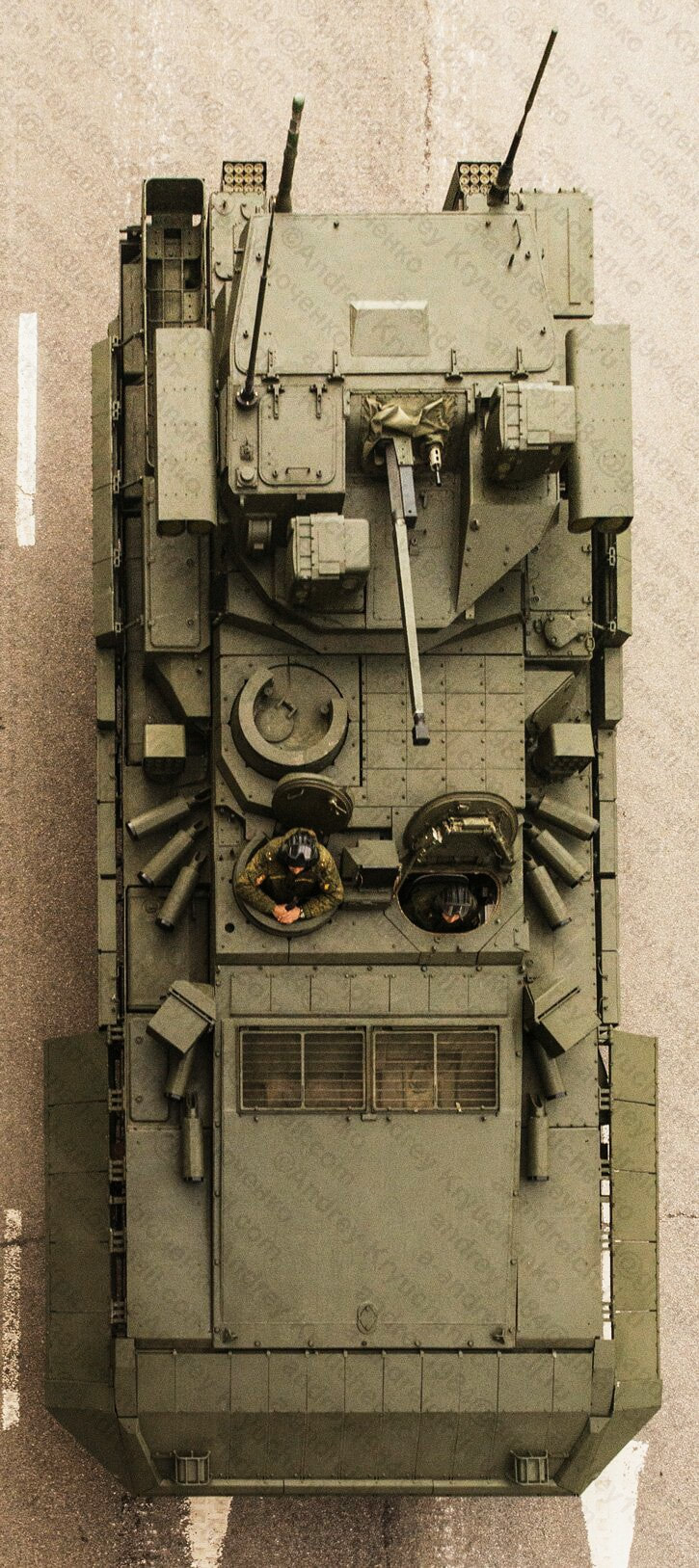
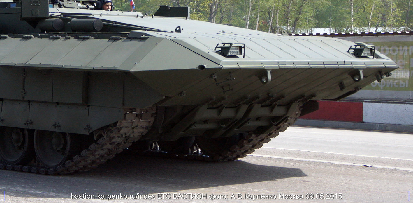
 RSS Feed
