|
This article covers India’s quest for rocket artillery systems in detail. 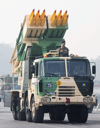 Pinaka MBRL The usage of rocket artillery dates back to India’s 1857 revolt against the British when Tipu Sultan used rockets tipped with blades. These rockets had metal casings and had a range of about 2kms. The blades used to randomly roll over the troops cutting them and inflicting heavy damages over them. Soon with rockets various aiming mechanisms, propellants, warheads as well as mobility systems began to develop along with modern artillery rocket systems. Conventionally the terrain in which Indian Army usually has to fight it's battles still uses gun based artillery systems. Throughout the world it is a debatable matter whether rocket based artillery is better or gun based. Whenever battles had to be fought for sustained longer runs gun based artillery is preferred, and if a fast attack is to be performed for movement of troops in a short term high intensity war, then rocket based artillery is used. 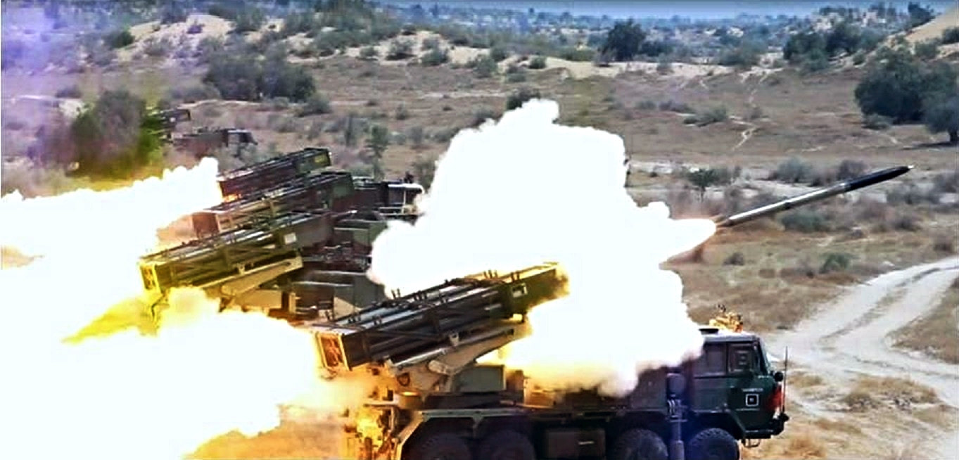 The name pinaka comes from the sacred trident owned by hindu god shiva. shiva's pinaka trident is his main weapon. Introduction.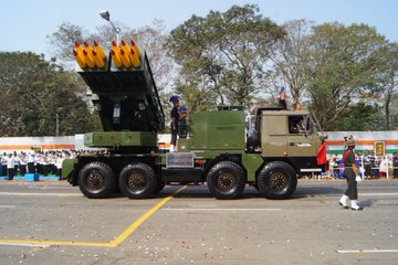 Pinaka MBRL was developed in India after the requirement of an indegeneous system to complement as well as replace the Russian Smerch and BM-21 Grad. The earliest introduction to modern Indian Military and DRDO of the artillery rockets came in the form of BM-21. There was no background information about the usage of artillery rockets in Warfare, no knowledge of materials and propellants, non availability of manufacturing expertise. The only visible option available was to reverse engineer available BM-21 Grad rockets and build a base of everything upon that. The emphasis was on the development of technologies related to rocket propellent, ammunition re-supply chain, warhead fuzes, launching mechanism. Organisations like HEMRL, PXE and ARDE were raised in the following process. What is an Artillery Rocket System???An Artillery system that uses rockets as a means to hurl projectiles at enemy troops. As described in the introduction the usage of artillery rockets have been a huge force multiplier for the military. In modern times locating enemy artillery and directing our artillery fire precisely at the positions of the enemy's artillery to neutralise their artillery even before they could act has become a useful tactic. In modern India when indegeneous rocket artillery development began there was no available literature about usage artillery in warfare or computational tools to test and calculate models. The Artillery Rocket System is used to inflict heavy damage on enemy in a short period of time. It is used on an enemy which is large in volume but has a relatively lower degree of protection. It is not used for sustained hours and hours of battles and is very costly if an enemy is pushing small volumes of troops and is using guerrilla warfare techniques. then rocket Artillery is not suitable against such force. 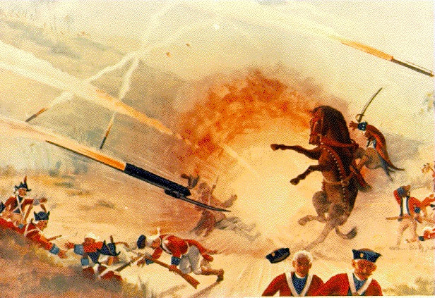 What is an Artillery Rocket??It actually depends upon whom you ask and which country you are. But in India, We have a very vague classification of Rockets. A propellant powered cylindrical casing which is unguided and delivers payload is a rocket. A propellant powered cylindrical casing which is guided but delivers payloads in space is an SLV (Satellite Launch Vehicle). A propellent powered cylindrical casing which delivers ammunition as a payload in enemy territory through a ballistic trajectory is a missile. Rockets have a high rate of collateral damage since their launch creates a lot of hot gases around the launch site, also it alerts the enemy quickly. Since rockets are unguided they are also inaccurate. A rocket consists of various subsystems which has to perform its tasks in sync for the sake of accuracy to reduce collateral damage and increase accuracy. ARDE has developed guided Pinaka rockets that have a GNC ( Guidance cum Navigation and Control kit). The subsystem of a rocket comprises the following. 1 Propulsion System 2 Rocket Fuzes 3 Stabiliser System 4 Warhead 5 GNC ( only in guided rockets) 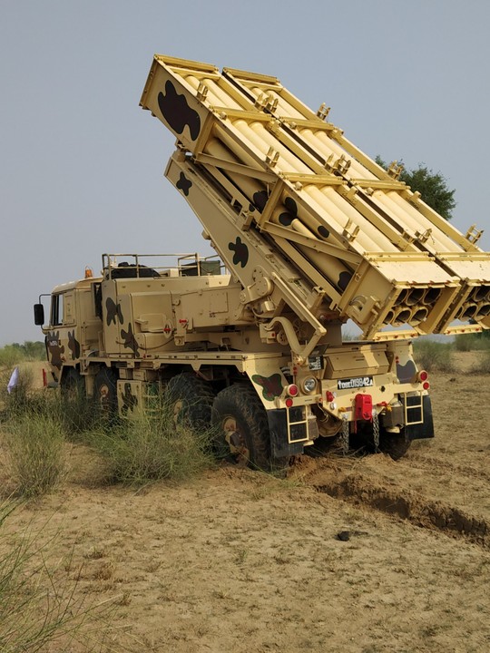 Design.The Design is a complex engineering process involving user requirements and analysis of Battlefield various scenarios. Analysis is carried out considering various aspects such as aerodynamics, propulsion, structural integrity and trajectory simulation, etc. The vibrations caused during multiple launches of rockets their firing order, their firing intervals also affect their performance. The whole design process of a system has to take all these things into consideration. The control system has to consider the errors that occur due to aerodynamic instability as well as vibrations during launch, elasticity of the structure, etc. 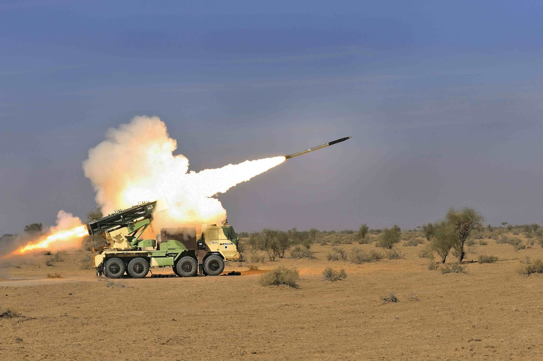 The entire launching mechanism as well as the rocket itself is analysed for heating. Structural analysis is performed on rocket casing and especially on the stabiliser so that smooth functioning could be performed. It has been optimised that if firing order and firing intervals are properly computed then for a certain target area at a certain rate dispersion can be reduced and hence accuracy can be increased. For doing this supportive tools in the Pinaka battery configuration are needed. All these optimisations are performed for a particular variant during design phase only. Due to geometrical and mass constraints rockets are designed with high slenderness ratio (L/D ~21) and multiple joints which reduces structural stiffness. Hence, rockets are susceptible to aero elastic problems like body divergence and fin flutter. Apart from aerodynamic loads, rocket structure subjected to internal chamber pressure due to propellant burning and ignition transient. 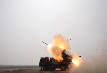 1 Propulsion Systems.Since these rockets are stored in containers and used occasionally it is obvious that Solid Propellants would be used in them. The propulsion system which uses Solid Propellants comprises of a cylindrical casing enclosing a propellant grain, a combustor/igniter at either ends of the cylinder and a nozzle to force out hot gases burnt after combustion. The igniter can be mounted either at the nozzle end or at head end. There can be one or many nozzles. The shape of the cross section of propellant grain is very significant, because it influences the manner in which burning would take place. When ignited, the propellant grain burns out radially outward forcing the hot gases through nozzle. The nozzles are designed to maintain some level of chamber pressure inside the casing, and casing design should also be in accordance to that. This video properly explains Solid Rocket Propulsion. A must watch. In India the most widely used propellant in Agni, Astra Missiles or PSLV rockets is HTPB. Hydroxyl Terminated Poly-Butadine HTPB is a very interesting fuel.HTPB is a mixture rather than a pure compound. It binds the oxidizing agent and other ingredients into a solid but elastic mass. The cured polyurethane acts as a fuel in such mixtures. It is used by ISRO’s PSLV and also Japanese SLV called M5. Being developed in various forms since the 1960s in India, The Composite Propellent used in Pinaka consists of HTPB, ammonium perchlorate and aluminium powder as major ingredients. The bonding agent, plasticizer and processing aid curing agent of undisclosed type is also used. These propellants hacked from the Soviet Rocket industry have high specific impulse and high density. The Pinaka Mk1, Mk2 and 122MM ER Rockets use this propellent. However better propellent is being pursued. The Composite Modified Double Base propellent is known to provide better specific impulse than the Composite Propellant currently used. The CMDB has more oxidiser compounds dispersed in it.  The Propellant Grain is either cartridge loaded or case bonded. The cartridge loaded ones are manufactured separately and then assembled into the casing while case bonded ones the casing is used as a mould and propellant is cast directly inside the case. The propellent can be manufactured by using either casting-moulding or could be extruded. While Pinaka Mk-I utilizes cartridge loaded grain, Pinaka Mk-II/ERR122 utilizes case bonded grain. For case bonded rockets the new propellant being developed is Nitrate Ester Plasticized Polyether (NEPE) propellant having high energy, high density and superior low temperature strain capability.  The Rocket motor casing is designed to be light weight as well as strong enough to sustain the chamber pressure experienced during burning of propellent. There are other aerodynamic loads that are exerted on the casing while following a ballistic trajectory cutting through air at very high speeds. The design of casing must take these loads into consideration too. Finally the available most easy and cost effective manufacturing technique should be used and selected material should be suitable to such a process. The thick hollow cylindrical casings are usually manufactured using a process called 'Flow Forming’. Flow Forming is a process by which low strength, low cost material can be formed into high strength, and more precise cylindrical casing tubes with considerably reduced mass. Flow forming is also suitable for mass production of such tube casings. In the Flow Forming process, a tube of metal is formed over a mandrel by one or more rollers using tremendous pressure. The roller deforms the workpiece, forcing it against the mandrel, both axially lengthening and radially thinning it. The entire process is cold worked, meaning the workpiece isn't heated additionally. The workpiece does get heated due to friction, because of which coolant fluids are constantly poured over it. Most of the time additional machining is even not required, just some finishing work might be needed. This is why this process does not produce wastage. Video of Flow Forming Process The material used in Pinaka is ESR grade AISI 4130 steel forging. This material though needs some heat treatment before forming to attain necessary mechanical properties.The required range of pre-form hardness, grain size and percentage thickness reduction meets the specified strength levels of rocket motor. Effect of various flow forming parameters like spindle speed, roller feed rate, roller geometric features like approach angle and roller nose radius were also studied and operating parameters for the flow forming of rocket motor were established. Thus the entire propellent system comprising of casing, igniter and propellant is a complex assembly of parts made out of careful manufacturing processes. All these elements are procured from private industries thus creating indegeneous defence industry. 2 Rocket Fuzes.The Fuzes are a combination of sensors and detonators, the sensors sense a set necessary condition needed for explosion to happen and the detonator causes the explosion. There are multiple types of fuzes based on application, warhead explosive type or activation mechanism. It depends upon the choice of Fuze or vice versa. In MBRLs the detonators ignite a chain of detonations ultimately reaching the main explosive. This main explosive is kept dis-aligned from detonator to prevent any accident on ground, it is aligned with detonator after launch. There are two main types of Rocket fuzes Variable Time and Electronic Time rocket fuzes. Variable Time Fuze / Proximity Fuze It is an old long used technique in artillery warheads. Prior to this the Fuzes were set to detonate after a fixed interval of time. But since the flight trajectory of Rockets used to vary a lot a new mechanism was needed to detonate at the time when warhead would have reached it's nearest to the target. So the Fuse mechanism would consist of an element that would sense it's nearness to the target and another element that would keep it in safe/unarmed condition before launch and would prevent accidental detonation.  The modes of VT fuze used in Pinaka MBRL are Proximity and Point detonation. During point detonation mode the rocket’s impact switch initiates detonation when the warhead hits the ground. In this mode the warhead uses ‘restricted high explosive’ RHE or Pre Fragmented PF. There are a huge number of mechanisms developed around the world to cause detonation on impact. These mechanisms are well researched to cause detonation in multiple cases of hitting, like hitting a steep object and slightly touching it, causing a few seconds of deliberate delay after penetrating the target. Certain Mechanisms could be super sensitive and would detonate at the slightest physical contact with any object. There are safety mechanisms in fuzes to prevent detonation before firing, we would discuss them separately. It is unpredictable as to how the warhead would impact and point detonators vary accordingly. During proximity detonation, the detonation occurs when the warhead reaches to a close preset proximity of target. The proximity fuze uses sensors to determine its proximity with surrounding physical objects. Over the period of time many sensors were developed for sensing proximity. There may also be a combination of two or more sensors working in sync. There are mostly radio frequency based sensors, otherwise active sonar, passive acoustic, infrared, magnetic, photoelectric, seismic or even television cameras are used. Since the rocket would be handled by friendly military personnel before launch, the proximity fuzes also have safety mechanisms that keep fuzes in safe mode and automatically selects armed mode after launch. Electronic Time Fuze This type of fuze causes detonation after some preset time, time is calculated by one or a combination of many mechanisms or electronic circuits. This type of fuze is used when warhead is Incendiary or Sub-munition type. We will discuss warhead types further down the article. The ET fuze is a more common practice today as it may be remotely put in self destruct mode if accidentally fired on a wrong target or it may land unexploded in similar case. In Pinaka the Submunition Warheads are released while warhead is still in air. The warheads are released by rotating force acted on them by a rotating module, which is activated at a preset time in trajectory by the ET mechanism/circuit. The Sub-munitions require multiple electrical pulses for detonation. DRDO also claims to have developed Thermal Battery and Turbo Generator based ET fuzes.  The Sub-munitions or bomblets dropped by the main warhead, contain their own independent ET Fuze. They have Direct Action Self Destruct DASD fuze which detonates either on impact or after a 20 seconds delay. This DASD fuze gets armed only after being released from the main warhead. Apart from the above discussed Fuzes there are many types of Fuzes like remote detonation fuze, barometric fuze, etc but in India they aren't usually used.  Safety and Arming Mechanism This mechanism, as discussed previously, keeps the Fuzes in ‘safe’ mode before launch and automatically switches to 'armed’ mode after launch. There are multiple safety and arming mechanisms across the world. The one used on DRDO Pinaka consists of two parts, the latching G Switch and Gaine. The latching 'g' switch serves two purposes: The first purpose is to connect the battery to an electronic circuit so that the firing circuit starts working. The second function of latching 'g' switch is to remove the obstruction to shutter of gaine so that the explosive train starts its alignment. The latching 'g' functions only when sustained acceleration of 12-18 'g’ is imparted by the flight of rocket. Gaine aligns the detonator from 'SAFE Condition' to 'ARMED Condition' after safe separation distance (300 m) of rocket from launch point. This is done by star wheel, gear, pinion and pallet mechanism. The detonator inside the shutter comes to the armed position slowly. The motion of shutter is continuously hindered by the pallet and therefore it takes time (about 900 ms–1 s) for the detonator to come to aligned condition. 3. WARHEADSThe tip of a missile/rocket which contains explosives is called a warhead. Although explosion is the primary purpose,there exist some non lethal warheads that only incapacitate its target. Warheads are mounted on Torpedoes, guided and unguided munitions as well. There are several types of warheads whose nature depends upon the intended damage. Various warheads have been developed by DRDO for applications ranging from SAMs to Anti Tank munitions, we would mostly discuss only those who are designed for Pinaka MBRL. Pre Fragmented WarheadsAs the name suggests the warhead consists of small pieces of metal packed inside a cylinder that explodes, releasing these pieces around and causing physical damage to it's target. The Pre Fragmented type warheads are therefore used for non armoured targets such as radar installations, fuel storage facilities, personnel inside a bunker or building. This warhead has a VT fuze to detonate at a predetermined distance above the target to achieve maximum damage. The PF warheads used in Pinaka are effective upto 60m radius. The warhead consists of 6mm tungsten alloy spheres as fragments laid over a fibre reinforced plastic module wound by filament. Inside this fibre reinforced plastic module, is the newly developed DENTEX explosive. The DENTEX is a mixture of several other explosives like RDX,TNT,etc. The energy liberated on detonation of the explosive is carried by the high density fragments surrounding the explosive column. These fragments are lethal at even large distances and typically employed against soft skinned targets.  Incendiary WarheadsThe incendiary warheads are designed to start a fire so that the fire destroys everything around. Mostly used against ammunition storage, fuel storage or places having high density of military personnel such as a small camp of tents. There are international laws to prevent use of such weapons against civilians or military targets within civilian proximity, during world wars these weapons warheads were blatantly used. The composition used in Indian incendiary warheads is a 60:40 ratio of Zirconium and Red Phosphorus. There multiple compositions used world wide most notably Napalm, Thermite. The composition is housed inside a containment with burster charge, the burster charge is the same thing that causes your fireworks to explode in sky and spread stars. These containers are sealed leak tight and five such containers are assembled in a steel tube. The steel tubes are arranged around in a nose cone as shown in picture. The steel tubes themselves are designed to rupture and cause secondary fragmentation and hence more damage. The individual steel tubes are released at some distance above ground using ET fuze and causes a destruction in around 75m radius.  Submunition WarheadsThe Sub-munitions or bomblets are smaller warheads packed inside a main warhead casing. They are released over a large area by an ejection mechanism which causes them to spread and cause multiple small explosions over large area. Each submunition/bomblet have it's own fuze. The casings would cause fragmentation to maximize damage and are designed to cause heavy structural damage to major components. The ARDE has developed three types of Sub-munitions namely DPICM Dual Purpose Improved Conventional Munition, ATM Anti Tank Munition and STM Soft Target Munition.  DPICM Submunition.This small bomblet works as a bomb itself, it has a ribbon stabiliser, a fuze and mostly shaped charged warhead, shaped charge will be explained later. The point detonation fuze activates on impact and if it fails, the self destruct mechanism causes explosion. The name Dual Purpose means that sub-munitions use both explosively formed penetrators for anti-armor work and fragmentation for antipersonnel work. To properly disperse the submunition the important functions happen simultaneously, Ballistic case cutting by Flexible Linear Shaped Charge and High gas pressure generation at centre by the central buster. These functions are initiated 750m above the ground. These simultaneous functions eject each bomblet out and later on the bomblets independently strike the targets. This small bomblet works as a bomb itself, it has a ribbon stabiliser, a fuze and mostly shaped charged warhead, shaped charge will be explained later. The point detonation fuze activates on impact and if it fails, the self destruct mechanism causes explosion. The name Dual Purpose means that sub-munitions use both explosively formed penetrators for anti-armor work and fragmentation for antipersonnel work. To properly disperse the submunition the important functions happen simultaneously, Ballistic case cutting by Flexible Linear Shaped Charge and High gas pressure generation at centre by the central buster. These functions are initiated 750m above the ground. These simultaneous functions eject each bomblet out and later on the bomblets independently strike the targets. STM/ATM Submunition.Both are designed to quickly lay air dropped mines to deny mobility to armoured columns or columns of troops supported by high mobility vehicles. The STMs have pressure activated fuses that burst upon application of a set pressure even if pressure don't act for a certain period of time the STMs initiate self destruct function to clear the field. The ATMs have a magnetic sensor that senses the tanks around. The ATMs when get dropped activate a small parachute for stabilisation, the parachute gets released once the submunition near ground. The bomb has leaflet like pyrocutters as shown in picture which helps it to stand upright after hitting the ground. Once all bombs/mines are laid the magnetic sensors are activated. If the magnetic sensors don't sense anything the self destruct mechanism explodes the Munition.   Thermobaric WarheadThe term Thermobaric refers to both temperature and pressure in Greek language. Thermobaric explosives are the most destructive ones and are used against heavily armoured targets. They are also named Fuel Air Explosives, Heat and Pressure bombs or Vaccum Bombs. 4 Stabiliser Systems.Rockets move through air and anything that has to move through air has to consider the delicate balance in between Centre of Gravity and Centre of Lift. The CG is where all the mass of a body is concentrated and CP is where the net resultant aerodynamic force would act. The position of CG is always fixed in a solid body as solids have definite shape, the position of CG is shifting in liquids. This is also one reason why solid propellant rockets are preferred over liquid propellant ones. To give a sense of what CP is let's assume that you are in a moving car with your hand out of the window. Assume your hand is holding a cylindrical tube only using two fingers. Since the car is moving aerodynamic forces will act on the cylindrical tube and would force it to move. Now imagine holding this tube in an upright position only allowing a pendulum like motion with your two fingers still holding it at the centre and acting as a pivot. The location where you would find the tube perfectly balanced in the airflow is the location of centre of pressure CP.  In the above discussed example the angle of attack of tube on the wind is 90°. When a rocket moves through air it's Angle of attack constantly keeps changing, so does it's CP. Our fireworks rocket often spiral out of control only due to this shifting of CP relative to CG. The net resultant force of CP and CG decides which direction the rocket would go. To stabilise this the rocket is rolled constantly by find that are attached in such a way that they provide rolling motion to rocket. The fins also used to be attached on Arrows fired by Bows for a similar reason. Rolling enabled by fin stabilisers ensure greater aerodynamic forces in the aft section of rocket and also ensures that CP would constantly be behind CG throughout the flight trajectory. To understand more please watch the video. Apart from aerodynamic forces a rocket may deviate due to thrust misalignment. As there is a slight error assembly and cylindrical rockets may not be perfectly perpendicular to the vertical axis. Traditionally artillery rockets and ATGMs that are housed inside a canister have Wrapped Around Fins WAFs. The roll maneuver performed by rockets minimises the effects of thrust misalignment and also provides separation between pitch and roll frequencies. The Mk1 Pinaka used curved WAF so that they can perfectly match with cylindrical periphery of rocket and aid in packaging inside canister. But the curved WAF due to flow asymmetry generates side forces and out of plane moment at high Mach numbers and hence, are prone to dynamic instabilities. In case of Pinaka MkII, the rocket was initially configured with curved fins, however, dynamic instabilities were observed at flight speed of 3.4 Mach. The major problem of dynamic instability was successfully overcome by switching from curved wrap around fins to flat wrap around fins configuration as shown in Figure. Spin and acceleration profiles, which were erratic in case of curved WAF, became smooth and inline with the prediction in case of flat WAF indicating a stable flight.  While designing the stabiliser the designer must take into account fin chord, fin span, cant angle and plan-form area. The general shape of fins in early rockets and missiles used to be either clipped delta or trapezoidal shape. Modern rockets use Thrust vectored nozzles which gives very high maneuverability.  Pinaka Rocket Pod.A rocket pod consists of several launcher tubes assembled together. The Pinaka system rocket pod consists of an integrated assembly of frame, launcher tubes, wire harnessing and lock assemblies meant for clamping and wire harnessing. The pod frame is made of extruded sections (mostly angles) of aluminium alloy. The frame carrying launcher tubes can be used as a storage/transportation container. Unlike the smerch system which has individual launcher tubes, the Pod frame of Pinaka has been designed keeping to offer flexibility for using rockets of different calibre. In general artillery terms calibre means diameter. Since there are different calibre rockets one same pod frame can be reused to assemble launcher tubes of various diameters/calibres. These pods are fitted atop a mobile launcher. The launcher tubes are expendable and can be used only once and have to be discarded after firing. Having a pod frame the launcher tubes can be removed and frame can be reused fitting it with new tubes. The Pinaka has six tube pod frames for mk1, mk2 and mk1 enhanced and has four tube pod frames for guided Pinaka. The launcher tubes developed for these rocket pods are disposable/one time use and are made from E-glass epoxy resin system based composite and manufactured by filament winding process. 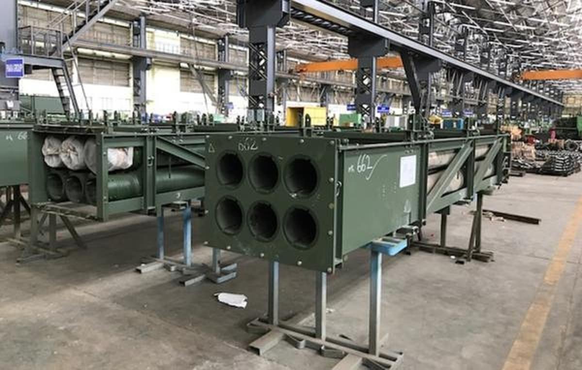 The launcher tubes on smerch or the Chinese A-100 MLRS systems consist of fixed launcher tubes where only one type of rocket can be fitted. The A-100 MLRS exported to Pakistan has fixed launched tubes of 300mm Artillery calibre. The A100 artillery rocket system has 10 launch tubes for 300 mm artillery rockets (the original Smerch has 12 tubes). Chinese manufacturers claim that the A100 is not compatible with the 300 mm rockets of the Smerch. They also insist that Chinese rockets use different propellant motors and components. A standard rocket is 7.3 m long and weighs 840 kg. A variety of warheads are available, including High Explosive Fragmentation (HE-FRAG), fuel-air explosive, and cargo warheads. It is claimed that the A100 MLRS has a maximum range of 120 km, versus 90 km of improved Russian Smerch. Newer improved Chinese MLRS are being seen in a pod frame configuration. Pinaka Configuration in Detail.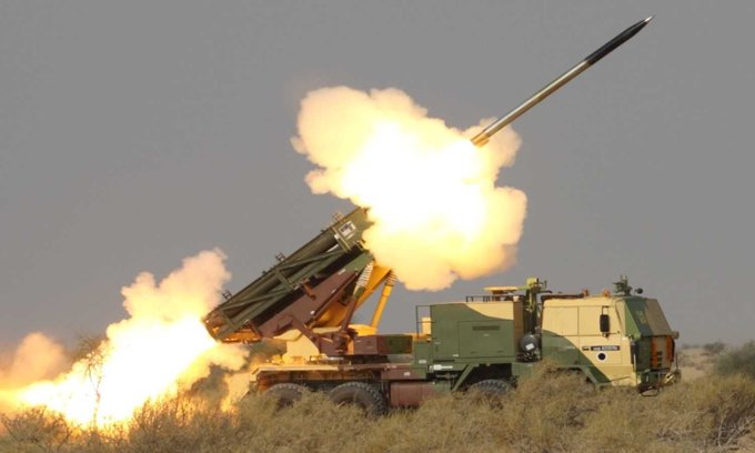 It's not just about the rockets and launchers pod, the Pinaka is a whole system that works in sync to deliver unmatched firepower to its user. The entire system consists of the Mobile Launcher which is fitted with rocket pods, A loader cum replenishment vehicle, a normal replenishment vehicle(with no crane). A mobile command post, DIGICORA MET Radar. The entire system is integrated with ACCCS Shakti system of Indian Army that provides theatre command and control to Indian Army commanders. Launcher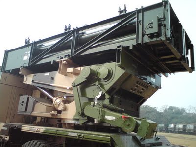 The launcher is a 2 axis revolving servo driven assembly that positions the rockets at a set azimuth and elevation. In Pinaka the launcher is integrated with an 8X8 military vehicle procured from Tatra. The launcher also has an onboard Automatic Gun Alignment and Positioning System (AGAPS) to provide land navigation and orientation capability. The function of laying is done automatically with four hydraulic legs. If the laying gets disturbed due to shocks from recoil, the system automatically stops firing sequence and commences it back after relaying. After laying an onboard software based level correction ensures accuracy. The functions of laying, levelling fuze setting, firing mode setting is performed by an onboard computer. In case of failure of automatic modes there is mode for manual or battery powered launcher levelling, laying, battery fuze setting, programming rocket data and firing. 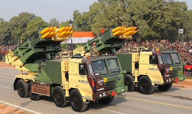 At it's best capacity all 12 rockets can be fired within 44 seconds. The entire operation of coming in laying the launcher, firing and scooting out can be performed in less than 3 minutes. The launcher itself does not need servicing upto 5 missions and is operated by a four member crew. The mobile launcher and a ring laser gyroscope based inertial navigation system for land navigation. The gyroscopes also assist the servo drive mechanism that positions the rockets for firing. The combined power from vehicles power pack and an onboard generator is used as primary power supply for operations of the launcher. Replenishment Facilities LCRV and RV.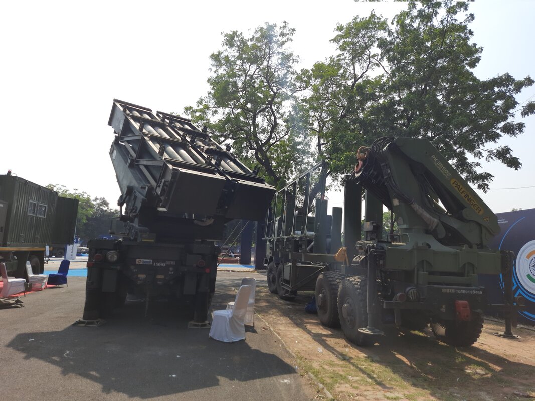 Pinaka Loader Cumbria Replenishment Vehicle and Pinaka Launcher at DefExpo 2022 Once having run out of rockets the launcher can be quickly reused. To facilitate this the replenishment vehicles come into play. These vehicles were developed in association with VRDE. The Loader Cum Replenishment Vehicle LCRV has a crane of lifting capacity of 3.5 tons and carries four pods. The replenishment vehicle RV doesn't have a crane but has collapsible side walkways to let the crew move around while handling the rocket pods. Once the launcher runs out of rockets the expended pods are quickly replaced with new ones. This allows quick rearming and resuming an attack. 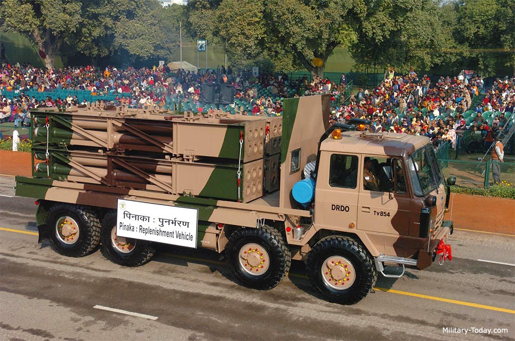 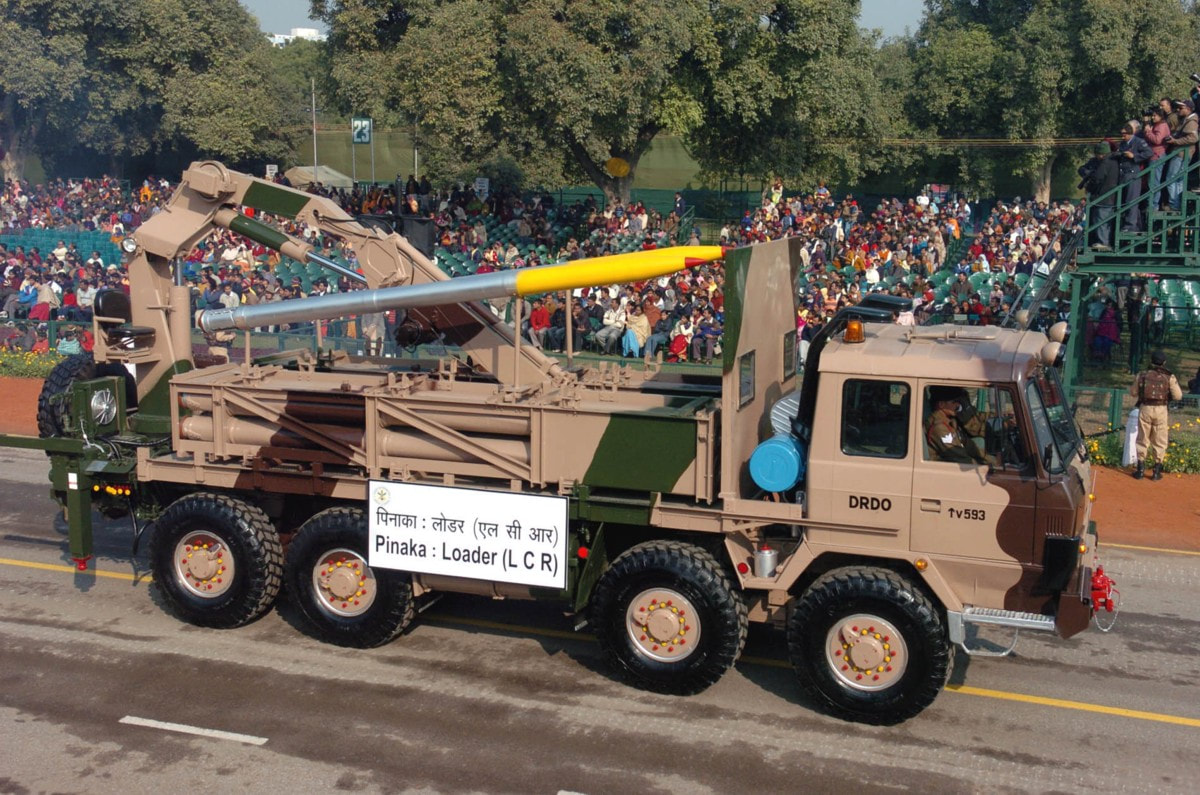 DIGICORA MET radar.The Metrological radar obtained from DIGICORA has been adopted for the Pinaka system. This type of radar is called radiosonde. They are battery powered sensors mounted on a balloon and released in atmosphere to collect meteorological data like wind speed and wind direction. This data is used by battery command post to formulate the right trajectory for firing of rockets. The wind speed and direction would affect the flight of rocket veering it away from target. The data from MET radar helps in planning. Battery Command Post.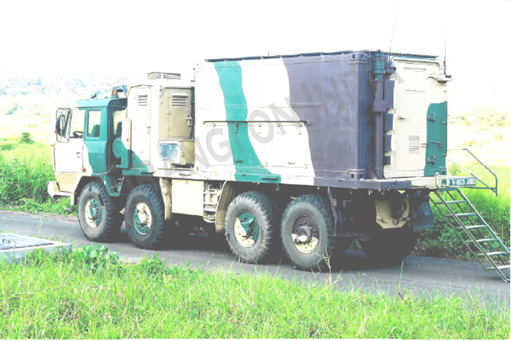 One battery consists of six launchers. All these are controlled and commanded by the BCP. The BCP directs the launchers into to set trajectory and fire when necessary. The BCP has tactical computers communication equipment and are air conditioned. They are equipped with NBC air ventilation system and have shielding against EMI/EMC (electromagnetic interference/electromagnetic compatibility). Through the tactical computers and comms, the commanders sitting in BCP are in constant communication with higher commanders via the Shakti ACCCS network. The main functions are collection of information about target location, live position of friendly launchers. Collection of meteorological data, computation of trajectory and planning for firing sequence. Most important function is to command and control the launchers. Rocket Development Overview.Indian Army have a total requirement of 22 regiments and 1.89 lakh rockets. The Pinaka mk1 soon after completion of development in the 90s saw action during Operation Vijay of Kargil War. Even DRDO personnel went on warfront. The mk1 demonstrated a maximum range of around 40km and has been successfully inducted into forces. Continuing the iterative development Pinaka mk2 has been developed having improved range and being comparable with launchers and other ground systems already in place. The mk2 uses improved propulsion systems, six flat fins instead of four curved WAF fins and other contemporary technologies. The mk2 development also gave birth to mk1 enhanced which has a range of 45+ kms. This development is also under progress. The critical project goals achieved by this development program are developing an industrial ecosystem comprising of different DRDO labs, OFB and private companies. Also other achieved critical goals are as follows. 1 Family of Warheads for rockets. 2 Different types of Fuzes and detonators. 3 Technology and understanding behind Wrap Around Fins. 4 The submunition bomblets and their small fuzes. 5 Ignition systems for solid propellants. 6 High energy materials as solid propellants. 7 Softwares for trajectory computation. THE PINAKA IS A WORLD CLASS ROCKET SYSTEM DEVELOPED INDIGENOUSLY BY THE PAINSTAKING, CONSISTENT EFFORTS TAKEN BY SCIENTISTS AND PRIVATE INDUSTRY PARTNERS.  Pinaka Mk2 The Pinaka rockets provide an unmatched conventional superiority to our forces in a tactical battle and is fully compatible with the Cold Start Doctrine. The strike formations required to move fast would have a guaranteed support for massive attack on the enemy within a short time. As well as the holding formations of army will be able to pin down large invading forces. During the sub conventional warfare like situation between India and Pakistan, the development of such a long range artillery provides the capability to strike deep to the terrorist launch pads operated in POK. In the mountainous warfare, where Artillery plays a vital role, Pinaka provides a shoot and Scoot capability guaranteeing large damages to invading columns. This amazing system developed by DRDO is an example of how indegeneous systems empower a country to achieve self reliance. The economic benefits of which are also massive as just 55 crore rupees of investment has returned almost 61,000 crore rupees. Plus it developed private vendors and created jobs. We wish Pinaka system to be aggressively pitched for exports. WE CREATE TOP CLASS CONTENT SPARING TIME FROM OUR PERSONAL LIVES. IT IS DIFFICULT TO MAKE SUCH CONTENT AS IT INVOLVES A LOT OF BACKGROUND RESEARCH.WE WILL CONTINUE TO DO SO FOR A FORSEEABLE FUTURE AS WE ARE PLANNING TO BUY OUR OWN WEBSITE DOMAIN. IT IS ABSOLUTELY IMPORTANT THAT WE SHOULD REMAIN FINANCIALLY STRONG TO BRING SUCH CONTENT. WE REQUEST READERS TO CONTRIBUTE SOME AMOUNT FOR OUR CAUSE. |
AuthorPalash Choudhari
Categories |
 RSS Feed
