 We all are seeing pretty detailed explanation of the science payload of Chandrayaan 3 and the scientific activities that will be performed on Moon. We have till now seen the detailed explanation of the gravity assist orbit raising maneuvers performed by the Chandrayaan 3 orbiter to get the lander to the moon. We have been closely following the path as CH-3 is approaching the moon. But how exactly the lander works? How exactly it finds it's location with respect to it's surroundings? How does the lander controls it's orientation? How is it going to find i's way to the landing spot? We know we control our vehicles through our steering wheels and see the surrounding through our eyes while we drive. We know that we have a control strick to maneuver an aircraft in the air, but how does a spacecraft controls it's motion? This article attempts to explain in details the sensors on CH-3 lander that are dedicated for spacecraft navigation and control and the functioning behind them. The sensors on CH-3 lander are shown in the images below.    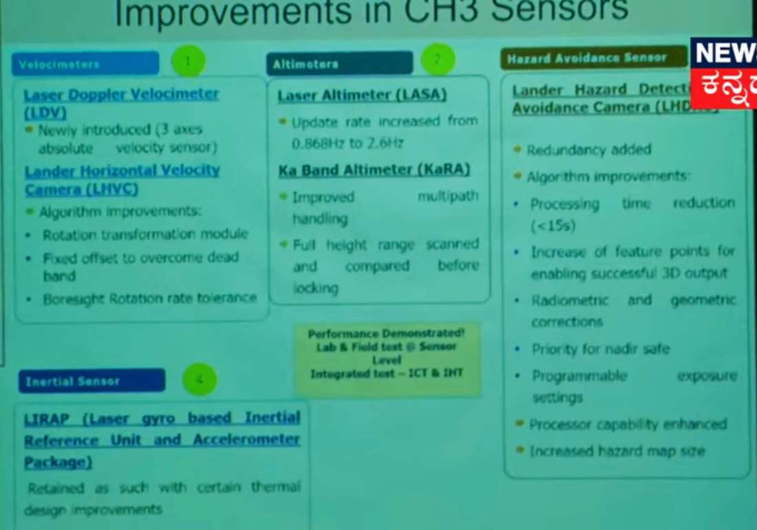 1. REACTION WHEELS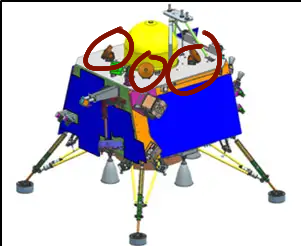 Reaction Wheels as the name suggests are wheels that generate a reaction torque and help change the orientation of spacecraft. Reaction wheels are used to control the orientation of a satellite without the use of thrusters, which reduces the mass of needed fuel for reaction thrusters. They work by equipping the spacecraft with an electric motor attached to a flywheel, which, when its rotation speed is changed, causes the spacecraft to begin to counter-rotate proportionately through conservation of angular momentum. Reaction wheels can rotate a spacecraft only around its center of mass; they are not capable of moving the spacecraft from one place to another. Let me try my absolute best to make you understand this. We all have learned Newton's 3rd law of motion, to every action their is an equal and opposite reaction. The thing that we call Force in linear motion, the same thing is called Torque in circular motion. And Newton's 3rd law when applied in context of circular motion would be like to every rotation their is an equal and opposite rotation. When we move a reaction wheel in zero gravity environment it forces the satellite body to rotate in an opposite direction. Since their are 3 axes of rotation we need motors to rotate reaction wheels that control rotation in all 3 axes. Sometimes two adjacent wheels that are 90deg are rotated simultaneously so that the resultant rotation of a spacecraft happens around an axis that is 45deg to those wheel's axis. This is shown in the video below. I am putting a lot of videos at the end of this pargraph to make you understand how it works. It is hard to understand since we hardly notice it in our day to day lives. But reaction wheels are nowadays a standard part of every spacecraft and it is the least discussed technological Marvel in space technology in my opinion. Chandrayaan 3's lander has 4 reaction wheels at the location shown below. The Vikram lander of Chandrayaan 2 also had them at the exact same spot. The reaction wheels have a max 10 Nms angular momentum and can generate 0.1 Nm Torque for comparison we need 1.7 to 2.2 Nm Torque to open a water bottle. This can give you an idea about the level of precision that goes into making the reaction wheels. Reaction wheels have famously been used in Hubble space telescopes to increase it's pointing accuracy. The lander can thus make very minute, precise corrections in it's orientation while approaching the moon. 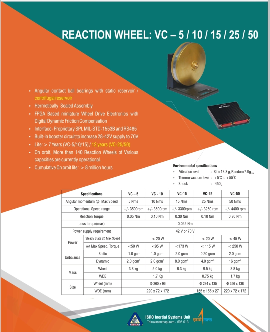 The Reaction wheels of ISRO satellites are made by ISRO inertial systems unit and their is a wide variety of reaction wheels ranging to different angular momentum and torque are available.\u0000 2. LIRAP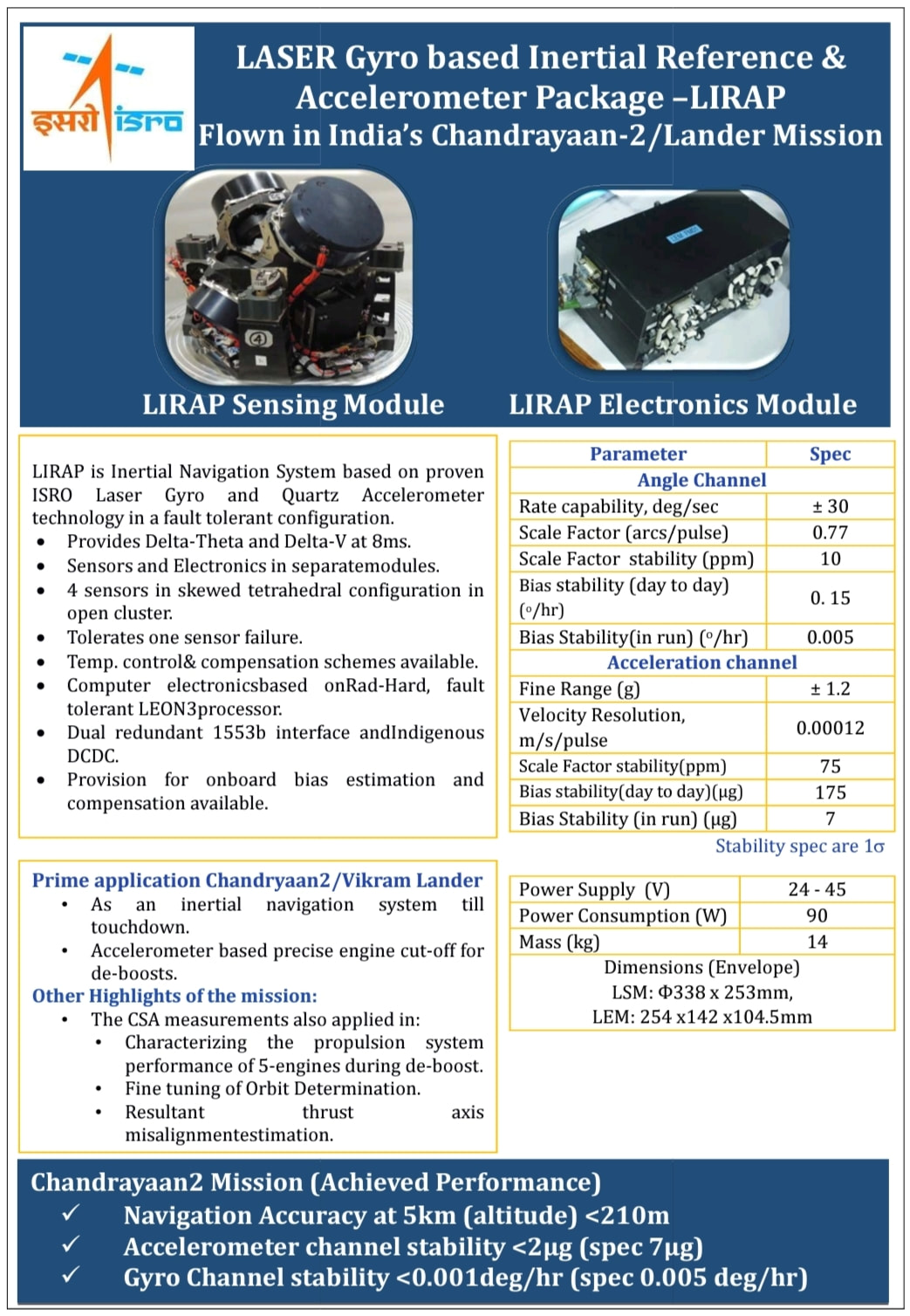 Rover Deployment Sequence.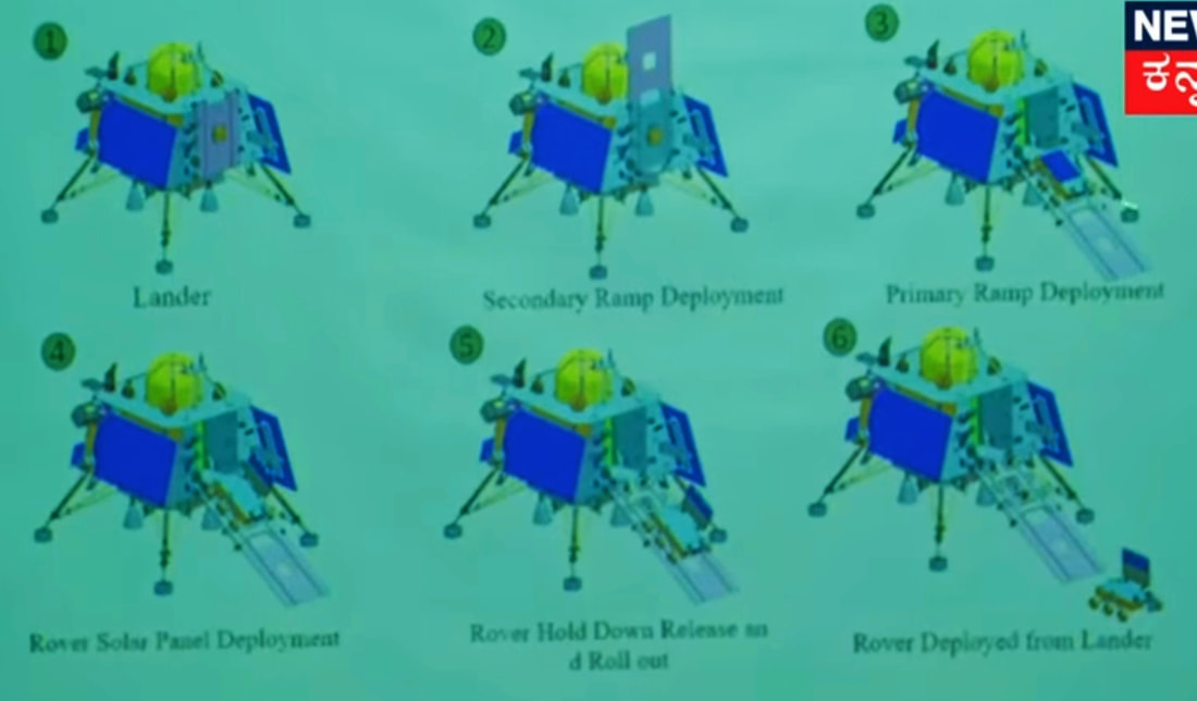 After checking health of all the science payloads and the rover one by one the payload will be activated. Solar Array will activate all vital functions. At around 2015 IST the rover ramp will be deployed. At 2045 IST Rover is switched on and at 2125 IST Rover deploys it's solar panels. At 2140 IST Rover rollout begins. At 2150 IST Rover touches regolith. At 2205 IST Rover takes pictures of the lander. Wishing successful landings to Chandrayaan 3 Source - Chandrayaan-3: 'Vikram' Landing Attempt Updates and Discussion. https://www.reddit.com/r/ISRO/comments/15waz81/chandrayaan3_vikram_landing_attempt_updates_and/ https://www.isro.gov.in/chandrayaan3_gallery.html https://www.isro.gov.in/Chandrayaan3_New.html 5. Laser Altimeter (LASA)A typical laser altimeter determines the range between the instrument and laser footprint by measuring round trip time of laser pulse. The return pulse reflected from surface is gathered by the receiver of laser altimeter, the pulsewidth and amplitude of which are changeable with the variability of the ground relief. 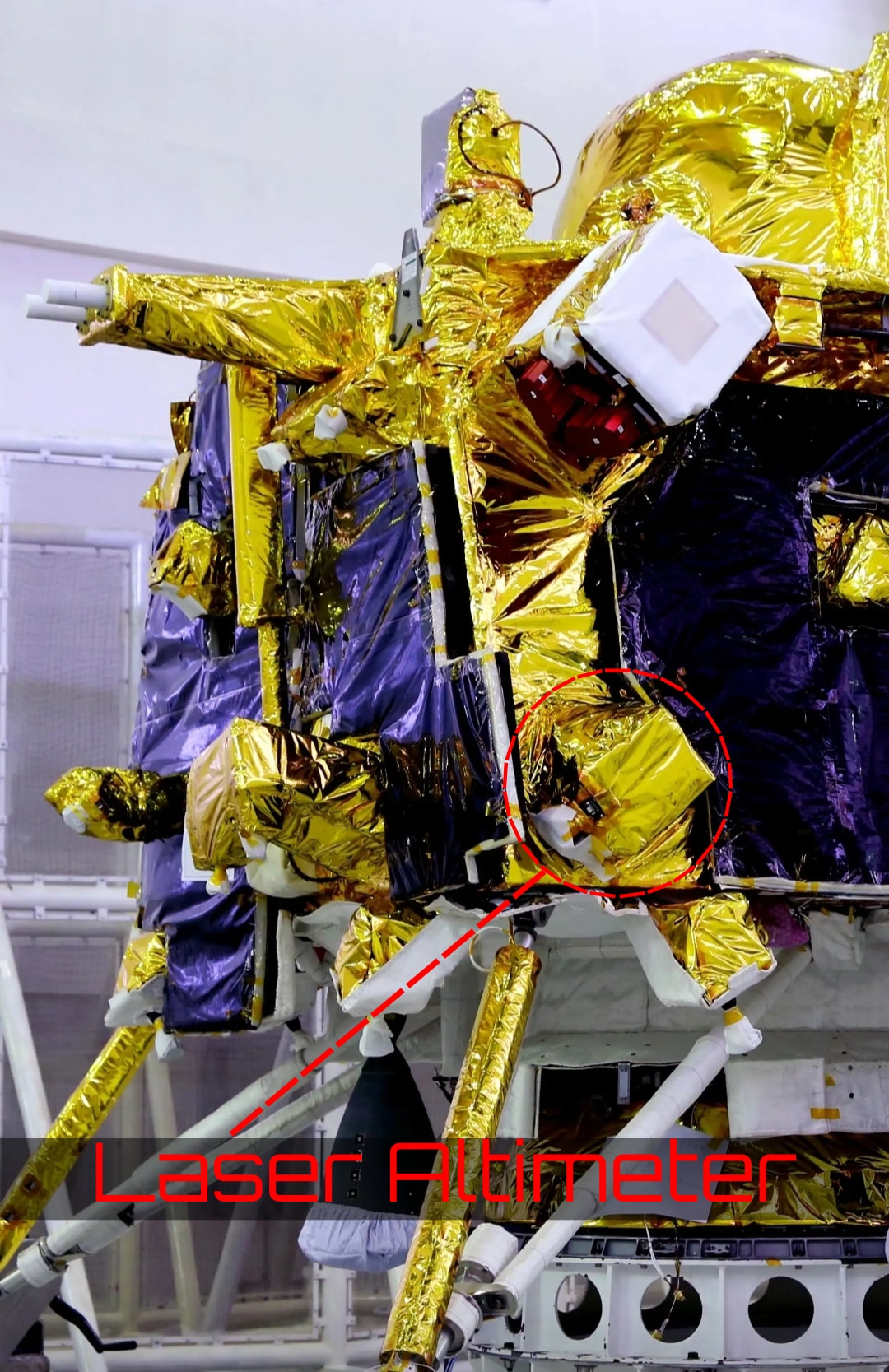 Few years ago DRDO LASTEC helped develop a Laser Altimeter. I suspect it was for Chandrayaan. https://www.drdo.gov.in/diode-pumped-ndyag-laser-space-based-altimeter 6. Laser Doppler Velocimeter (LDV)Need to understand Doppler effect before understanding this device. Do you remember hearing the sound of a siren made by a passing train. Kindly recall that sound in your memory or quickly see a YouTube video. The sound of siren is more when train is approaching you while the sound of siren is less when it is going away from you. You will know if you have observed correctly. This phenomenon is called Doppler effect. We also use some knowledge of constructive and destructive interference and fringe pattern to do something called "optical interferometery" just look at the gooddamn wordplay here. Interferometery means measuring distances using interference and nothing else. 7. Lander Horizontal Velocity Camera (LHVC)This camera constantly takes pictures of the landing sites and compares pictures of the lunar surface features with previous ones. An algorithm is developed to estimate the relative horizontal velocity using the complete camera perspective projection model The images can be used to estimate the horizontal velocity of a lander during the descent phase. This can be used to update the velocities computed by Inertial Navigation System which is based on Accelerometer/Gyro outputs. Since inertial systems measurements of instantaneous velocities are inaccurate due to drift bias and laser Doppler velocity sensor takes too much power the LHVC has been developed. 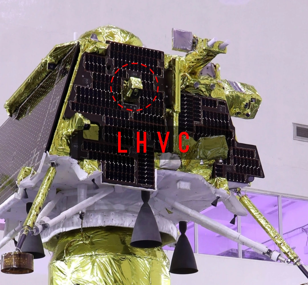 https://www.researchgate.net/publication/338649784_Image_based_Horizontal_Velocity_Estimation_Algorithm_for_the_Descent_phase_of_an_Interplanetary_Lander 8. Micro Star sensor.A preloaded Map of Night sky and position of stars at a particular time is used and the star sensor spots the stars and compares it's position with the preloaded map. This helps identify the position of the sensor. The star sensor is a complex machine that performs various functions in it's processing unit to estimate the position and orientation of a spacecraft with respect to a reference star. This sensor first estimates the centres of stars and then indentifies the stars followed by estimation of attitude (orientation with respected to reference). The data provided by star sensor helps CH-3 lander compare measurements taken by other sensors with some reference to validate the correctness of it's path. I have provided links for further reading. Detailed reading would make one understand the complexity involved in this scientific feat. I am giving some links below for further reading. 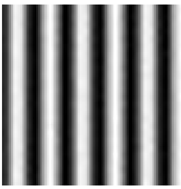 Fringe Pattern 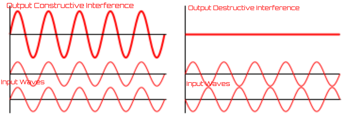 Further Reading https://www.researchgate.net/publication/315667278_Design_and_Finite_Element_Analysis_of_Mini_Star_Tracker www.reddit.com/r/ISRO/comments/dd482a/details_on_isro_built_multihead_star_sensor_under/&ved=2ahUKEwiF7vCnzO6AAxXc_rsIHUXmASg4ChAWegQIBBAB&usg=AOvVaw0Qavgo5MaRL6kn6yp3NRbD 9. Inclinometer & Touchdown sensorsThe LEOS ( Laboratory for electro optic sensors) had developed an MEMS based inclinometer long back ago. The inclinometer has technological commonality with ILSA sensor on CH-3 lander. The MEMS (Micro Electro Mechanical System) based sensor has a proof mass attached to a flexible material, on the other side the flexible material is rigidly attached to a fixed surface. The mass dielectric material attached to it placed in between two charged plates. When the Mass moves the dielectric moves and changes capacitance in between the two charged plates. This change in capacitance corresponds to the physical movement of Proof Mass. ( You need to learn what's a capacitor before understanding this) 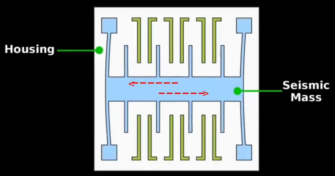 The seismic sensor on Lander works similarly but measures moonquaqes instead of inclination. I suspect their is an inclinometer on the rover as well. I tried my level best to find info on the functioning of the Touchdown sensor but could hardly find any. The Touchdown sensor is designed to detect contact between regolith and landing leg pads. Their are more than one ways to detect and initiate a shut down signal closing off all thrusters. It's really hard to make a guess. Landing Sequence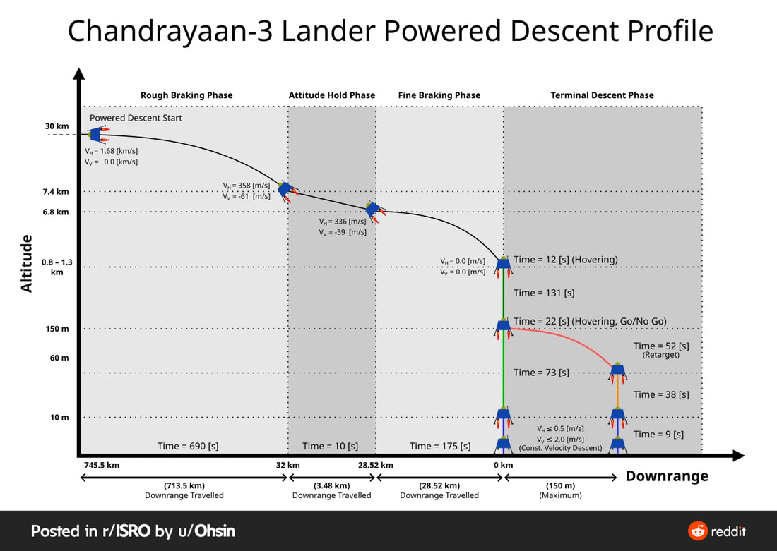 2 Hours prior to landing a poll will be conducted based on health of lander and landing site conditions the poll will result in a "Go" or "No-Go" decision. If the decision ends in No-Go then landing attempt will be shifted to 27th August 2023. ISRO cheif even said that if conditions not met then they may postpone the landing attempt to September. Unlike previous attempt this time we have high resolution images of the potential landing sites taken by Chandrayaan 2. At 1745 IST / 1215 UTC powered decent will begin and all 4 engines will be fired for 11 Min 30 Sec. The rough breaking phase will end here and a 10 second long altitude holding phase will be initiated, lander will begin tilting at ~50° lander expected to decent upto 6.8 km altitude during these 10 seconds. At 1756 IST Fine braking phase begins and two engines out of 4 engines are shut off. The phase will last 2 min 55 sec. Lander drops to the altitude 0.8 - 1.3 km. At 1759 IST Lander hovers for 12 seconds to survey the landing site and instruments callibrate during this time. At 1800 IST (approx) Lander begins verticle decent that will last 2 min 11 seconds. Lander drops down to an altitude of 150m. At 1803 IST Lander will hover for 22 seconds to detect potential hazards like boulders and big sized rocks and make a Go-NoGo decision to land or not. If a Go decision is taken then lander decends to 10m altitude at 1805 IST (approx) and initiates landing at a decent rate of 1m/sec. Which means at 1815 (approx) the lander will touch down the regolith. If a No-Go decision is taken lander will select an alternate landing spot 150m away from main spot and decent to 60m altitude above altenate landing spot at 1803 IST and decent down to 10m altitude at 1804 IST. It will begin landing at a decent rate of 1m/sex and touch down at 1814 (approx). The Touchdown sensors will confirm contact with regolith and shut down all thrusters. Even if communication with CH-3 orbiter fails the lander has an X Band antenna to directly communicate with earth confirming it's status. 4. Lander Position Detection Camera (LPDC) LHDAC (Lander Hazard Detection & Avoidance Camera)These features were added later on CH-3 lander and are going to enhance overall survivability. The functions are simple to understand from the names themselves. I am putting photos of potential locations of these cameras. These cameras are sidelined amongst other sensors but they will get a major role incase CH-3 lander decides to select an alternate landing spot. This feature is a major difference between CH-3 lander and Vikram. It will be exciting to see pictures of around the moon from these cameras. 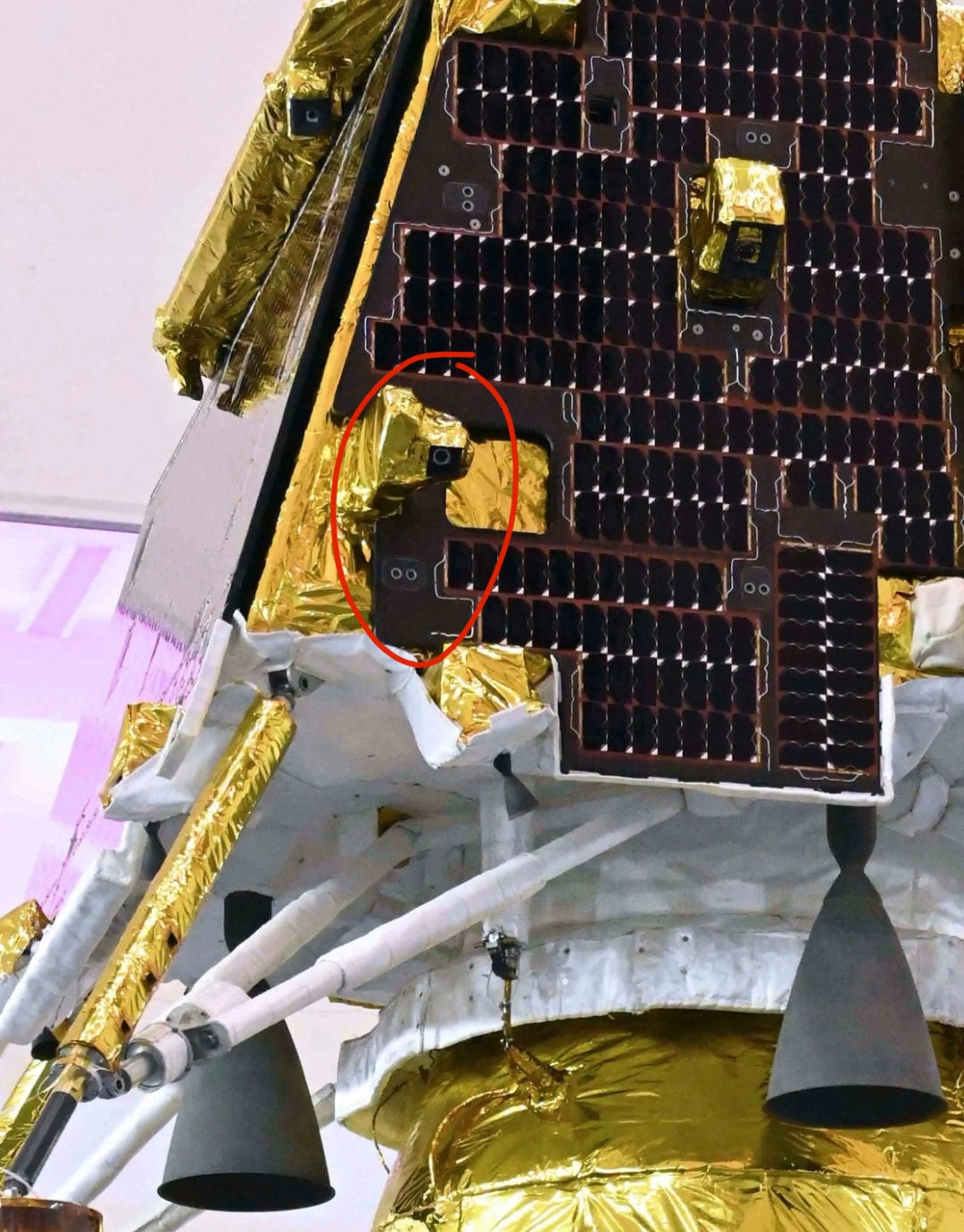 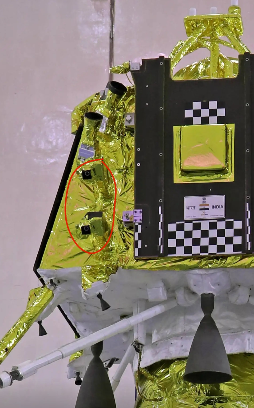 3. Ka-Band Altimeter (KaRA)This is a simple radio frequency based sensor used for measuring altitude constantly. The radar works by sending a focussed wave towards a target an then recieving the wave after some time. Based on the time taken between sent wave and received wave the distance between object and target is calculated using the old school speed = distance / time. Since radio frequency waves are fast it helps calculate the distance between CH-3 lander and lunar surface very fast. This sensor may be for redundancy purpose because their is a laser based sensor exactly for altitude measuring purpose. 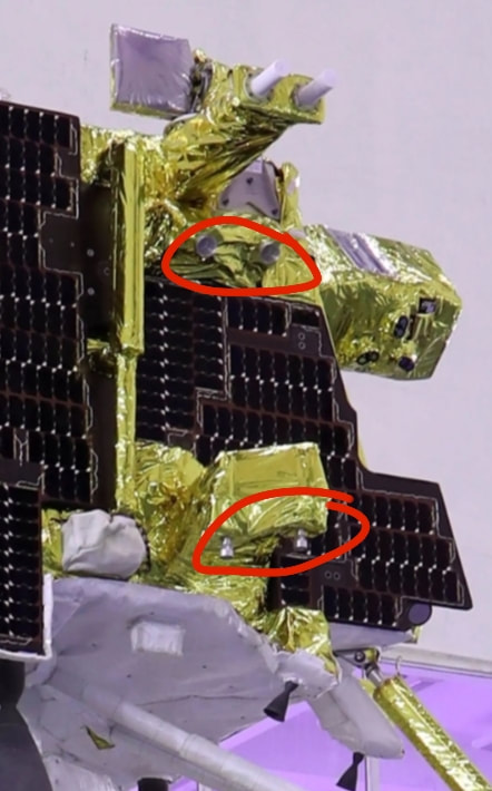 The Ka-band radar altimeter (KaRA) system attached to the Vikram lander will activate 7.5 km above the lunar surface and send the necessary inputs to the ISRO headquarters. The processors of the hazard detector camera and KaRA were designed by Ahmedabad's ISRO centre. 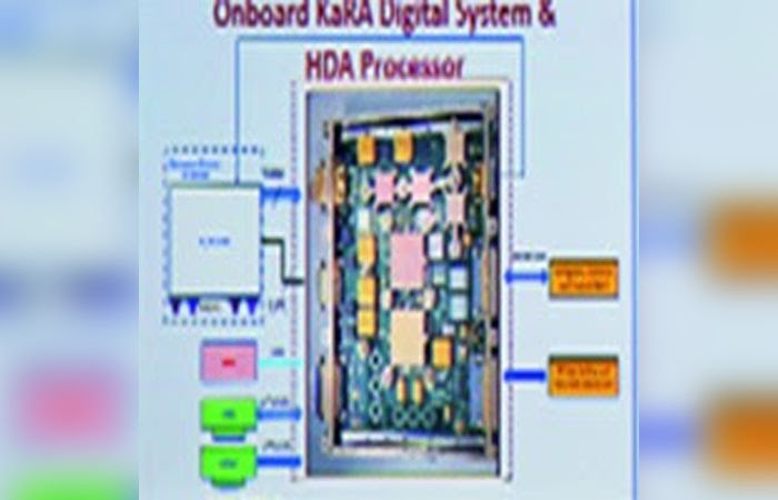 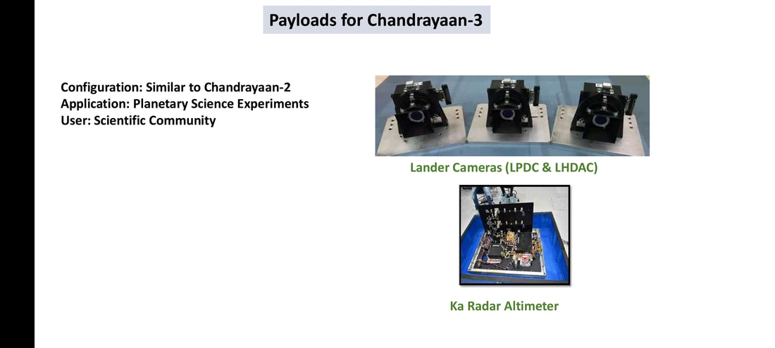 Chandrayaan 3's lander has 4 reaction wheels at the location shown below. The Vikram lander of Chandrayaan 2 also had them at the exact same spot. The reaction wheels have a max 10 Nms angular momentum and can generate 0.1 Nm Torque for comparison we need 1.7 to 2.2 Nm Torque to open a water bottle. This can give you an idea about the level of precision that goes into making the reaction wheels. Reaction wheels have famously been used in Hubble space telescopes to increase it's pointing accuracy. The lander can thus make very minute, precise corrections in it's orientation while approaching the moon. The Reaction wheels of ISRO satellites are made by ISRO inertial systems unit and their is a wide variety of reaction wheels ranging to different angular momentum and torque are available.\u0000 I am putting a lot of videos at the end of this paragraph to make you understand how it works. It is hard to understand since we hardly notice it in our day to day lives. But reaction wheels are nowadays a standard part of every spacecraft and it is the least discussed technological Marvel in space technology in my opinion. Sometimes two adjacent wheels that are 90deg are rotated simultaneously so that the resultant rotation of a spacecraft happens around an axis that is 45deg to those wheel's axis. This is shown in the video below. 1. Reaction Wheels PSLV is not immortal as said by ISRO Chief Dr. S Somnath. PSLV was designed in 80s and cannot serve requirements of 2020s. After completing the government approved missions PSLV will be retired. Dr. S Somnath spoke these above words at “Engineers conclave 2022” at LPSC, Tirvananthapuram. The propellant used in some stages are toxic, the manufacturing processes of some components are too tedious to be scaled up and with new advancements in space technologies elsewhere, people can launch payloads in space more efficiently and at a cheaper costs. In an industry where the sizes of satellites and launch vehicles are getting smaller PSLV worked as workhorse but would soon be outdated by the quick “launch on demand” type Launch vehicles being developed by startups. Clearly ISRO has made SSLV for that and for high capacity govt, military and exploration satellites ISRO is developing a new modular launch vehicles that takes some inspiration from Spacex and some innovation from their own skills. Few years back ISRO presented a concept named ULV (unified launch vehicle) which showed multiple variants of GSLV mk3 like Launch Vehicle, I even made an article about it. The NGLV takes the same modularity approach so that standardised systems and subsystems could be manufactured en-masse and stored to keep the Launch Vehicles ready. standardised common parts amongst various systems and stages could mean more volume of order of these parts that should bring down procurement costs. 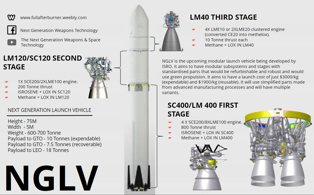 ISRO scientists took painstaking efforts to make upper stage cryogenic engine of GSLV mk2, the case of Shri Nambi Narayan is infront of us already. These efforts led to development of CUS/CE20 engine that is used in GSLV mk3 today and is being uprated currently. Despite all this time has come to replace these launch vehicles for good so that we could become an advanced level space power from an entry level position that we are at right now. We have compiled information scattered on internet here and there to give a general idea about the technological development happening for NGLV. Unlike ULV many technologies are currently being developed in that pursuance. Since the future is unpredictable any future disruptive technology might put the NGLV concept in doldrums just like ULV. ULV terminology itself is outdated now. BASIC CONFIGURATION 3 stage and 2 stage modularOut of all the presentations given by Dr. S Somnath the previous designs were all 3 stage and talked about expendable Super Heavy Launch Vehicle. But in one of the presentations a two stage variant was seen. This two stage variant was seen with just SC400/LM400 as first stage and LM40 as second stage. For NGLV claims are being made for carrying 10 Tonnes to GTO which make it the first heavy class SLV being made in India. It also has bold plans to bring launch cost to LEO at just 1900USD/kg. This configuration shows from what I understand an optional second stage that could be used only for heavier payloads. The upper stage is all methelox while first two stages have optional kerelox or methelox propulsion systems. Contrary to the outside appearance I expect the methelox and kerelox stages to be completely different. They would also need different volumes of fuel and oxidiser which would influence the fuel tank sizing. In an ISRO RTI reply it was revealed that the SCE200 engine which will be clustered to form the core SC400 stage is not restartable hence not reusable. This means that ISRO will use methelox based propulsion systems on expendable stages and kerelox based systems on recoverable booster stage. I personally think NGLV when and if made will look quite different from what is being shown in presentations. This entire article is our speculation from a space enthusiast point of view. 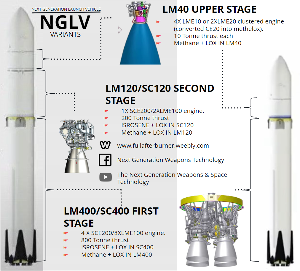 RLV A DIFFERENT VERTICLE THAN NGLVISRO is still pursuing development of RLV. Technologies are being tested, mentions are done in presentations and press conferences. Their are three configurations of RLV, one is where first stage is VTVL recoverable booster plus winged second stage. Second is winged first stage with parachute recoverable upper stage and third is that whacky spaceplane first stage and RLV second stage. I putting pictures below for reference all are taken from presentations. Very recently LEX was performed with a model RLV dropped from a helicopter. In next test they will send an RLV model in space from atop a GSLV mk2 and attempt de orbit and landing. I personally wish this test should use the ADMIRE test vehicle instead of GSLV mk2 I don’t know weather ADMIRE could impart enough delta V to a standard sized RLV model or not but it would look like a 100 percent reusable launch vehicle. TSTO with RLV upper stage can be seen in this snapshot from a presentation slide below. We have hypothesised that SC400 is not recoverable so this configuration might only be for test purpose. 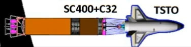 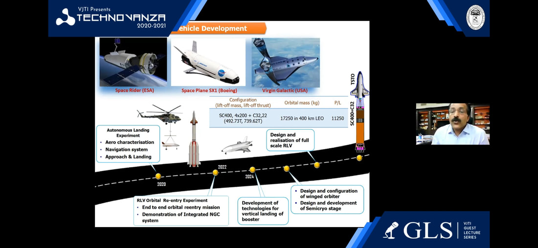 There is also another configuration of the same vehicle. Here they planned to use RLV as first stage and parachute recoverable second stage. The entire concept can be seen in the video below. Pegasus RLV videoPROBLEMS WITH RLVThe RLV as a space shuttle inspired vehicle seems good as concept. It is not absolutely reusable like an aircraft but it is refurbishable. But the limitations are also similar tp space shuttle. The RLV aims to bring down the cost required to build a brand new SLV to launch a payload by making the SLV reusable. But unlike other SLVs RLV has wings, it has heat resistant tiles and an engine that would barely have any use in space. For the same amount of fuel spent a normal SLV can carry larger payload compared to RLV, because RLV has to bear extra weight of the wings and tiles, etc while launching. Space Shuttle faced this same problem. Instead of brining costs down it actually increased the costs. The Soviets cancelled Buran exactly for this reason. With technological advancements that happened during development of Spacex falcon 9 and starship after retirement of space shuttle, refurbishment has actually become simpler. Inclusion of new technologies might bring refurbishment cost and complexity to a level where launch cost per kg would be competitive. The RLV can be used for a military application. We will surely find out in future let’s focus on NGLV for now. Watch this video for points discussed on RLV. CURRENT DEVELOPMENTS.100 tonne Methelox engine clustered to form LM400 stage.100 tonne methelox engine is being pursued by ISRO as confirmed by Dr. S Somnath in a presentation and an RTI response by ISRO. 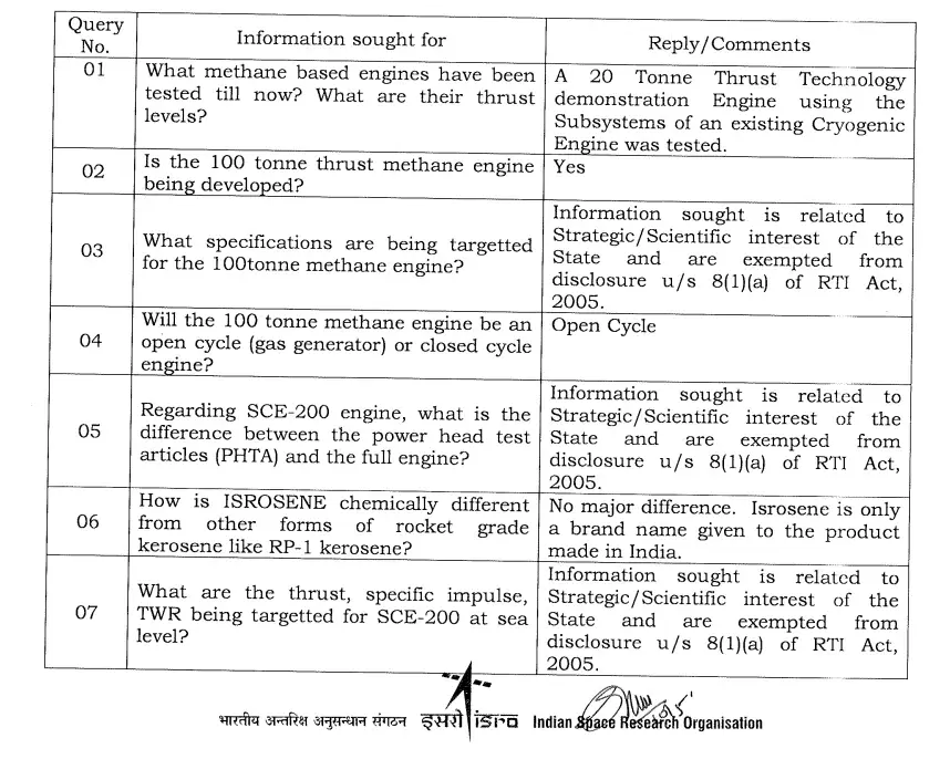 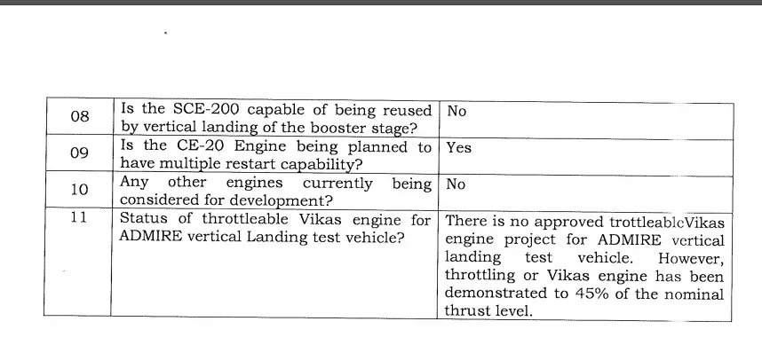 An RTI filed by some space enthusiasts responded that the 100KN metheox engine being developed by ISRO is throttleable and reusable. ISRO presentations by Dr S Somnath has shown first stage of NGLV have “LM400” engine. All these things hint at the methelox engine being clustered and used in LM400. The SC400 will be used in expendable NGLV I guess. The same RTI replied that SCE200 isn’t reusable. A news article appeared in a local TV news channel about ISRO’s development of 100 KN LOX Methane engine. Single SCE-200 used to form SC-120 stage. This development is being pursued for GSLV itself. The L110 core stage will be replaced by SC120 and the CUS/C-25 upper stage will be modified into C-32 stage having a higher propellant loading. The C-32 will also be restartable. This feature helps in achieving the Delta V in an economical way by coasting the upper stage for some time. ISRO also plans to use advanced composite materials, miniaturised avionics and iso-grid structures in interstages for weight reduction. As per presentation slides the payload capacity of LVM3 would dramatically increase upto 5.5 to 6 tonnes in GTO, just imagine what could be the capacity for LEO I wish it could go upto 20 tonnes in LEO. In some old presentations about HLV a GSLV mk3 uprated version is seen SC200 core stage with 2 S250 boosters and C-34 upper stage having a whopping 28 tonnes payload capacity to LEO.  Conversion of CUS/C25 stage into a methelox engine clustered to form LM40 stage.I found this slide in an old presentation last year which talked about a 5 to 10 tonne thrust Methelox engine. The slide clearly used words like “restarting abiltiy” and “throttling capability” showing prospects of reusability. Since CE20 produces around 20 tonnes of thrust I think they will have to cluster two such engine to produce equivalent thrust. 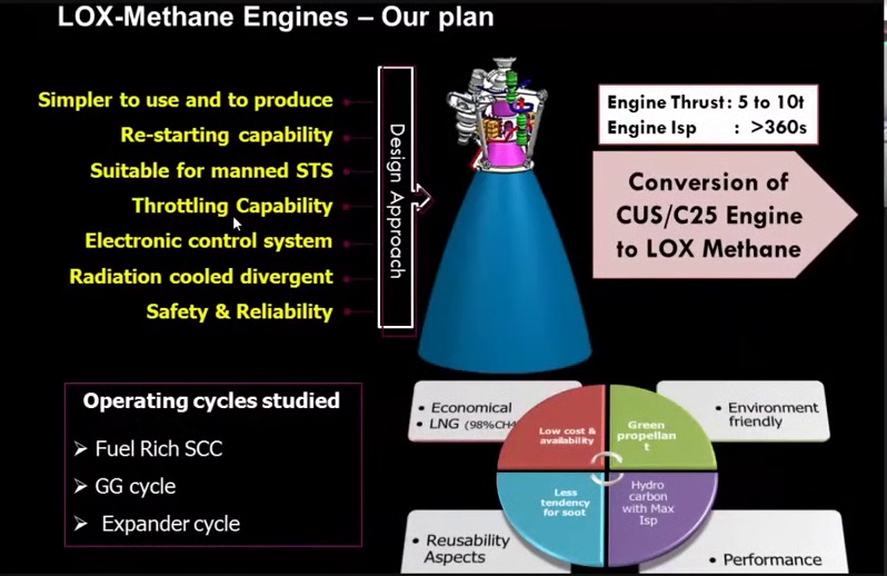 LM20 Methelox engine clustered to form LM40 stage.Last year ISRO conducted a hot test of 20 tonne thrust engine. The engine said to use similar gas generator cycle that is used in CE20. As per the same slide, ISRO is trying it’s hands on Fuel Rich Staged Combustion Cycle or an Expander-Bleeder cycle in the upper stage methelox engine development. LM20 Methelox upper stage engine hot test. Interview of LPSC Director Dr. V Narayanan, watch from 10.00 He mentions LOX Methane engines. Clustered SCE200 to form SC400 stage. Throttleable Vikas Engine Development CLICK ON THE IMAGE TO VIEW TEST NEWS BY ISRO Liquid engines that support throttling of the engine thrust facilitate booster stage recovery in launch vehicles. In order to enable booster stage recovery in future launch vehicle configurations, the first Throttling demonstration hot test of the Vikas engine was successfully accomplished on January 30, 2023 for a targeted 67% thrust level throttling for a duration of 43 s. Throttling of the engine was achieved by a closed loop thrust regulation system and the engine had been successfully throttled from the chamber pressure of 58.5 bar in steps of 50 bar, 45 bar & 40 bar, with dwelling at each pressure level for 7 s. In addition, the Vikas engine was also throttled down to 45% for the last 3 s before the engine shut down. The results of the first hot test of Throttleable Vikas Engine indicate stable combustion and subsystem performed in accordance with the prediction. The overall performance of engine sub-systems, control systems & test facility systems were as expected. ISRO’s strategy for design and development. ISRO if currently focused on achieving fundamental levels of technological capacities like supersonic retro propulsion with deep throttling and restart capability for it’s upcoming VTVL mission. Other developments like Landing gear and grid fins are also going on. Once completed the ADMIRE test vehicle will be used to test the technologies to validate ISRO’s ability to develop a reusable vertical landing Launch vehicle. ISRO is planning to modify the L40H strap on boosters used on GSLV mk2 that produce 760KN of thrust using Vikas engine. Once this development completes ISRO will start development of throttleable 100 Tonne methelox and kerelox engines as well as clustering of 800 tonne engine.  All these technologies will go in making a recoverable SC400/LM400 stage which will be the core stage of all variants of NGLV. For this development Core Booster Recovery Experiments will be performed. The development of engine clustered upper stages will commence afterwards. The new initiatives being undertaken by ISRO is development of miniaturised and weight optimised avionics, advanced light weight composite materials, additive manufacturing and 3D printing of critical components for ease of production, minimal turnaround time and bulk manufacturing. Prospective requirement.The primary objective will be similar to GSLV mk3 which is launch Communication and Earth Observation satellites for Civil and Military purposes. ISRO has plans for deep space missions on Mars, Venus, Moon and Sun. With increase in interest and Govt spending ISRO might attempt an asteroid study mission as well. In some old presentation of Dr. S Somnath a similar looking vehicle using SC400 first stage and C32 second stage was seen, named as HLV-HSP. ISRO will definitely use the NGLV technologies to make a Spacex Falcon 9 type reusable first stage crewed launch vehicle. SInce ISRO has concrete plans to build a space station for permanent Indian orbital human presence the components of Indian Space station and cargo supply missions can also be launched from an NGLV.  ISRO will also launch interplanetary missions in future. Chandrayaan 3 has a payload that detects earthlike exo planets.   Finally, despite the success of one web. If ISRO or some other company decides to launch a large constellation of satellites for earth observation or communication purpose NGLV would be an amazing low cost carrier option. Small is the new big in space industry. The space industry's current trend of going smaller is a result of technological advancements making processors and computers very small and capable of performing complicated tasks which were otherwise performed by bulky processors in past. Advancements in rocket propulsion technology made propellants that are lighter in weight. Throughout the world each and every space technology agency is on a race for making small launch vehicles. Satellites getting small and cheap have prompted many media companies to launch their own small satellites instead of seeking service from a heavy government owned satellite. Because of multiple competitors and heavy competition the prices are low and demand is high.  Small is the new big in space industry. The space industry's current trend of going smaller is a result of technological advancements making processors and computers very small and capable of performing complicated tasks which were otherwise performed by bulky processors in past. Advancements in rocket propulsion technology made propellants that are lighter in weight. Throughout the world each and every space technology agency is on a race for making small launch vehicles. Satellites getting small and cheap have prompted many media companies to launch their own small satellites instead of seeking service from a heavy government owned satellite. Because of multiple competitors and heavy competition the prices are low and demand is high.  ISRO's Antrix Corporation had been able to generate a huge amount of revenue due to the relative cheapness in launch service. Problem however is ISRO’s current availability rate is lower than market's requirement. It takes around a month to build a PSLV or GSLV and also a huge amount of space in payload fairing is reserved for a Satellite from India. Elsewhere due to the availability of knowledge in public domain and lower investment costs Private companies are making foray into space launch services providing an alternative to the monopoly of Government funded space agencies. If these private companies take away the available customers ISRO would not just loose its revenue but also an opportunity to bring technological and commercial capability in India. Being quick and perfect in its efforts ISRO took no time designing a small launch vehicle that would satiate the growing demands of launch service with also providing its service in competitive prices. The prices charged by ISRO are as competitive as some private company.  DESIGNLargely taking it's roots from PSLV's design the SSLV is a 4 stage launch vehicle with fourth stage being a Velocity Trimming stage. Velocity trimming is an interesting concept explained later in this article. The first three stages are largely common with PSLV. Where the first stage is a 3 segment solid booster and 2nd and 3rd stage having solid rocket motors derived from PSLV’s PS3 stage. The whole aim was to quickly design a Launch Vehicle that can be very quickly assembled by a small team and launched by a small team. The SSLV stages will be manufactured in modules totally by Private Industrial partners of ISRO once development is complete. The most interested in this project is L & T. Other companies like MTAR, Godrej Aerospace are major contributors in supplying critical components for both PSLV and GSLV.  The aim is ease of operation and reduction in costs’. Today prices of ISRO's launch services are high due to lower launch rates since a private company cannot be contracted to supply their components in large numbers it is unprofitable for them to supply smaller numbers. Since demand for launch services is high ISRO intends for increased number of launches hence increased orders for private companies which will drastically reduce prices. The ease of operation comes with large autonomy in assembly and launch procedures. Since solid rocket boosters once filled in with propellants can be stored for longer times and quickly assembled in launch ready position. 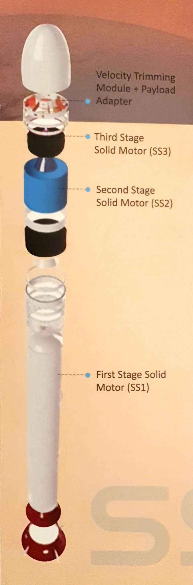 The first developmental launch is taking place from SHAR, but an alternate launch site in Thoothukudi in Tamil Nadu has been selected FIRST STAGE BOOSTERThe solid rocket propellant technology is widely used in India for Missile making purposes and also in initial stages of PSLV and GSLV. The most widely used fuel is HTBP. The first stage called SS1, the S-85 motor of SS1 will have 89 tonnes of propellant mass. The first stage will have 3 segments of motor casing. Since the casing has to be lined with insulation, ISRO has decided to use simple natural rubber based insulation.  A solid propellant rocket motor has a long combustion chamber concentrically filled with solid propellants. Once ignited electrically the propellant burn radially outward. The nozzle has to withstand a large amount of heat with no cooling and hence it is made of materials with high specific heats. In S-85 motor the propellant grain is circular in shape which intends to increase the thrust with respect to time. Please watch the video to understand what is grain and why it's shape matters. 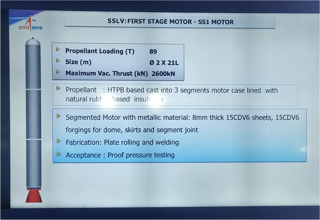 The outer casings are made of 8mm thick sheets made of 15CDV6 sheets rolled into a cylindrical shape and then welded. The top dome is forged from the same material. The skirts and segment joints are also manufactured using the same material. The entire stage is 2 Metres in diameter and 21 Metres in height and would produce 2600 kN of thrust in Vacuum. To understand how solid rocket motor works do watch this amazing video. Electro Mechanical Actuator of first stage.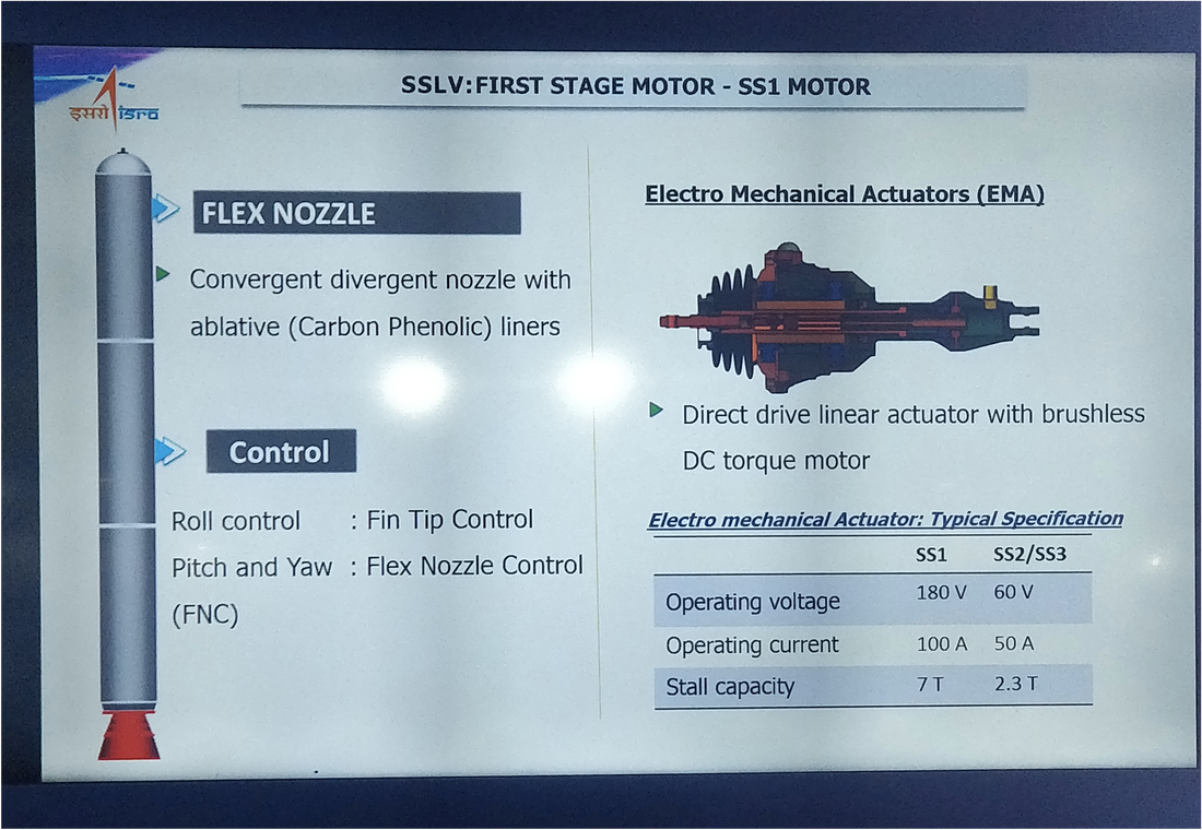 SECOND AND THIRD STAGE SOLID MOTORSThese stages use a unique Solid Booster derived from PSLV’s PS3 stage. The PS3 is of 2 m diameter and 4850 litre capacity. PS3 motor case weighing 325 kg was initially realised by filament winding process using Aramid/Epoxy for the construction for the shell and Carbon/Aramid/Epoxy hybrid construction for the skirt extension. A new improved version called High Performance motor case (HPS3) has been realised for PS3 motor case. An optimum design for this was evolved by selecting appropriate different profiles for both the domes, introducing dome reinforcements and adopting modified helical winding with wide band in multi axis filament winding machine.  The motor case is designed for a maximum operating pressure of 60.8 bar using Aramid/Epoxy for the construction of shell. The motor case consists of helical hoop layers and Aramid fabric for dome reinforcements. Carbon/Aramid/Epoxy hybrid construction for the skirt extension to attach with the fourth stage of PSLV is designed for taking the structural tensile load of 460 kN and a compressive load of 215 kN. A design factor of 1.25 is applied over the flight loads. Aluminium alloy end fittings are provided for the assembly of igniter and nozzle on either side. After rocasin insulation lay-ups, 7500 kg of solid propellant is cast.  Since a huge amount of technical know-how is readily available the SS2 and SS3 stage of SSLV also use the exact same technology. Here also Aluminium alloy is used for end bosses and skirt rings and Nozzle is made up of Carbon phenolic liners and graphite while motor casing is made up of filament case wound with medium strength carbon fibre. Both SS2 and SS3 uses HTBP as propellant. The SS2 uses 7.7 tonnes on propellant has a 2m diameter and 2m length and maximum thrust 250 kN while SS3 uses 4.5 tonnes on propellant has 1.7m and 1.6m as length with maximum thrust of 160 kN. The second and third stages of SSLV thus only have a size difference but technology wise are highly identical. 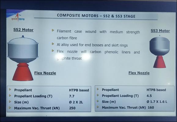 VELOCITY TRIMMING MODULE (COOLEST STAGE)This is the most interesting stage of SSLV and this one will be the only liquid propellant powered stage of the entire SLV. The 4th stage’s main function is to deliver multiple satellites into multiple orbits. ISRO has earlier modified PSLV's PS4 stage in such a way that it could deliver satellites in multiple orbits. In order to achieve multiple orbits, two different options, namely, having separate propulsion module or employing upper stage restart, are available. SSLV has selected the second option-restart of Velocity Trimming Module and having long coasting between two restarts.  EOS-02 being loaded into VTM To launch satellites into multiple orbits the Velocity trimming module is essentially set into orbit itself and performs multiple burns to do roughly the same activity called Orbital Manoeuvre. Even though an orbit is determined by inclination, eccentricity and various other Keplarian elements, The change in orbit is performed by increasing or decreasing ∆V (Delta Vee). This is done by either firing or I should say re-firing the engines of a spacecraft to increase it's ∆V or turning a spacecraft around itself in 180° and then firing spacecraft to decrease it's ∆V. ∆V is the impulse per unit of spacecraft mass that is needed to perform an orbital manoeuvre. 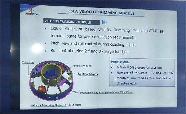 The velocity trimming module’s design derived from PSLV’s upper stage PS4. This 4th stage of SSLV has Propulsion deck along with tankages positioned outside the central cylinder with 4x50N thrusters, also 4 thrusters just below each of the two tankages. This configuration thus has a total 12 Nos. 50N thrusters. PSLV has six of them for attitude control during its coast phase. On top of it there is a satellite adaptor which can hold multiple satellite deployment mechanisms based on launch requirements. Satellites can be stacked around the periphery on a Quadpack. The avionics packages are assembled on a deck peripherally around central cylinder. This configuration can accommodate the satellite protrusions below launch vehicle interface, APD was brought near the mid-section of central cylinder for better accessibility and for CG and MI balancing positioned in the remaining 240Deg. around the central cylinder. All components are sub-assembled as modules and integrated into each other during assembly this is done to reduce waiting time for a critical activity. 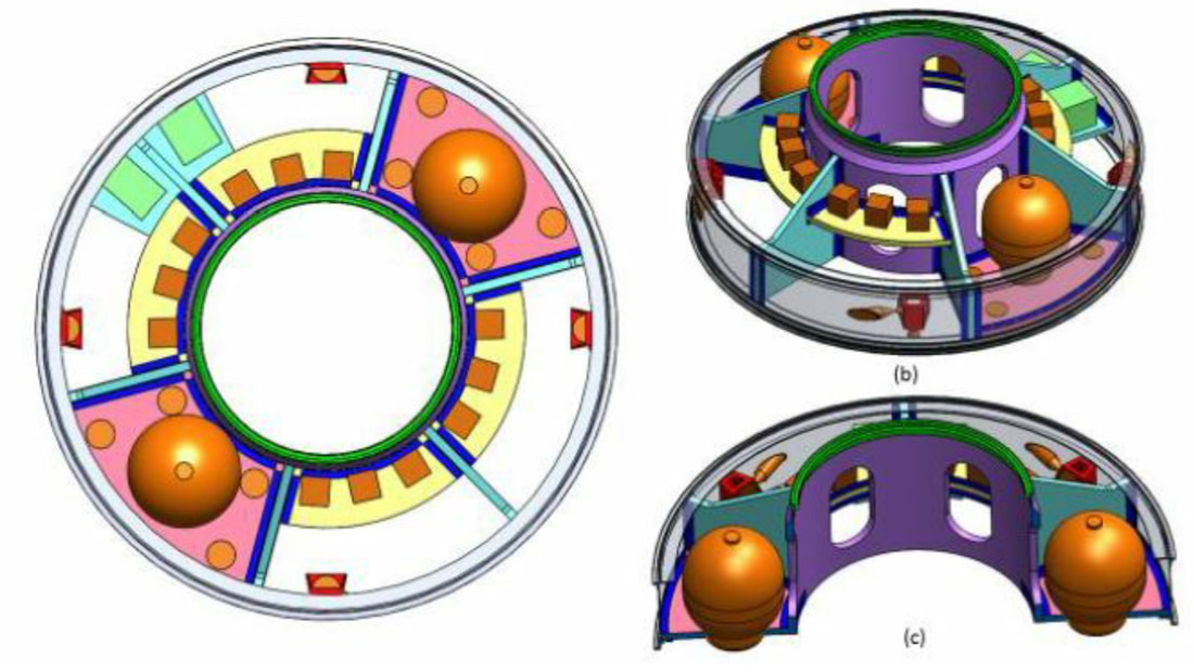 VTM configuration top view showing tankages, thruster blocks, APD, ISP and quad-pack location, (b) Isometric view of module showing tankages, axial, tangential and radial thrusters, (c) cut section view. 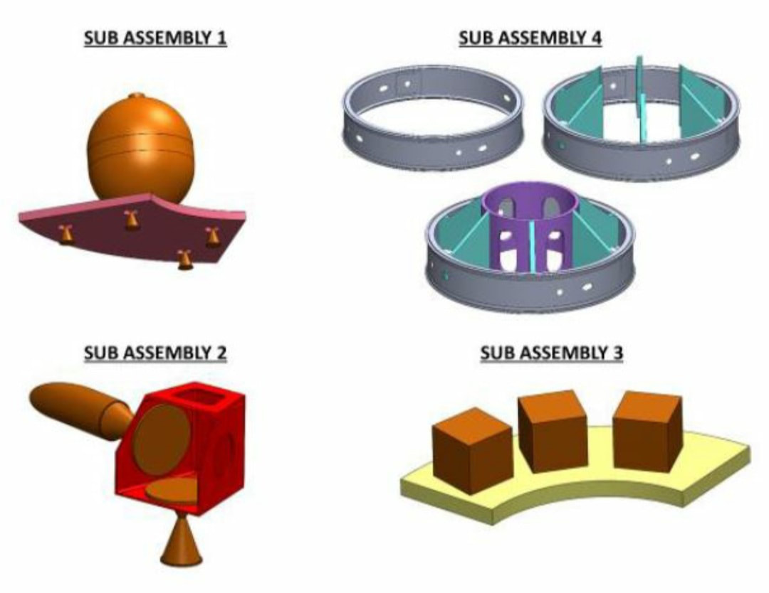 sub-assembly 1: Propulsion deck with 50N thruster 2: thrust block assembly with 50N thruster, sub-assembly 3: avionics package deck 4: structure. mounting system called ISRO Ball Lock or IBL of various sizes is used to stack multiple small satellites circumferentially around it. It uses a Pyro actuated ball lock separation system. This provides a debris free release and very less shock during pushing out a satellite into orbit. SSLV would be using IBL-296 and IBL-230. IBL stands for ISRO Ball Lock and the number stands for the interface diameter in mm. There are several of these IBLs available with ISRO and used on multiple launch vehicles. It is beyond the scope of the article to explain all separation mechanisms in detail but We have provided links here for whoever wanted a further reading. Similarly there are multiple satellite separation systems used in SSLV upper stage. Satellites can be stacked one above other, 3 satellites can be mounted circumferentially and so on. Multiple satellite mounting options are shown in pictures below 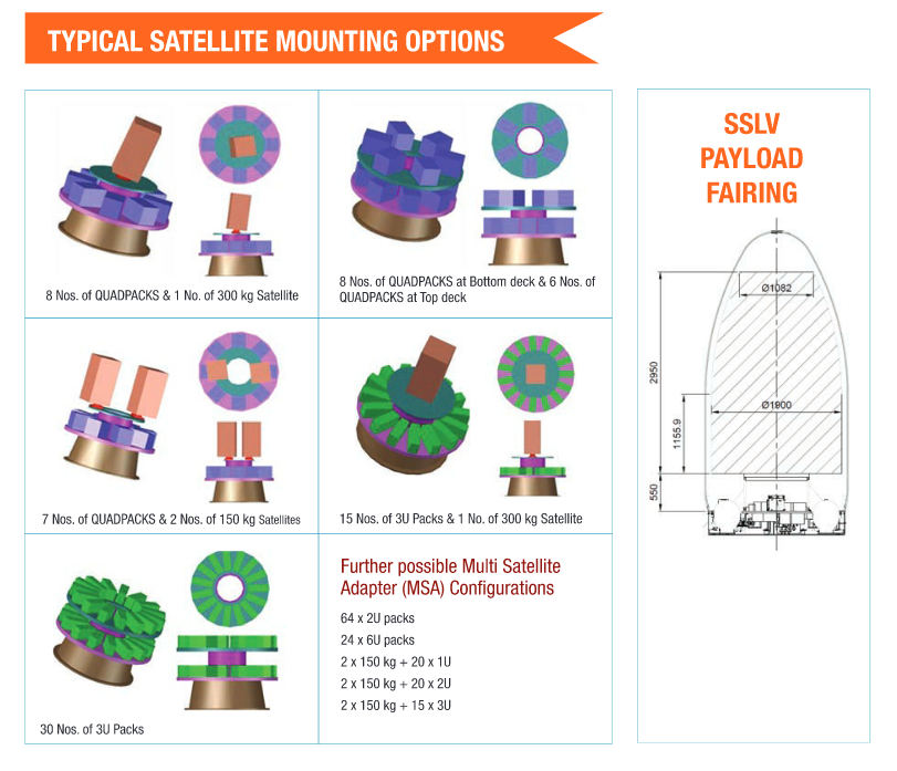 SATELLITE SEPARATION SYSTEMThe satellite separation system has the ultimate job of releasing the sensitive payload away from the terminal stage of the Launch Vehicle. ISRO has developed various satellite separation systems for the array of its launch vehicles based on mission requirements. A typical separation system has 3 main sequences 1. Actuation 2. Release 3. Separation Impulse.  ISRO Ball Lock as mentioned before functions by releasing a preloaded ball locked joint between two rings by rotating a ball retainer ring using pyro assisted thrusters. This system is characterised by good joint stiffness, lightweight construction, tuneable jettisoning velocity, debris free actuation and redundancy in initiation. The system generates low release shock. The pyro thrusters are the source of energy for release function. It is powered by ISRO standard cartridge with squib based electrical initiation. The firing of the cartridge generates pressure inside the thruster, which moves a piston and rotates the retainer ring.   For the sake of understanding we will see the example of IBL-298 used on PSLV. The configuration of the separation system is shown in images below. The system consists of three rings. The fore-end ring interfaces with the satellite. The aft end ring is attached to the launch vehicle deck. These rings are held together using a ball lock and pre-loaded radially using a retainer ring which provides the required joint stiffness. The retainer ring is locked in position using two shear screws attached to the stopper bracket. For releasing the system, the retainer ring is to be rotated overcoming the redial pre-load and friction and shearing the pins through a fixed angle. The required angle is reached when the lug of the retainer ring makes contact with the stopper mounted on the aft ring. The holes on the retainer ring align with the balls in the aft ring and jettisoning springs cause the separation of the forend ring. The configuration of the piston and the retainer lug, which is of interest in this model, is shown in Fig:4. There are two pyro thrusters mounted on a bracket attached to the aft ring keeping a small gap from the retainer ring lug. The pyro thrusters are mounted so as not to make contact with the stopper lug and retainer ring at the end of the stroke. This is to prevent the impact of the piston on the lug at the end of the stroke. There are eight sets of compressed springs providing jettisoning energy for the spacecraft. The springs react on the fore end ring, which forms a part of the spacecraft after separation. LAUNCH ON DEMANDTheir won’t be any point in developing such a launch vehicle if it uses a bulk of large no. of systems to operate. All the sub-assemblies and components made for separation systems are modular. The onboard computer has been kept simple and quickly reconfigurable to suit mission launch requirements. The avionics are said to be miniaturised for low cost using readily available industrial off the shelf. New Mission Management Computer (MMC) and Sequencing Execution Module (SEM) has been developed. The miniaturized telemetry system has been developed for SSLV has achieved 70 % mass reduction in the telemetry package. COMPETITION FROM HOME AND ABROAD.ISRO has earned 1000s of crore Rupees in revenue by launching foreign satellites and is about to make a huge dent in commercial space market by being able to launch satellites at competitive prices. But Space Industry's trend going small and cost effective has given birth to many space start-ups both in India and abroad. The SSLV was quickly made by ISRO to have a matching launch vehicle that can compete with local and foreign commercial space launch companies. Here I would list out some rockets that would give a tough competition to SSLV. 1 Kuizhou 1 China 2 Rocket Lab Electron. 3 Agnikul Agnibaan 4 Skyroot Aerospace Vikram 1 5 CAS Space ZK-1A 6 Virgin Orbit Launcher One. GALLERY      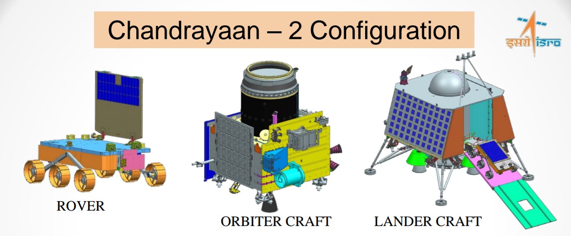 Chandrayaan 2 is India’s second moon mission. Taking a step further in lunar exploration ISRO’s Chandrayaan 2 intends to do satiate the curiosity even more by being able to send more scientific instruments for study of lunar surface. The mission is to carry Orbiter Craft Module OC and Lander Craft Module LC. The Lander Craft Module named Vikram is supposed to ferry a rover named Pragyan that would attempt to perform in-situ chemical analysis of lunar soil present at the south pole of moon. It would expand the technologies from Chandrayaan 1. This mission also intends to demonstrate newer technologies for future interplanetary missions. The OC will also carry scientific payload that would enhance the scientific objectives of Chandrayaan 1 with improved resolution. Both the OC and LC would be carried in a single launch attached to each other their composite mass is stated as 3320 kgs as of latest. The OC would have a life of 1 Earth Year and the LC and Rover would have lives of just whatever they could do until the sun sets. Both LC and Rover draw their energy from solar panels and without availability of Sun they won’t work. A usual day on moon is equivalent to 14 Earth Days so probably that is how long the rover and LC would live. MissionThe Chandrayaan 2 mission would begin with the launch of the 3850 kgs co-joined Oribiter Craft and Lander Craft via a GSLV mk3 Launch Vehicle. As GSLV mk3 with an upper stage cryogenic engine has validated itself being a reliable vehicle to launch heavier payloads. The GSLV mk3 would place Chandrayaan 2 spacecraft in Earth Parking Orbit of 170 km Apogee and 19,998 km Perigee. Later on orbit raising burns would substantially increase the Perigee until the velocity of the craft is substantial enough to hurl it into Lunar Transfer Trajectory. After which it would transferred to Lunar orbit and orbit reducing maneuvers would be done to finally stabilise the Chandu 2 into a circular polar orbit of 100km. This has been described as 'science orbit’ . After acheiveing this orbit the second phase would begin where suitable landing site and timing would be matched with previously decided ones and the LC would be separated. 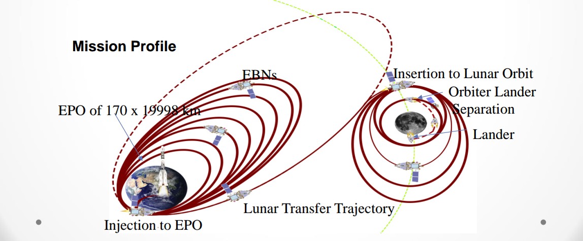 Here the LC would de-orbit and position itself in an orbit of 30km perigee , and start it's rough braking phase while decending towards the Moon. The LC would fire it's thrusters to manage the approach speeds and would come closer to 7 kms from Lunar Ground. This would be followed by an autonomous adjustment of attitude. LC would take photos and autonomously decide it's landing site and trajectory to approach it. The LC would stabilise itself vertically 100 metres above the intended landing site and with the help of it's onboard attitude control thrusters and four main thrusters slowly decend down. It's hazard avoidance system and altitude sensors would ensure prevention of any external damage to the craft. The landing legs would be deployed during this phase. The decend would continue until LC is 2 m above the surface, after which the thrusters would shut themselves off. And the landing legs would absorb the shock of landing while lander falls from 2 m above. Immidietly the rover would be deployed. The Rover is supposed to move around for 14 days and conduct chemical analysis of Moon's soil. Using it's six wheels and traction control the Rover would analyse samples at different spots across the surface, while constantly communicating with the LC, The LC with the OC and the OC communicating with Earth. The OC would perform varied experiments further enhancing those done by Chandrayaan 1. While LC would judge Moon's crust and sesmic activity along with taking photos of areas around. 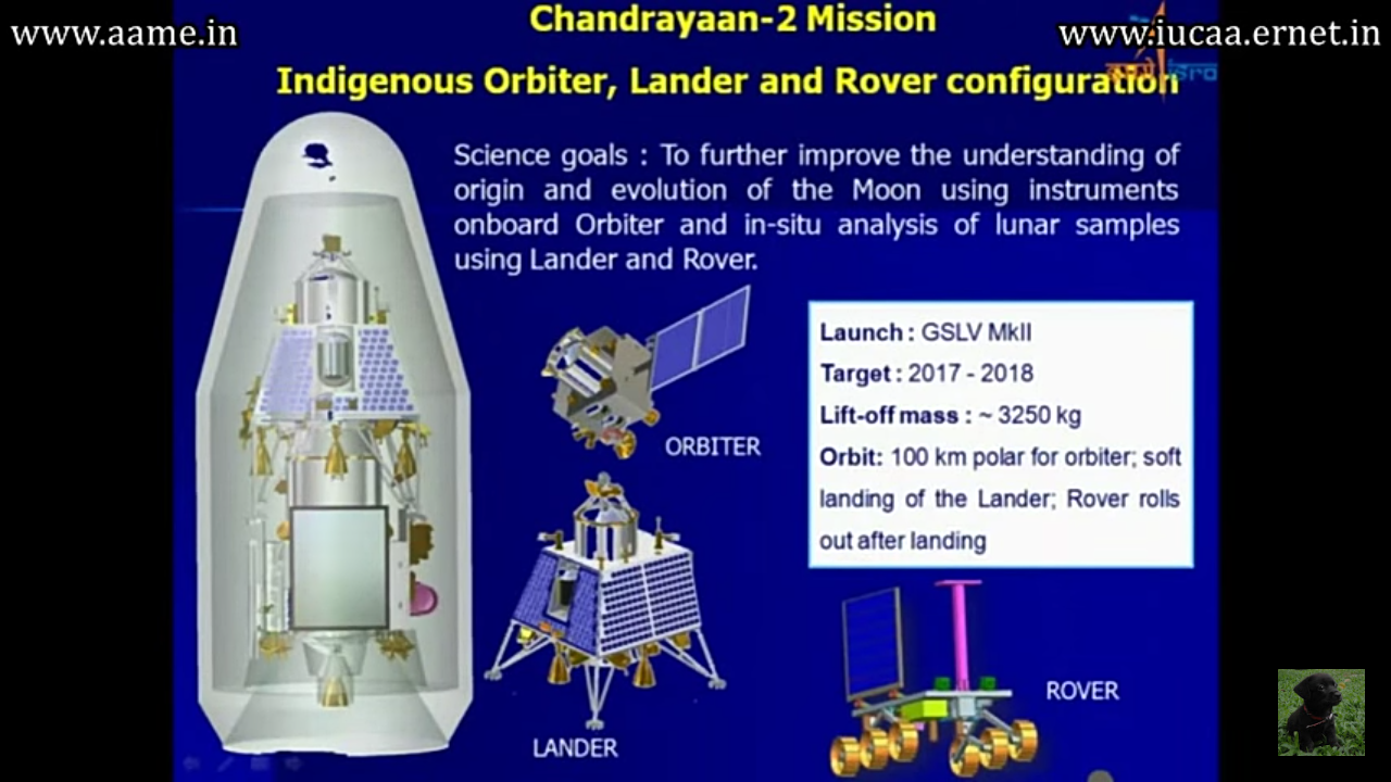 Oribiter Craft Module OCThe Orbiter has similar configuration as that of Chandrayaan 1. A box shaped craft having an internal cylinder consisting of fuel tank and main thruster at the bottom. Difference is that their was Moon Impact Probe on top of Chandrayaan 1 while the faring on the top of Chandrayaan 2 seems grossly revised in terms of strength so as to sustain the weight of LC. The top portion would attached to LC during launch and both OC and LC would separate only when they would be in lunar orbit. Their are attitude control thrusters and scientific payloads spread over the three sides of the outer surface while on the fourth side what appears to be is a deployable Solar Panel just like that of Chandrayaan 1. 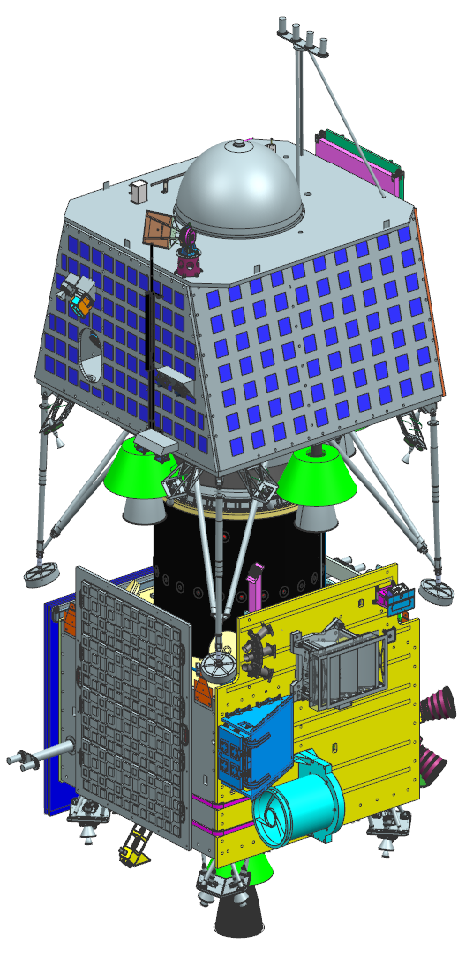 As an evolution to what Chandrayaan 1 did, the scientific payloads on Chandu 2 are evolutionary. Their are total 8 payloads on it. 1 Terrain Mapping Camera 2 :- To prepare a detailed 3D map of Moon's surface, using 2 cameras it is evolved from the TMC of Chandrayaan 1. 2 CLASS Collimated Large Array Soft X-ray Spectrometer :- It would map the abundance of major rock forming elements like Magnesium, Aluminium, Silicon, Cadmium, Titanium and Iron on moon's surface. 3 XSM X-Ray Solar Monitor :- It intends to observe the X rays emitted from the Sun’s corona which would assist the CLASS. As CLASS is a passive sensor. 4 OHRC Oribiter High Resolution Camera :- The job of this Camera is to catch high resolution images of landing site prior to landing. 5 IIRS Imaging Infrared Spectrometer :- This is the coolest thing on the module because this is going to study presence of hydroxyl (OH), Water H2O and other minerals in the polar regions of Moon. 6 SAR Synthetic Aperture Radar :- Its work is to map the geographical features like craters especially at the polar surfaces. 7 CHACE 2 Chandra's Atmospheric Composition Explorer 2 :- It is a neutral mass spectrometer that would carry out study of Moon's exosphere. 8 RAMBHA Radio Anatomy of Moon Bound Hypersensitive ionosphere and Atmosphere :- It will measure TEC total electron content. Lander Craft Module LCThe finalised design for LC consists of pyramid type design with its 3 sides having Solar Panels and the fourth one having a door and a door integrated ladder to deploy the rover, The rover would be piggybacking inside the LC. The lander has four legs to stand and during the launch while LC and OC be united those legs are supposed to be in pulled back position. Their were four main thrusters each providing ~800 N of thrust, later one more was added centrally and 8 other thrusters probably for attitude control while decent, having ~50 N thrust. To navigate the LC precisely it has LIRAP Laser Gyro based Inertial Reference unit and Accelerometer Package. It is an inertial navigation system that would precisely direct the LC to the predetermined landing site. 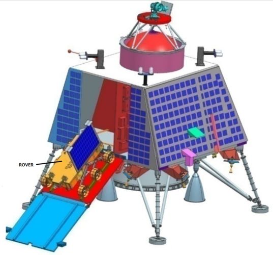 Reportedly the LC also has cameras around it these cameras can also take pictures to match with pre loaded images to determine weather LC is on the right path. The LC can intelligently self adjust it's trajectory necessary to land on the spot. These cameras are a part of Hazard Detection and Avoidance HDA system. It so happens that after the rough braking phase the Lande will stabilise itself 100 metres above moon’s surface and would slowly decend down during this phase HDA has to ensure it's movement on the right path. The HDA’s cameras would identify correct landing site using scene matching. This system also contains laser altimeters and a laser Doppler velocimiter. The HDA ensures LC would land without any external alien solid object hitting it. As soon as the LC would be 2 metres above the ground it's thrusters would shut down and landing legs streched, the legs are designed to absorb the shock. 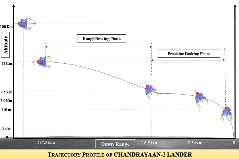 Instruments being carried by LC 1 RAMBHA (LP + DFRS) Radio Anatomy of Moon Bound Hypersensitive ionosphere and Atmosphere :- It will also measure TEC and also morphology. It will measure near surface plasma density and it's changes with respect to time. According to a recent Nature article, lunar plasma is thought to participate in the levitation of lunar dust, a problem for future human exploration. 2 ChaSTE Chandra’s Surface Thermophysical Experiment :- The job of this one would be the measurement of thermal properties of lunar regolith near polar region. 3 ILSA Instrument for Lunar Seismic Activity :- This is another first of its kind experiment as no one has the data about Lunar Crust at the poles. The ILSA would measure moon's sesmic activity around the landing site. It will be helpful in guessing the structure of Lunar Crust at south pole and mantle. RoverI very much wanted the Rover to have some name , it's un-cute to just call it rover.I was happy to kniw it has been named Pragyan. The Rover has 6 wheels that run on independent motors and are attached to the main body via a linkage. Four of the wheels will also be capable of independent steering. A total of 10 electrical motors will be used for traction and steering. The main body is shaped like a matchbox and has two instruments. Their are two cameras one in left and another in right both for navigation purpose. It doesn't have a rear vision but can go in reverse direction. The rover is about 25 kgs. Because of being designed to move on polar surface, the rover has vertical solar panels instead of usual horizontal ones we have seen on other rovers. The rover will move on moon 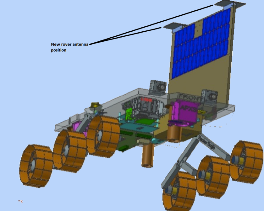 Earlier it was planned that their will be two rovers a Russian one and an Indian. The Russian rover was supposed to be based on the Phobos Grunt mission’s rover. This rover was supposed to land on Mars’ moon Phobos but that mission was a failure following which ISRO earlier decided to go on a single rover with Russian assistance and later they decide to go all alone. On August 14, 2013, in reply to a written question in the Rajya Sabha the GOI confirmed that ISRO had decided to undertake the Chandrayaan mission all by itself. IIT Kanpur was involved in development of certain components like stereophonic camera-based 3D vision, kinematic traction control, and motor dynamics of the rover's six wheels. Dr. K.S. Venkatesh, Associate Professor of Electrical engineering has developed the 3D view component. The 3D vision would create a 3D contour map of Lunar Surface after landing and would use it for navigation and mobility. Based on the obstacles and seams on surface an optimal path will be chosen to reach to a point at the expense of minimum energy. The rover also has to ensure that it's vertical solar panels would always face towards Sun for maximum power generation. The traction control would ensure that rover overcomes the roughness of moon's surface and provides optimum torque to the wheels to move at optimum speeds. 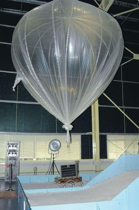 Development of the components was completed in 2012 and the rover is currently under tests. To simulate the Moon's gravity which is 1/6th of that of earth, a helium balloon has been attached to the test rover which counterbalances 5/6th of the Earth's gravitational force. This can be seen in the pictures around. The Rover's mobility is being tested a the ISRO Satellite Integration and Testing Establishment (ISITE) in Bangalore. Anorthosite rock from Sithampoondi and Kunnamalai, about 260-km from Bangalore, has been pulverized and laid out at ISITE. It has been spread over to make a mock lunar surface. The chemical and mechanical properties of the pulverized Anorthosite closely resemble those of lunar soil. S. Anbazhagan, Professor and Head of the Department of Geology, Periyar University, told The Hindu, “We had done spectral studies on the lunar soil and we discovered its equivalent at Sithampoondi." Geologists from Periyar University, Salem; the National Institute of Technology, Tiruchi; the, Indian Institute of Science, Bangalore, and the National Geophysical Research Institute, Hyderabad are collaborating with ISRO on the Chandrayaan-2 project. 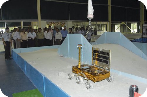 It is built to communicate with Indian Deep Space Network (IDSN) using the Lander Rover Communication System on-board the Lander, or through the Orbiter Rover Communication System on-board the Orbiter. The Rover have two scientific payloads. Intended to study moon's surface. Both are designed to do onsite elemental analysis of lunar surface and find out what's the would made of. The LIBS can find lower mass elements and APXS is for higher mass elements. 1 LIBS Laser-Induced Breakdown Spectroscope :- It will determine the chemical and mineralogical composition of Lunar Soil. It is developed by Laboratory for Electro Optic Systems, Bangalore and would do spectral analysis of lunar soil. 2 APXS Alpha Particle X-Ray Spectrometer :- It is developed by Physical Research Laboratory, Ahmedabad. It would determine elemental composition of lunar soil. Geo-Political ImpactIt may pain in the heart of the Chinese that they lost the opportunity to send Asia's fist Mars mission as ISRO did it, But they still own the records of many firsts in the field of Space Exploration. Indians are highly egoistic about their achievements and grossly pessimistic about those things where they got initial failures. We can see Indian media and people bragging about the success of ISRO. They brag that Pakistani Space Agency SUPARCO is older but still less successful than ISRO also take a snub against China which is very wrong activity. It is true that these chievements accompany National Pride with themselves and we all must be proud but taking a jibe on someone who failed trying makes us a loser in long term. During the cold war their was a rivalry amongst USA and USSR to achieve firsts in Space Exploration. 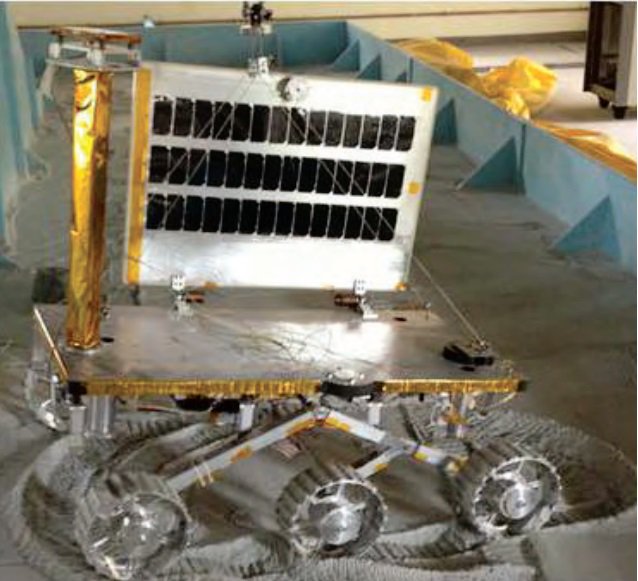 Such a rivalry kills the very basic thing about study of science, that is curiosity. It is curiosity, scientific temper that stimulates people to take bold steps. It doesn't matter who launched the spacecraft first and who second, everyone wins when more and more spacecrafts are launched for exploration purposes. But it isn't necessary that everyone in the world would carry the same feeling of brotherhood that we may seek. India had always been unlike China open to international collaboration and participation of all space agencies in building and managing scientific payloads on it's exploration missions. All the space exploring nations have shared scientific data they recieved. So it's not like we are trying to defeat each other by winning so called Space Race, we all won over our curiosity and the thrust is more now. ISRO has taken correct and careful steps towards lunar exploration , this step of Chandrayaan 2 would validate many technologies intended for further planetary touch downs. The next Chandrayaan mission after this shall be a sample return type where samples collected by a rover would be ferried back to Earth. Indian prime minister Narendra Modi and his Japanese counterpart Shinzo Abe signed an agreement to collaborate on a future joint lunar sample return mission. Wish Successful Launch to Chandrayaan 2 !Images and Info Sources :-
http://www.planetary.org/blogs/emily-lakdawalla/2017/1129-indias-chandrayaan-2-mission.html https://sites.google.com/site/indianspaceprojects/moon-exploration/chandrayaan---2 Introduction Chandrayaan-1 was India’s first unmanned lunar probe. It was launched by the Indian Space Research Organization (ISRO) in 22nd October 2008, and operated until August 2009. Chandrayaan-1 is aimed at chemical, mineralogical and photo-geologic mapping of the moon in visible, near infrared, low energy and high energy X-rays with high spatial resolution. Specifically, the objectives will be to carry out high-resolution three-dimensional mapping of topographic features along with the simultaneous mapping of distribution of minerals such as Si, Al, Mg, Ca, Ilmenites (FeTiO3, which may retain 3He) and elemental chemical species including radioactive nuclides. This mapping could unravel the mysteries about the origin and evolution of the planetary system in general and moon-earth system in particular. 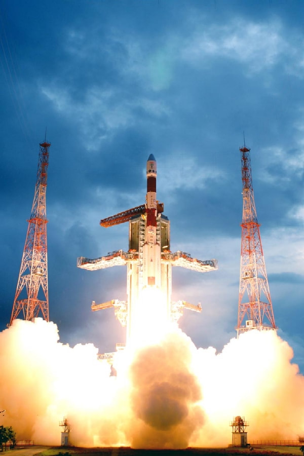 About Moon Looming at about 384,400 km from the Earth, the Moon is the brightest object in the night sky and only second in brightness to that of the Sun. It has a diameter of 3,476 km and a mass of 7.35x10²² kg with a mean density of only 3.35 g/cc as compared to 5.52 g/cc of that of Earth. It has no atmosphere and degassing from the surface produces only trace gases. The gravitational force on the Moon is only 1/6th of that of Earth, and is not able to retain its atmosphere. The Moon does not have a substantial core of molten iron like Earth and hence has no magnetic field. The Moon undergoes extremes in temperature. It is scorching heat at 110º C during the day and freezing cold at .180º C during night. The Moon.s surface is generally dry, dusty and rocky. The rocky crust is about 60 km thick on the near side that faces the Earth and about 107 km on the far side. Moon.s terrain is divided into two sharply contrasting areas. The rugged and very ancient mountainous .Highlands regions and smooth younger lowland, Maria regions. While Earth.s mountain ranges are formed by movements and coming closer of crust sections pushing against each other (known as plate tectonics), the lunar highlands did not result from an active uplifting process due to crustal dynamics. But its surface has been periodically bombarded with different sizes of meteorites and asteroids. During the initial period of lunar evolution, such giant meteor impacts resulted in the creation of flatlands or lunar basins. The regions not affected by these giant impacts are the lunar highlands. Ancient observers thought that the round and dark areas on the face of the Moon are seas, which they called Maria (Latin word for seas). Maria are not seas at all but relatively flat areas produced by massive flow of lava from earlier period of lunar volcanism. Maria comprises 16 percent of the Moon.s surface and has huge impact basins. They are concentrated in the near side of the Moon. Associated with the Lunar Maria are gravity anomalies called mascons (mass concentrations). A spacecraft would accelerate as it nears the Maria region and decelerate as it moves away due to such gravitational anomalies. The Moon is covered with a gently rolling layer of powdery soil and rock fragments called the regolith, which is made of debris created by the meteor impacts forming the craters. Such craters are the remains of collisions between an asteroid, comet or meteorite and the Moon. The size, mass, speed and angle of the falling object determine the size, shape and complexity of resulting craters. Surface of the Moon is scarred with millions of impact craters and the record has been retained on Moon,s surface. One striking difference between the lunar surface material and that of Earth concerns the most common kinds of rocks. On the Earth the most common rocks are sedimentary because of atmospheric and water erosion of the surface. On the Moon there is no atmosphere and little or no water, and the most common kind of rock is igneous (.fire-formed-rocks.). According to studies, the lunar surface material has the following geological characteristics:
Analysis of lunar rock samples indicate that
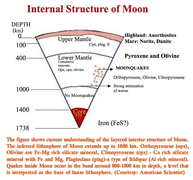 The abundance of radioactive elements in rock samples can be used to determine the age of the rocks in a process called radioactive dating. Using such techniques on lunar samples brought back by the Apollo missions, it has been found that the oldest material from the surface of the Moon is almost as old as we believe the Solar system to be that is 5 billion years. Thus the material brought back from the Moon by Apollo missions provides a window on the very early history of our Solar system that would be difficult to find on the Earth, which is geologically active and has consequently obliterated its early geological features. Seismic S waves apparently do not traverse the region below the zone of Moonquakes, suggesting that this material has very low shear strength, possibly containing some liquid. 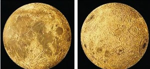 Origin of Moon The origin of the Moon is still not clearly understood and there have been speculations about its origin how it was formed and how it acquired its present orbit around the Earth. Studies using the chemical, mineralogical, isotopic and chronological data led to postulation of five major theories on the origin of the Moon: The Fission Theory: At some time in the distant past, the Moon had separated from the Earth Perhaps the Earth was not as round then as it is today and that imbalance caused it to split in two. The Capture Theory: The Moon was formed somewhere in the solar system and was later captured by the gravitational field of the Earth. The Co-accretion Theory: The Earth and Moon may have been formed at the same time from solar nebula by co-accretion. The Colliding Planetesimal Theory: Moon condensed from the debris of the interaction of Earth-orbiting and Sun-orbiting planetesimals (very large chunks of rocks like asteroids) early in the history of the solar system. The Giant Impact Theory: A planetesimal of Mars size had impact with the Earth, early in its history, ejecting large volume of matter from the evolving Earth, which aggregated and formed the Moon. 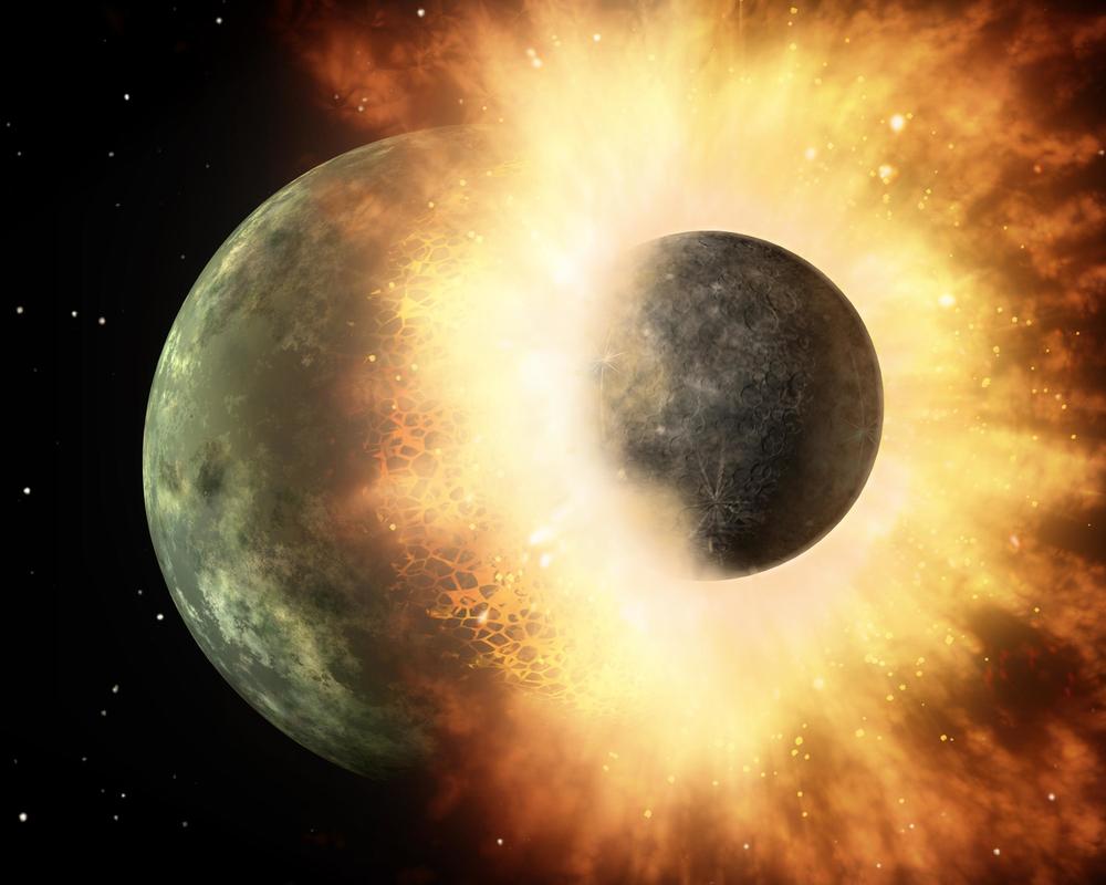 Why Moon Apart from the scientific interest, the Moon could have economic benefits to mankind. This includes exploitation of the resource potential of the Moon including habitation of the Moon to reap the benefits on a continuous basis. The Moon has abundant resources of oxygen, hydrogen and other solar wind gases trapped in its regolith. Understanding the availability of such resources from the perspective of mineralogy, lithology and regional geology is a prerequisite for efficient human presence on the Moon. Early studies of the lunar regolith showed that there is a relative abundance of Helium-3 (3He) isotope on the Moon compared to that of Earth. 3He can be used as a fusion element and is thus considered as one of the important fuels for power generation in the future. Since 3He has high diffusivity, it normally gets lost from lunar grains. However, the mineral Ilmenite (FeTiO3) is abundant on the Moon and has high retentivity for 3He. The distribution of 3He associated with Fe and Ti can be determined by geochemical mapping since it would have the same distribution as (Fe + Ti). Over the four billion-year history of the Moon, several hundred million tonnes of 3He have impacted the surface of the Moon from the solar wind. The analyses of Apollo and Luna samples showed that over 1 million tonnes of 3He still remain embedded in the surface of the Moon. Even a small fraction of this could provide the world.s electricity for centuries to come. A large number of studies are being carried out to determine the technical feasibility of having a human outpost on the Moon. The twenty-first century will mark a significant milestone in the history of human development: the colonization of the Moon! The Moon being the nearest neighbor of Earth and with 1/6 th of the Earth’s gravity offers a unique outpost for planetary exploration. The conditions may be adapted to generate lunar self-sustaining bases for such endeavors. Moon’s far side would provide an excellent site for establishing an astronomical observatory because of the absence of atmosphere and the absence of Earth’s reflected radiation on the far side of Moon. Propulsion in a broad sense is the act of changing the motion of a body. Propulsion mechanisms provide a force that moves bodies that are initially at rest, changes a velocity, or overcomes retarding forces when a body is propelled through a medium. Jet propulsion is a means of locomotion whereby a reaction force is imparted to a device by the momentum of ejected matter.  Rocket propulsion is a class of jet propulsion that produces thrust by ejecting stored matter, called the propellant. Duct propulsion is a class of jet propulsion and includes turbojets and ramjets; these engines are also commonly called air-breathing engines. Duct propulsion devices utilize mostly the surrounding medium as the "working fluid", together with some stored fuel. The energy source most useful to rocket propulsion is chemical combustion. Energy can also be supplied by solar radiation and, in the past, also by nuclear reaction. Accordingly, the various propulsion devices can be divided into
 Radiation energy can originate from sources other than the sun, and theoretically can cover the transmission of energy by microwave and laser beams, electromagnetic waves, and electrons, protons, and other particle beams from a transmitter to a flying receiver. Nuclear energy is associated with the transformations of atomic particles within the nucleus of atoms and can be of several types, namely, fission, fusion, and decay of radioactive species. Other energy sources, both internal (in the vehicle) and external, can be considered. The energy form found in the output of a rocket is largely the kinetic energy of the ejected matter; thus the rocket converts the input from the energy source into this form. The ejected mass can be in a solid, liquid, or gaseous state. Often a combination of two or more of these is ejected. At very high temperatures it can also be a plasma, which is an electrically activated gas. DUCT JET PROPULSION This class, also called air-breathing engines, comprises devices which have a duct to confine the flow of air. They use oxygen from the air to burn fuel stored in the flight vehicle. The class includes turbojets, turbofans, ramjets, and pulsejets. ROCKET PROPULSION Rocket propulsion systems can be classified according to the type of energy source
The basic function
The type of vehicle
Another way is to Classify by the method of producing thrust. A thermodynamic Expansion of a gas is used in the majority of practical rocket propulsion concepts. The internal energy of the gas is converted into the kinetic energy of the exhaust flow and the thrust is produced by the gas pressure on the surfaces exposed to the gas, This same thermo-dynamic theory and the same generic equipment (nozzle) is used for jet propulsion, rocket propulsion, nuclear propulsion, laser propulsion, solar-thermal propulsion, and some types of electrical propulsion. Totally different methods of producing thrust are used in other types of electric propulsion or by using a pendulum in a gravity gradient. Chemical Rocket Propulsion The energy from a high-pressure combustion reaction of propellant chemicals, usually a fuel and an oxidizing chemical, permits the heating of reaction product gases to very high temperatures (2500 to 4100°C or 4500 to 7400°F). These gases subsequently are expanded in a nozzle and accelerated to high velocities (1800 to 4300 m/sec or 5900 to 14,100 ft/sec). Since these gas temperatures are about twice the melting point of steel, it is necessary to cool or insulate all the surfaces that are exposed to the hot gases. According to the physical state of the propellant, there are several different classes of chemical rocket propulsion devices. Liquid propellant rocket engines use liquid propellants that are fed under pressure from tanks into a thrust chamber. 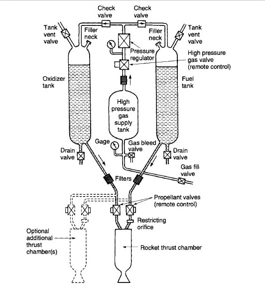 A typical pressure-fed liquid propellant Rocket engine system is schematically shown in Fig The liquid bipropellant consists of a liquid oxidizer (e.g., liquid oxygen) and a liquid fuel (e.g., kerosene). A monopropellant is a single liquid that contains both oxidizing and fuel species; it decomposes into hot gas when properly catalyzed. 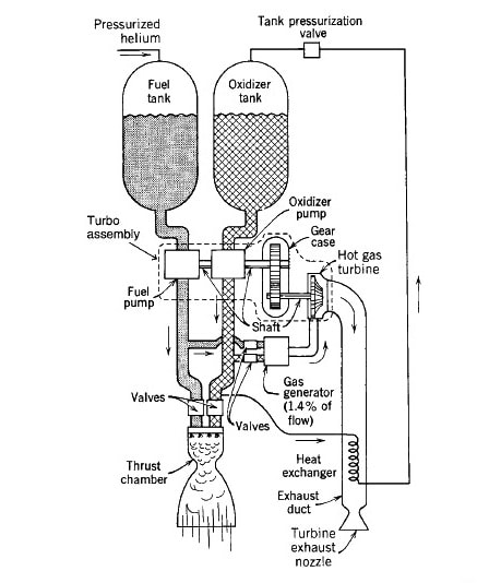 A large turbopump-fed liquid propellant rocket engine is shown in this Fig Gas pressure feed systems are used mostly on low thrust, low total energy propulsion systems, such as those used for attitude control of flying vehicles, often with more than one thrust chamber per engine. Pump-fed liquid rocket systems are used typically in applications with larger amounts of propellants and higher thrusts, such as in space launch vehicles. In the thrust chamber the propellants react to form hot gases, which in turn are accelerated and ejected at a high velocity through a supersonic nozzle, thereby imparting momentum to the vehicle. A nozzle has a converging section, a constriction or throat, and a conical or bell-shaped diverging section Gas pressure feed systems are used mostly on low thrust, low total energy propulsion systems, such as those used for attitude control of flying vehicles, often with more than one thrust chamber per engine. Pump-fed liquid rocket systems are used typically in applications with larger amounts of propellants and higher thrusts, such as in space launch vehicles. Some liquid rocket engines permit repetitive operation and can be started and shut off at will. If the thrust chamber is provided with adequate cooling capacity, it is possible to run liquid rockets for periods exceeding 1 hour, dependent only on the propellant supply. A liquid rocket propulsion system requires several precision valves and a complex feed mechanism which includes propellant pumps, turbines, or a propellant-pressurizing device, and a relatively intricate combustion or thrust chamber. In solid propellant rocket motors the propellant to be burned is contained within the combustion chamber or case. The solid propellant charge is called the grain and it contains all the chemical elements for complete burning. Once ignited, it usually burns smoothly at a predetermined rate on all the exposed internal surfaces of the grain. Initial burning takes place at the internal surfaces of the cylinder perforation and the four slots. The internal cavity grows as propellant is burned and consumed. The resulting hot gas flows through the supersonic nozzle to impart thrust. Once ignited, the motor combustion proceeds in an orderly manner until essentially all the propellant has been consumed. There are no feed systems or valves 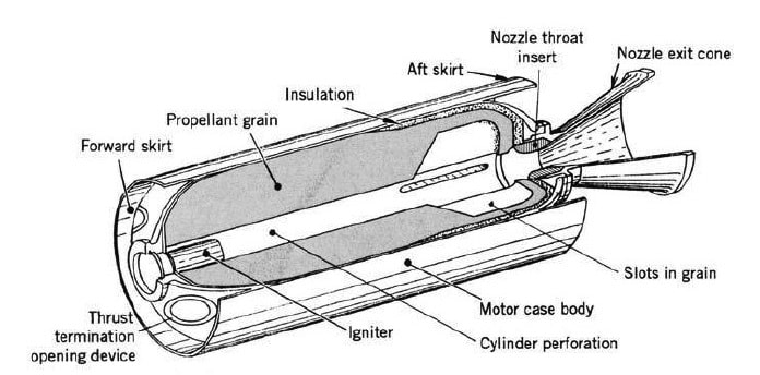 Gaseous propellant rocket engines use a stored high-pressure gas, such as air, nitrogen, or helium, as their working fluid or propellant. The stored gas requires relatively heavy tanks. These cold gas engines have been used on many early space vehicles as attitude control systems and some are still used today. Heating the gas by electrical energy or by combustion of certain monopropellants improves the performance and this has often been called warm gas propellant rocket propulsion. Hybrid propellant rocket propulsion systems use both a liquid and a solid propellant. For example, if a liquid oxidizing agent is injected into a combustion chamber filled with solid carbonaceous fuel grain, the chemical reaction produces hot combustion gases. 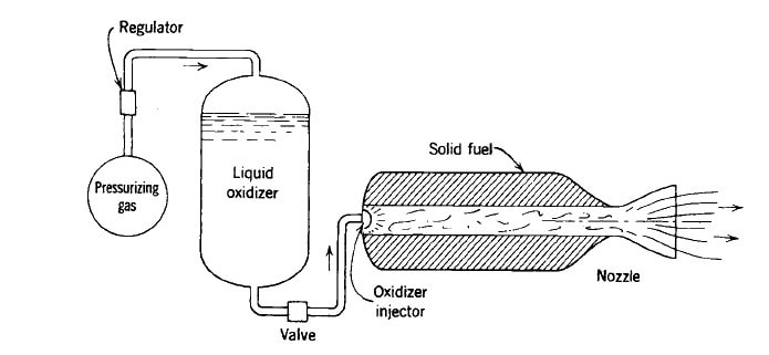 There are also chemical rocket propulsion combination systems that have both solid and liquid propellants. One example is a pressurized liquid propellant system that uses a solid propellant to generate hot gases for tank pressurization; flexible diaphragms are necessary to separate the hot gas and the reactive liquid propellant in the tank.
|
AuthorANOOP MADHAVAN Archives
August 2022
Categories |
 RSS Feed
