|
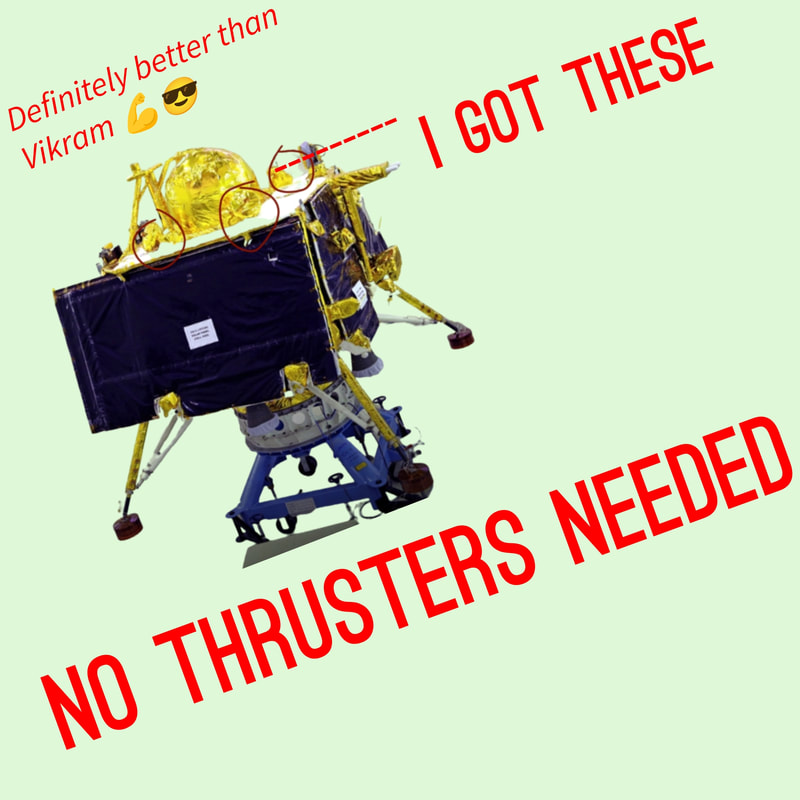
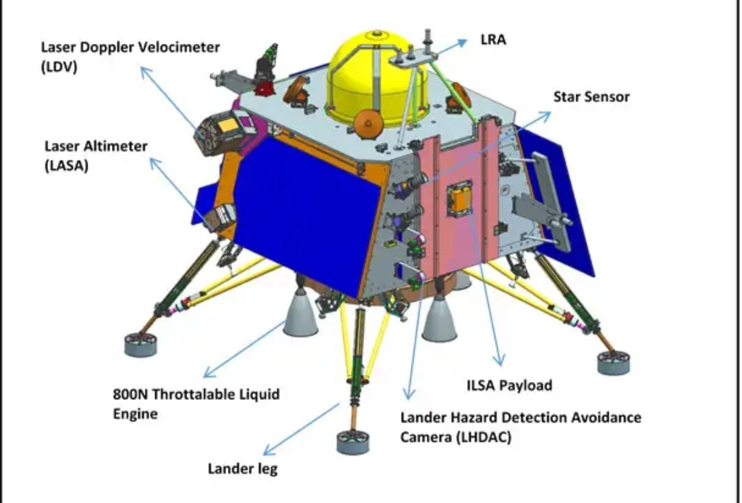
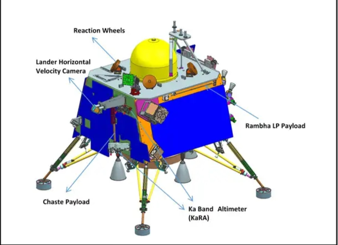
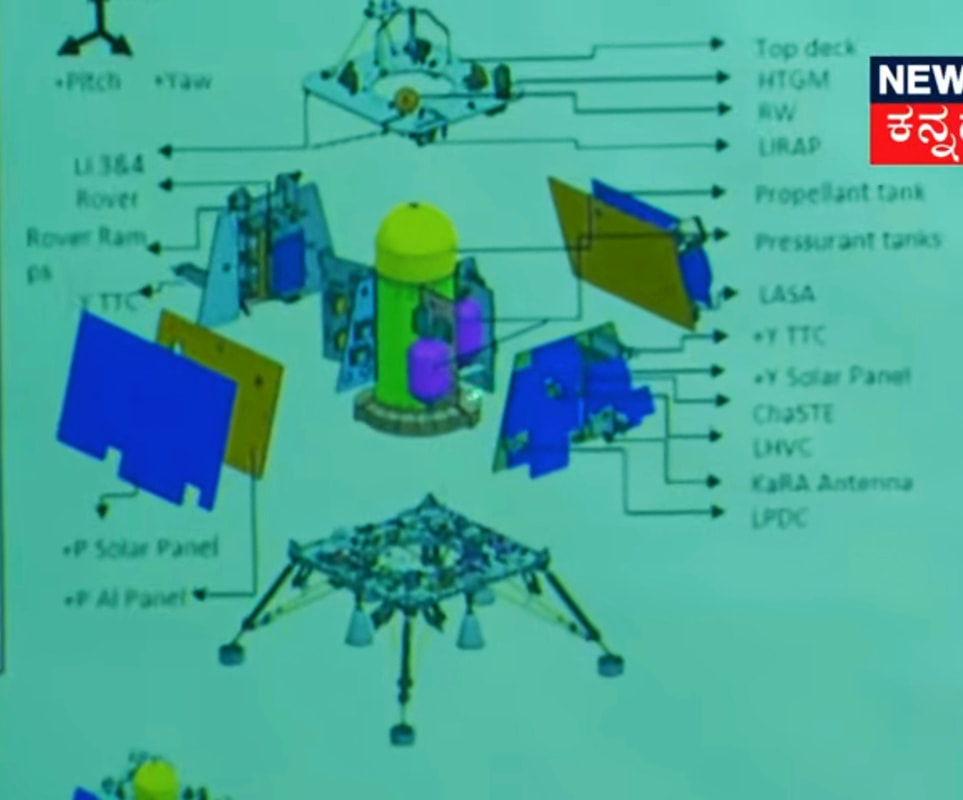
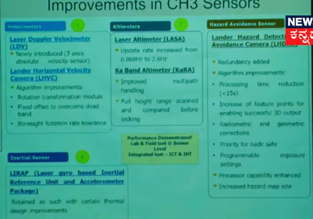
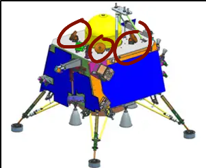
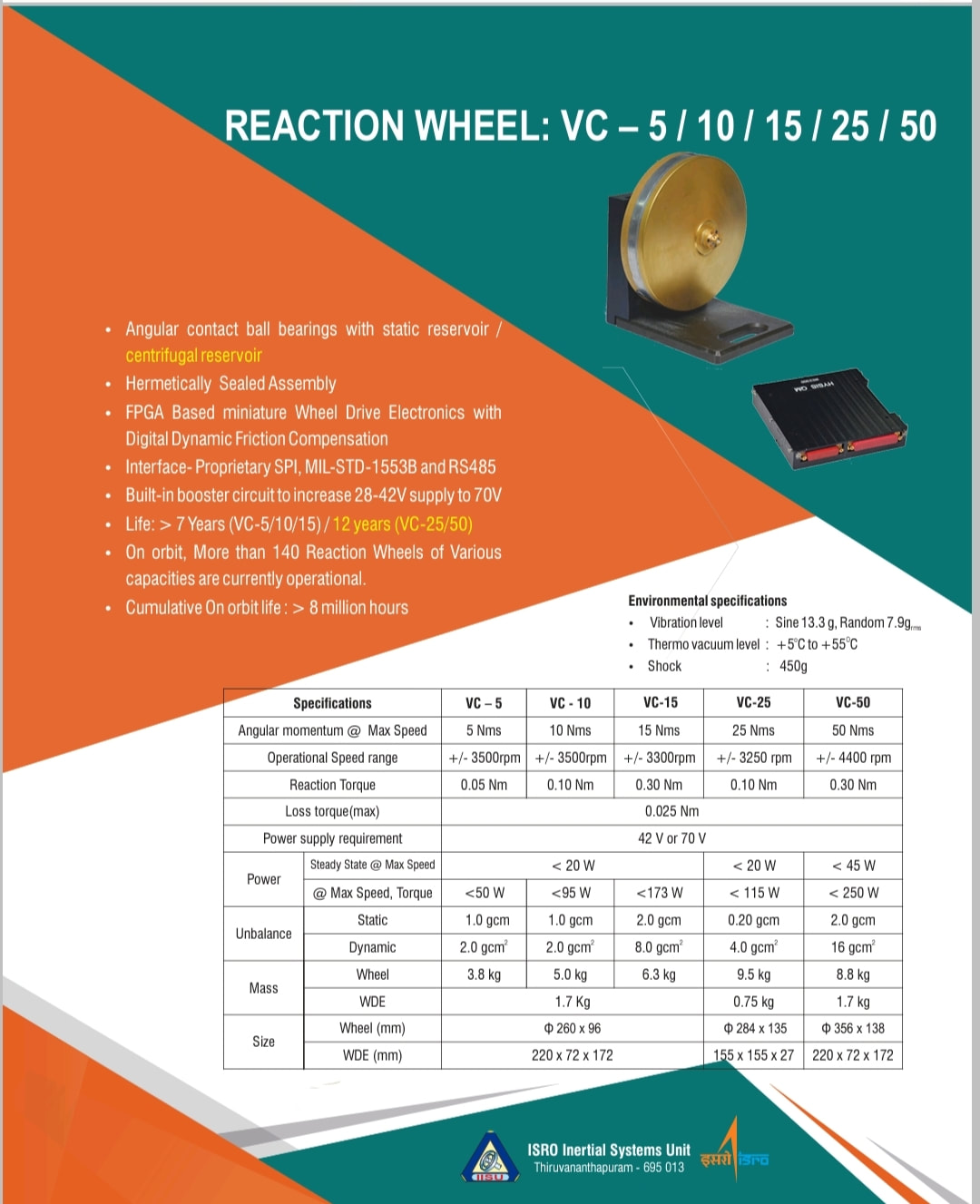
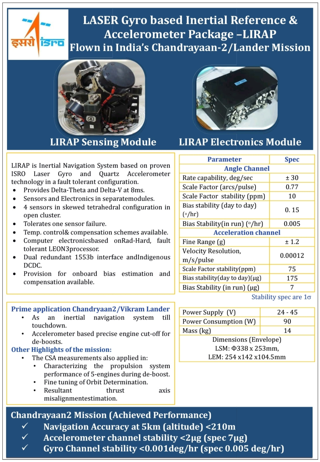
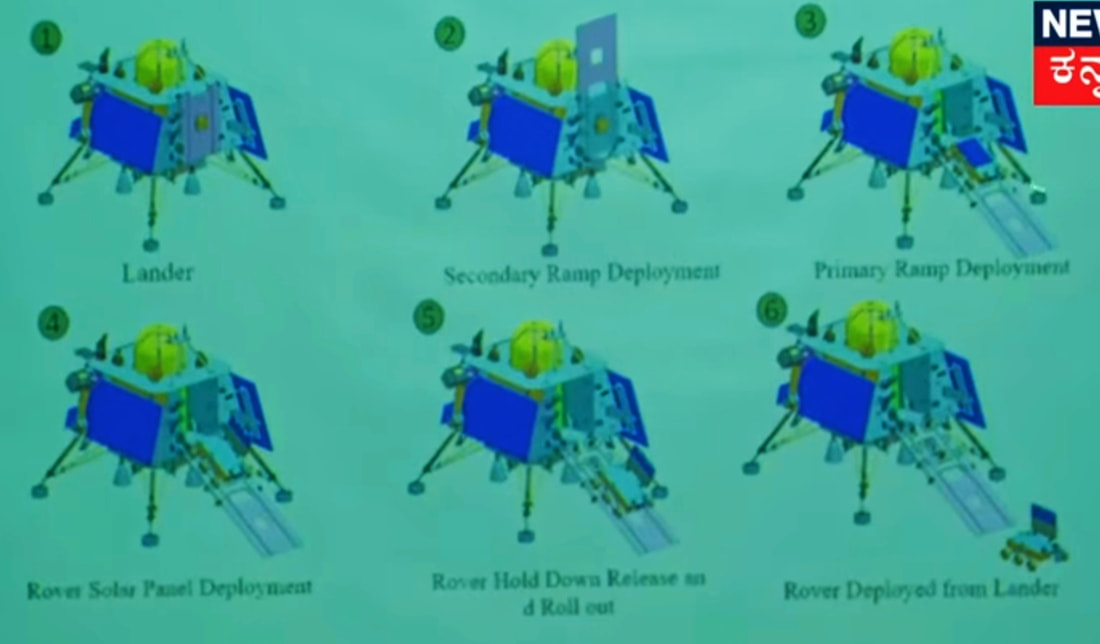
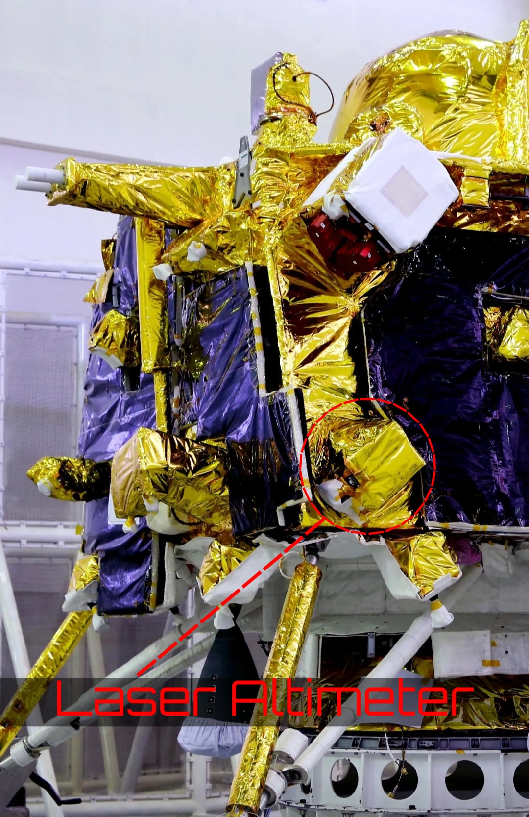
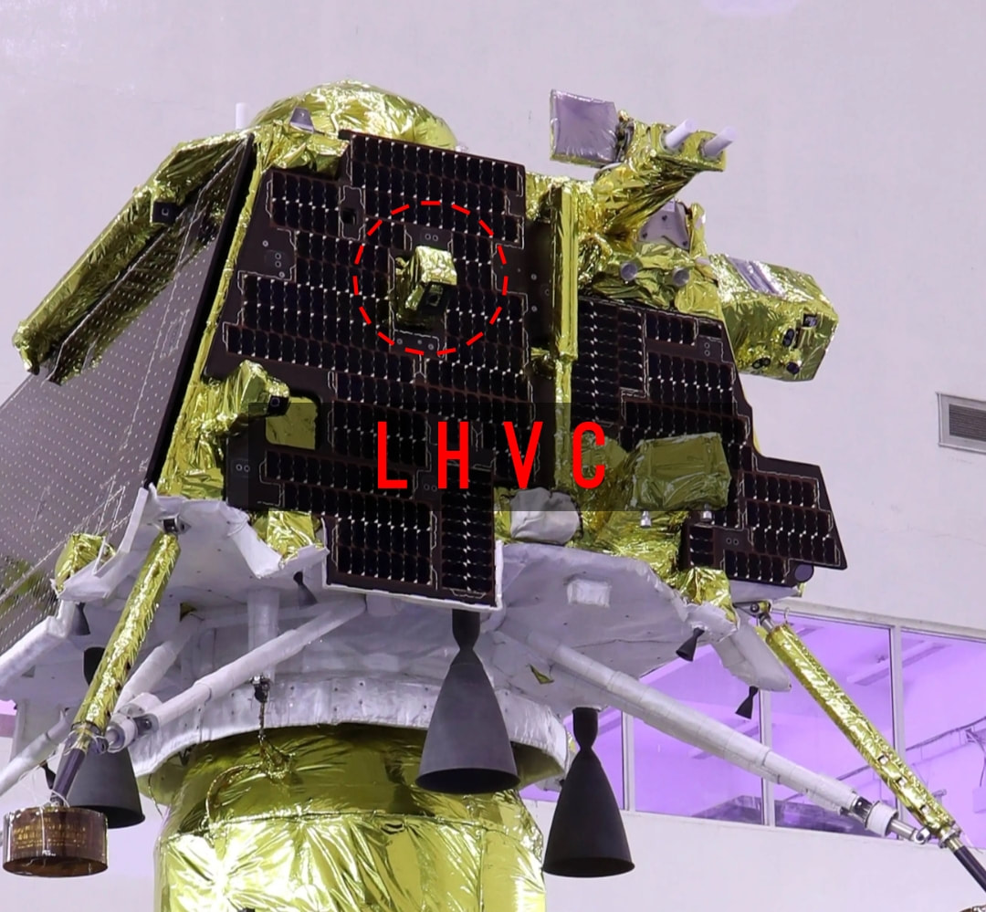
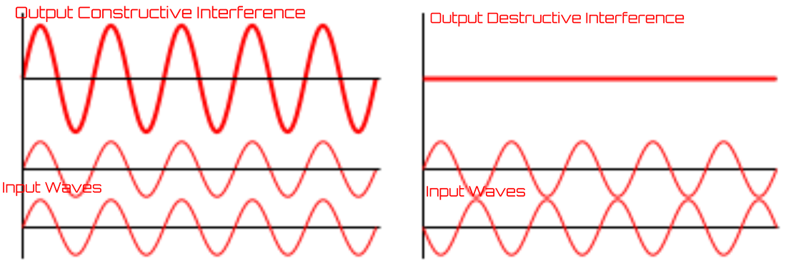
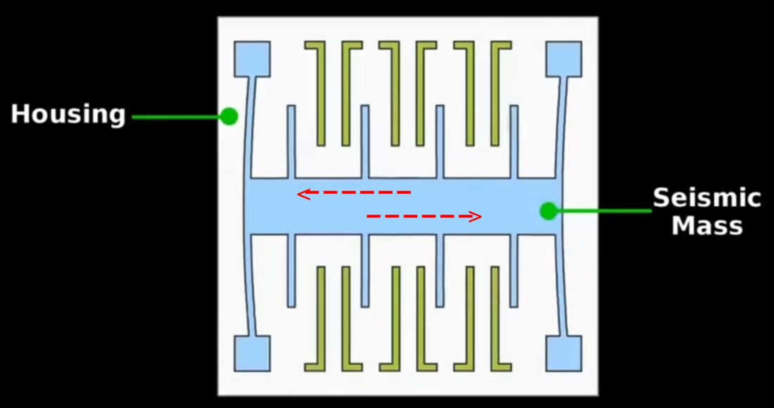
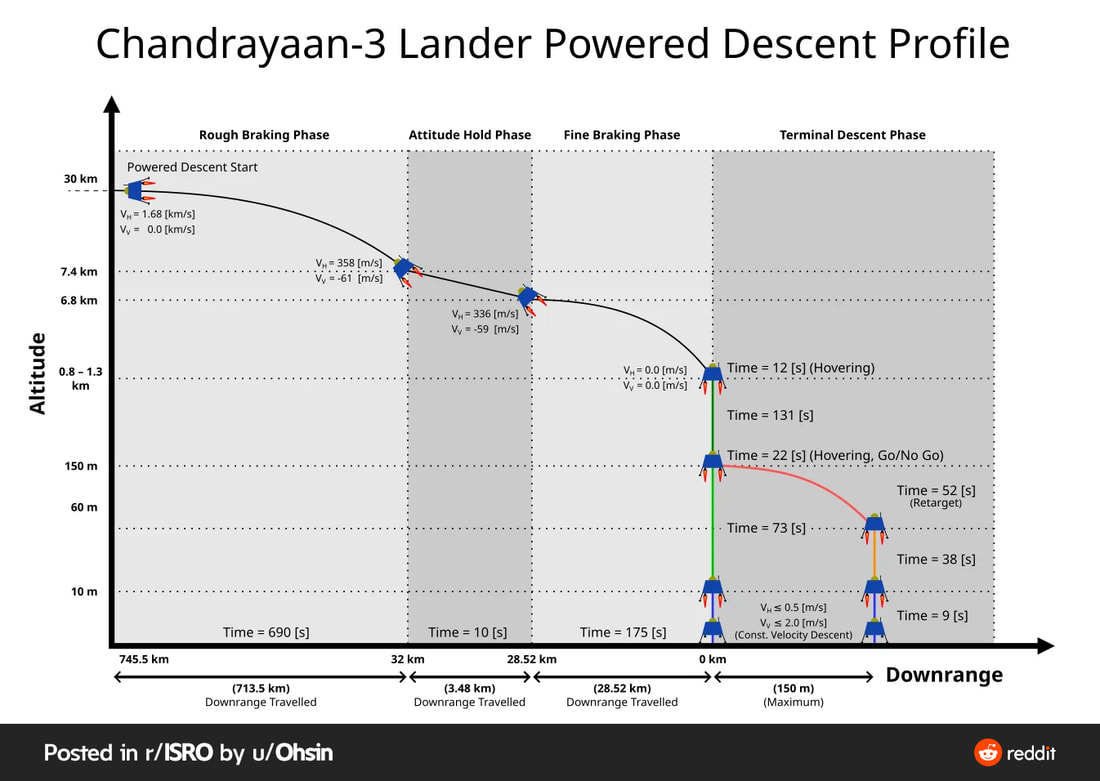
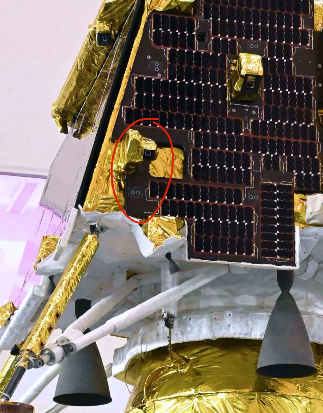
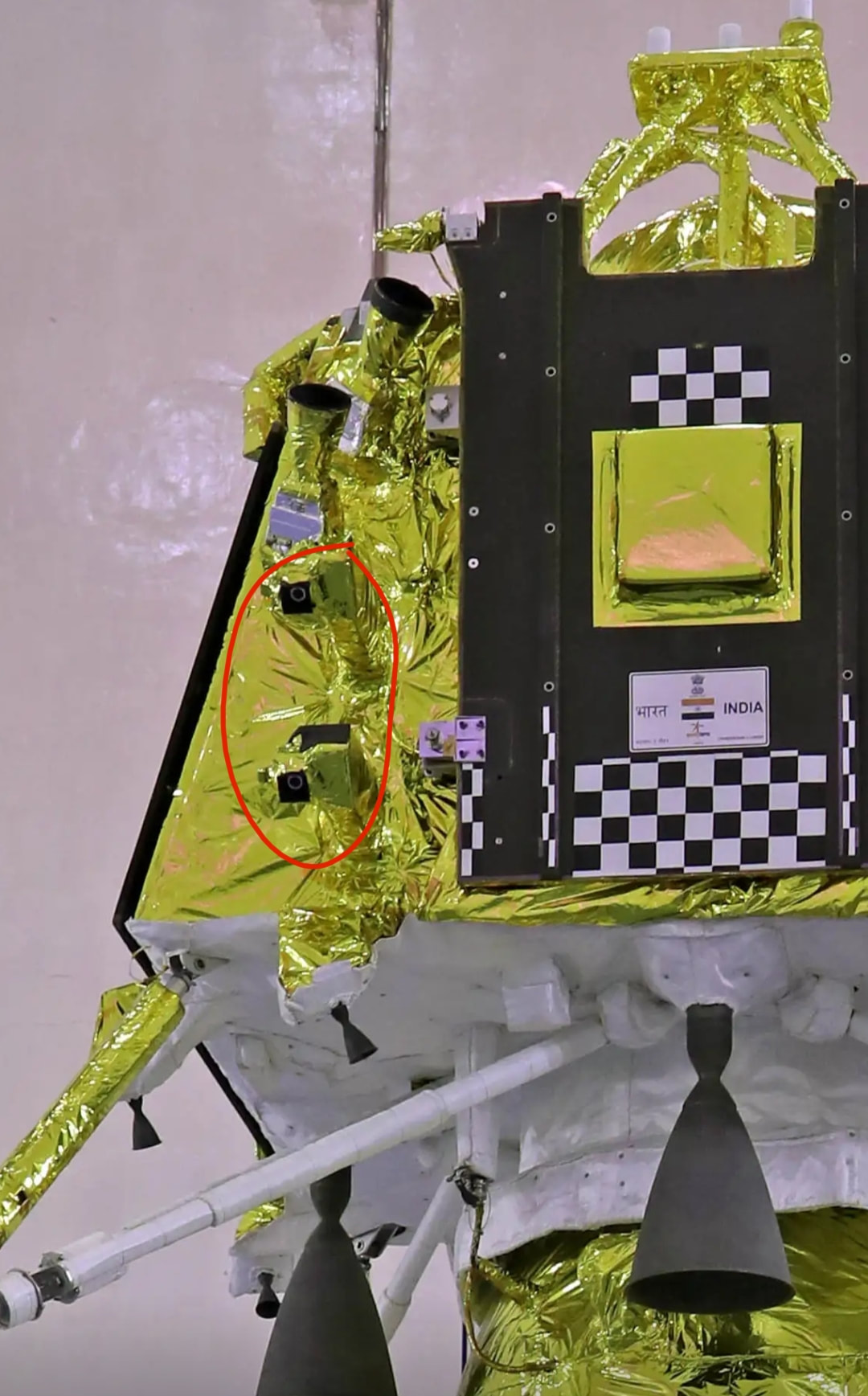
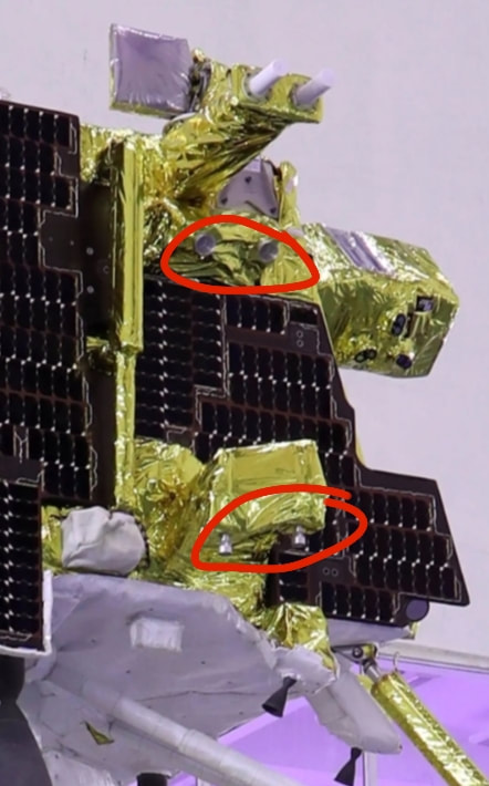
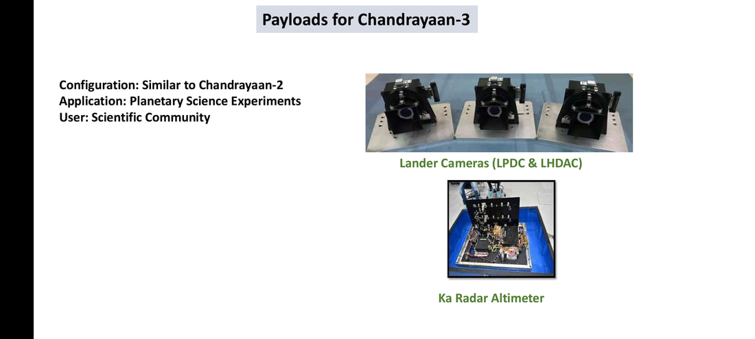
We all are seeing pretty detailed explanation of the science payload of Chandrayaan 3 and the scientific activities that will be performed on Moon. We have till now seen the detailed explanation of the gravity assist orbit raising maneuvers performed by the Chandrayaan 3 orbiter to get the lander to the moon. We have been closely following the path as CH-3 is approaching the moon. But how exactly the lander works? How exactly it finds it's location with respect to it's surroundings? How does the lander controls it's orientation? How is it going to find i's way to the landing spot? We know we control our vehicles through our steering wheels and see the surrounding through our eyes while we drive. We know that we have a control strick to maneuver an aircraft in the air, but how does a spacecraft controls it's motion? This article attempts to explain in details the sensors on CH-3 lander that are dedicated for spacecraft navigation and control and the functioning behind them. The sensors on CH-3 lander are shown in the images below. 1. REACTION WHEELSReaction Wheels as the name suggests are wheels that generate a reaction torque and help change the orientation of spacecraft. Reaction wheels are used to control the orientation of a satellite without the use of thrusters, which reduces the mass of needed fuel for reaction thrusters. They work by equipping the spacecraft with an electric motor attached to a flywheel, which, when its rotation speed is changed, causes the spacecraft to begin to counter-rotate proportionately through conservation of angular momentum. Reaction wheels can rotate a spacecraft only around its center of mass; they are not capable of moving the spacecraft from one place to another. Let me try my absolute best to make you understand this. We all have learned Newton's 3rd law of motion, to every action their is an equal and opposite reaction. The thing that we call Force in linear motion, the same thing is called Torque in circular motion. And Newton's 3rd law when applied in context of circular motion would be like to every rotation their is an equal and opposite rotation. When we move a reaction wheel in zero gravity environment it forces the satellite body to rotate in an opposite direction. Since their are 3 axes of rotation we need motors to rotate reaction wheels that control rotation in all 3 axes. Sometimes two adjacent wheels that are 90deg are rotated simultaneously so that the resultant rotation of a spacecraft happens around an axis that is 45deg to those wheel's axis. This is shown in the video below. I am putting a lot of videos at the end of this pargraph to make you understand how it works. It is hard to understand since we hardly notice it in our day to day lives. But reaction wheels are nowadays a standard part of every spacecraft and it is the least discussed technological Marvel in space technology in my opinion. Chandrayaan 3's lander has 4 reaction wheels at the location shown below. The Vikram lander of Chandrayaan 2 also had them at the exact same spot. The reaction wheels have a max 10 Nms angular momentum and can generate 0.1 Nm Torque for comparison we need 1.7 to 2.2 Nm Torque to open a water bottle. This can give you an idea about the level of precision that goes into making the reaction wheels. Reaction wheels have famously been used in Hubble space telescopes to increase it's pointing accuracy. The lander can thus make very minute, precise corrections in it's orientation while approaching the moon. The Reaction wheels of ISRO satellites are made by ISRO inertial systems unit and their is a wide variety of reaction wheels ranging to different angular momentum and torque are available.\u0000 2. LIRAPRover Deployment Sequence.After checking health of all the science payloads and the rover one by one the payload will be activated. Solar Array will activate all vital functions. At around 2015 IST the rover ramp will be deployed. At 2045 IST Rover is switched on and at 2125 IST Rover deploys it's solar panels. At 2140 IST Rover rollout begins. At 2150 IST Rover touches regolith. At 2205 IST Rover takes pictures of the lander. Wishing successful landings to Chandrayaan 3 Source - Chandrayaan-3: 'Vikram' Landing Attempt Updates and Discussion. https://www.reddit.com/r/ISRO/comments/15waz81/chandrayaan3_vikram_landing_attempt_updates_and/ https://www.isro.gov.in/chandrayaan3_gallery.html https://www.isro.gov.in/Chandrayaan3_New.html 5. Laser Altimeter (LASA)A typical laser altimeter determines the range between the instrument and laser footprint by measuring round trip time of laser pulse. The return pulse reflected from surface is gathered by the receiver of laser altimeter, the pulsewidth and amplitude of which are changeable with the variability of the ground relief. Few years ago DRDO LASTEC helped develop a Laser Altimeter. I suspect it was for Chandrayaan. https://www.drdo.gov.in/diode-pumped-ndyag-laser-space-based-altimeter 6. Laser Doppler Velocimeter (LDV)Need to understand Doppler effect before understanding this device. Do you remember hearing the sound of a siren made by a passing train. Kindly recall that sound in your memory or quickly see a YouTube video. The sound of siren is more when train is approaching you while the sound of siren is less when it is going away from you. You will know if you have observed correctly. This phenomenon is called Doppler effect. We also use some knowledge of constructive and destructive interference and fringe pattern to do something called "optical interferometery" just look at the gooddamn wordplay here. Interferometery means measuring distances using interference and nothing else. 7. Lander Horizontal Velocity Camera (LHVC)This camera constantly takes pictures of the landing sites and compares pictures of the lunar surface features with previous ones. An algorithm is developed to estimate the relative horizontal velocity using the complete camera perspective projection model The images can be used to estimate the horizontal velocity of a lander during the descent phase. This can be used to update the velocities computed by Inertial Navigation System which is based on Accelerometer/Gyro outputs. Since inertial systems measurements of instantaneous velocities are inaccurate due to drift bias and laser Doppler velocity sensor takes too much power the LHVC has been developed. https://www.researchgate.net/publication/338649784_Image_based_Horizontal_Velocity_Estimation_Algorithm_for_the_Descent_phase_of_an_Interplanetary_Lander 8. Micro Star sensor.A preloaded Map of Night sky and position of stars at a particular time is used and the star sensor spots the stars and compares it's position with the preloaded map. This helps identify the position of the sensor. The star sensor is a complex machine that performs various functions in it's processing unit to estimate the position and orientation of a spacecraft with respect to a reference star. This sensor first estimates the centres of stars and then indentifies the stars followed by estimation of attitude (orientation with respected to reference). The data provided by star sensor helps CH-3 lander compare measurements taken by other sensors with some reference to validate the correctness of it's path. I have provided links for further reading. Detailed reading would make one understand the complexity involved in this scientific feat. I am giving some links below for further reading. Further Reading https://www.researchgate.net/publication/315667278_Design_and_Finite_Element_Analysis_of_Mini_Star_Tracker www.reddit.com/r/ISRO/comments/dd482a/details_on_isro_built_multihead_star_sensor_under/&ved=2ahUKEwiF7vCnzO6AAxXc_rsIHUXmASg4ChAWegQIBBAB&usg=AOvVaw0Qavgo5MaRL6kn6yp3NRbD 9. Inclinometer & Touchdown sensorsThe LEOS ( Laboratory for electro optic sensors) had developed an MEMS based inclinometer long back ago. The inclinometer has technological commonality with ILSA sensor on CH-3 lander. The MEMS (Micro Electro Mechanical System) based sensor has a proof mass attached to a flexible material, on the other side the flexible material is rigidly attached to a fixed surface. The mass dielectric material attached to it placed in between two charged plates. When the Mass moves the dielectric moves and changes capacitance in between the two charged plates. This change in capacitance corresponds to the physical movement of Proof Mass. ( You need to learn what's a capacitor before understanding this) The seismic sensor on Lander works similarly but measures moonquaqes instead of inclination. I suspect their is an inclinometer on the rover as well. I tried my level best to find info on the functioning of the Touchdown sensor but could hardly find any. The Touchdown sensor is designed to detect contact between regolith and landing leg pads. Their are more than one ways to detect and initiate a shut down signal closing off all thrusters. It's really hard to make a guess. Landing Sequence2 Hours prior to landing a poll will be conducted based on health of lander and landing site conditions the poll will result in a "Go" or "No-Go" decision. If the decision ends in No-Go then landing attempt will be shifted to 27th August 2023. ISRO cheif even said that if conditions not met then they may postpone the landing attempt to September. Unlike previous attempt this time we have high resolution images of the potential landing sites taken by Chandrayaan 2. At 1745 IST / 1215 UTC powered decent will begin and all 4 engines will be fired for 11 Min 30 Sec. The rough breaking phase will end here and a 10 second long altitude holding phase will be initiated, lander will begin tilting at ~50° lander expected to decent upto 6.8 km altitude during these 10 seconds. At 1756 IST Fine braking phase begins and two engines out of 4 engines are shut off. The phase will last 2 min 55 sec. Lander drops to the altitude 0.8 - 1.3 km. At 1759 IST Lander hovers for 12 seconds to survey the landing site and instruments callibrate during this time. At 1800 IST (approx) Lander begins verticle decent that will last 2 min 11 seconds. Lander drops down to an altitude of 150m. At 1803 IST Lander will hover for 22 seconds to detect potential hazards like boulders and big sized rocks and make a Go-NoGo decision to land or not. If a Go decision is taken then lander decends to 10m altitude at 1805 IST (approx) and initiates landing at a decent rate of 1m/sec. Which means at 1815 (approx) the lander will touch down the regolith. If a No-Go decision is taken lander will select an alternate landing spot 150m away from main spot and decent to 60m altitude above altenate landing spot at 1803 IST and decent down to 10m altitude at 1804 IST. It will begin landing at a decent rate of 1m/sex and touch down at 1814 (approx). The Touchdown sensors will confirm contact with regolith and shut down all thrusters. Even if communication with CH-3 orbiter fails the lander has an X Band antenna to directly communicate with earth confirming it's status. 4. Lander Position Detection Camera (LPDC) LHDAC (Lander Hazard Detection & Avoidance Camera)These features were added later on CH-3 lander and are going to enhance overall survivability. The functions are simple to understand from the names themselves. I am putting photos of potential locations of these cameras. These cameras are sidelined amongst other sensors but they will get a major role incase CH-3 lander decides to select an alternate landing spot. This feature is a major difference between CH-3 lander and Vikram. It will be exciting to see pictures of around the moon from these cameras. 3. Ka-Band Altimeter (KaRA)This is a simple radio frequency based sensor used for measuring altitude constantly. The radar works by sending a focussed wave towards a target an then recieving the wave after some time. Based on the time taken between sent wave and received wave the distance between object and target is calculated using the old school speed = distance / time. Since radio frequency waves are fast it helps calculate the distance between CH-3 lander and lunar surface very fast. This sensor may be for redundancy purpose because their is a laser based sensor exactly for altitude measuring purpose. The Ka-band radar altimeter (KaRA) system attached to the Vikram lander will activate 7.5 km above the lunar surface and send the necessary inputs to the ISRO headquarters. The processors of the hazard detector camera and KaRA were designed by Ahmedabad's ISRO centre. Chandrayaan 3's lander has 4 reaction wheels at the location shown below. The Vikram lander of Chandrayaan 2 also had them at the exact same spot. The reaction wheels have a max 10 Nms angular momentum and can generate 0.1 Nm Torque for comparison we need 1.7 to 2.2 Nm Torque to open a water bottle. This can give you an idea about the level of precision that goes into making the reaction wheels. Reaction wheels have famously been used in Hubble space telescopes to increase it's pointing accuracy. The lander can thus make very minute, precise corrections in it's orientation while approaching the moon. The Reaction wheels of ISRO satellites are made by ISRO inertial systems unit and their is a wide variety of reaction wheels ranging to different angular momentum and torque are available.\u0000 I am putting a lot of videos at the end of this paragraph to make you understand how it works. It is hard to understand since we hardly notice it in our day to day lives. But reaction wheels are nowadays a standard part of every spacecraft and it is the least discussed technological Marvel in space technology in my opinion. Sometimes two adjacent wheels that are 90deg are rotated simultaneously so that the resultant rotation of a spacecraft happens around an axis that is 45deg to those wheel's axis. This is shown in the video below. 1. Reaction WheelsLeave a Reply. |
AuthorANOOP MADHAVAN Archives
August 2022
Categories |
 RSS Feed
